Note : Les descriptions sont présentées dans la langue officielle dans laquelle elles ont été soumises.
CA 02797821 2014-06-20
TITLE: APPARATUS AND METHOD FOR FRACTURING A WELL
INVENTORS:
Sean Patrick Campbell and William Jani
TECHNICAL FIELD:
The present disclosure is related to the field of apparatuses and
methods for fracturing a well in a hydrocarbon bearing formation, in
particular,
down-hole valve subassemblies that can be opened to fracture production
zones in a well.
BACKGROUND:
It is known to use valve subassemblies placed in well casing that can
be opened once the well casing has been cemented into place. These valve
subassemblies or "subs" can use a ball valve seat mechanism that can
receive a ball placed into the casing. Once the ball is seated in the valve
seat, flow through the valve sub is cut off. The pressure of fracturing fluid
injected into the casing will cause the closed valve seat mechanism to slide a
piston forward in the valve sub thereby opening ports in the wall of the valve
sub to allow the pressure of the fracturing fluid penetrate into a production
zone of a hydrocarbon bearing formation. The ball valve seat mechanism can
be comprised of varying sized openings. Typically, a number of the valve
subs are placed in series in the casing at predetermined intervals in spacing
CA 02797821 2012-10-29
WO 2011/134069
PCT/CA2011/000495
2
along the well into the formation. The largest diameter valve seat is placed
nearest the top of the well with progressively smaller diameter valve seats
with each successive valve sub place in the casing string. In this manner, the
further valve sub, the one having the smallest diameter opening can be closed
by placing the matching sized ball into the casing, which can pass through all
of the preceding valve subs, each having larger diameters than the valve sub
being closed, until the ball reaches its matching valve sub.
One shortcoming of these known ball valve seat mechanisms is that
they cannot be cemented into place with a casing string, as there is no way to
clean or wipe the cement out of the valve seat mechanisms. These
mechanisms have to be run on a liner with open hole packers in a well bore,
which is more costly to carry out.
Another shortcoming is that the volume of fluid, and the rate of fluid
flow, is constricted by the progressively decreasing diameter of the ball
valve
seat mechanism disposed in each of the valve subs, which becomes
increasingly restricted with each successive valve sub in the well. While the
number of these valve subs can be as high as 23 stages, put in place with a
packer system, the flow-rate that can be obtained through these valve subs is
not high, for example, a flow rate of 15 cubic metres per minute cannot be
obtained through these valve subs.
It is, therefore, desirable to provide a fracturing valve sub that
overcomes the shortcomings of the prior art.
CA 02797821 2012-10-29
WO 2011/134069
PCT/CA2011/000495
3
SUMMARY:
An apparatus and method for fracturing a well is provided. In one
embodiment, the apparatus comprises a valve subassembly that is further
comprised of a tubular valve body having upper and lower ends, the valve
body comprising at least one port extending through a sidewall thereof nearer
the upper end. In some embodiments, the cross-sectional area of the port or
ports can be equal to the cross-sectional area of valve body inside diameter.
In so doing, the apparatus can allow produced fluids to enter into the
apparatus at or near the same rate of flow that the fluids can pass through
the
apparatus. The apparatus can further comprise a tubular piston slidably
disposed within the valve body. The piston can move from a closed position
where the at least port is closed to an open position where the at least one
port is open. The apparatus can further comprise one or more shear pins
disposed between the piston and the valve body to hold the piston in the
closed position. When sufficient force is placed on the piston, the shear pins
can shear away to allow the piston to move from the closed position to the
open position.
The apparatus can also comprise a tubular sleeve disposed within the
piston. The sleeve or the piston can comprise grooves disposed on an
interior side wall thereof extending from an upper end to a lower end thereof.
The grooves can be configured to receive a dart configured to engage the
sleeve or the piston so as to close off the passageway extending through the
apparatus and to apply downward force against the sleeve that, in turn, places
the downward force on the piston to move from the closed to open position.
CA 02797821 2012-10-29
WO 2011/134069
PCT/CA2011/000495
4
In operation, an apparatus can be placed in a casing string near a
production zone in a well. In
other embodiments, a plurality of the
apparatuses can be placed at predetermined locations along the casing string
to enable the fracturing of the well at a plurality of production zones
disposed
therein. The grooves disposed on the sleeve or the piston can be configured
to allow keys disposed on a dart to either pass through the sleeve or piston,
or
to engage the sleeve or piston so at to open that particular apparatus. When
a plurality of apparatuses are used in casing string, the apparatus nearest
the
top of the well can comprise sleeve grooves that are wider than the sleeve
grooves of the next apparatus placed further down the casing string.
Accordingly, each successive apparatus can comprise sleeve grooves
narrower than the preceding apparatus. Therefore, the apparatus at the end
of the casing string will have the narrowest sleeve grooves of all the
apparatuses disposed in the casing string. Thus, when the dart for the last
apparatus, that is, the dart with the narrowest keys, is inserted into the
casing
string and moved along by the pressurized fracturing fluid injected into the
well following the dart, the keys of that dart can pass through the sleeve
grooves of each apparatus that precedes the last apparatus. When this dart
reaches the last apparatus, the dart keys can engage the sleeve grooves and
hold the dart in place. The pressurized fracturing fluid contacts dart cups
disposed on an upper end of the dart to apply downward force on the cups to
engage the sleeve to thereby move the piston to the open position. Once the
piston is in the open position, the pressurized fracturing fluid can pass
through
the valve port(s), breaking the casing cement to provide a path to the
CA 02797821 2012-10-29
WO 2011/134069
PCT/CA2011/000495
formation and then fracture the formation so as to allow produced fluids enter
into the casing string through valve ports. As the dart keys can provide
means to simply hold the dart in place against its corresponding sleeve until
the pressurized fracturing fluid can contact the dart cups and, hence, the
5 sleeve and piston, finer graduations in dart key width and corresponding
sleeve groove width can be implemented. In so doing, the inventor believes
that the number of apparatuses used in a single casing string can be in the
range of 16 to 30 or more. In addition to this, the sleeve of each apparatus
can have the same inside diameter from the first apparatus to the last
apparatus in the casing string to thereby enable the same volume and flow
rate of produced fluids through each apparatus as opposed to prior art
devices.
In some embodiments, each apparatus can comprise a corresponding
dart with keys configured to only engage the sleeve or piston grooves of that
apparatus. The grooves of the apparatus can be configured into particular
profiles that will only match a corresponding profile on a matching dart. As
such, a dart can pass through an apparatus where the profile do not match.
Matching profiles will allow the dart to lock into the grooves and the
pressurized fracturing fluid contacts dart cup disposed on an upper end of the
dart to apply downward force on the cup to engage the piston to thereby move
the piston to the open position.
Broadly stated, in some embodiments, an apparatus is provided for
fracturing a well, comprising: a tubular valve body comprising upper and lower
ends defining communication therebetween, the valve body further comprising
CA 02797821 2012-10-29
WO 2011/134069
PCT/CA2011/000495
6
at least one port extending through a sidewall thereof nearer the upper end; a
tubular piston slidably disposed in the valve body and configured to provide
communication therethrough, the piston closing the at least one port in a
closed position, the piston opening the at least one port in an open position;
means for moving the piston from the closed position to the open position
when a downward force is placed on the piston; and a tubular end cap
disposed on the lower end of the valve body, the end cap configured to stop
the piston when the piston moves from the closed position to the open
position.
Broadly stated, in some embodiments, the apparatus further comprises
a dart comprising a longitudinal shaft comprising upper and lower ends, the
lower end comprising a key, the key configured to engage the grooves
disposed in the moving means, the upper end comprising at least one dart
cup configured to seal off communication through the piston when the key has
engaged the grooves.
In some embodiments, a method is provided for fracturing a well in a
formation, the method comprising the steps of: providing a valve sub
apparatus and placing the apparatus in a casing string disposed in the well,
the apparatus located near a production zone in the formation; placing a dart
into the casing string; and injecting pressurized fracturing fluid into the
casing
string wherein the fracturing fluid moves the dart through the casing string
into
the apparatus until the keys of the dart engage the sleeve to place a
downward force on the sleeve to move the piston from the closed position to
CA 02797821 2012-10-29
WO 2011/134069
PCT/CA2011/000495
7
the open position wherein the fracturing fluid can pass through the at least
one port of the apparatus to fracture the formation.
Broadly stated, in some embodiments, a system of darts and keys for
use downhole in a well is provided, the system comprising: at least one
apparatus, the apparatus comprising: a tubular valve body comprising upper
and lower ends defining communication therebetween, the valve body further
comprising at least one port extending through a sidewall thereof nearer the
upper end; a tubular piston slidably disposed in the valve body and configured
to provide communication therethrough, the piston closing the at least one
port in a closed position, the piston opening the at least one port in an open
position; means for moving the piston from the closed position to the open
position when a downward force is placed on the piston; a tubular end cap
disposed on the lower end of the valve body, the end cap configured to stop
the piston when the piston moves from the closed position to the open
position; and at least one dart comprising a longitudinal shaft comprising
upper and lower ends, the lower end comprising a key, the key configured to
engage the grooves disposed in the moving means, the upper end comprising
at least one dart cup configured to seal off communication through the piston
when the key has engaged the grooves, where the dart key is configured to
specifically engage the moving means of a particular apparatus and the key
can be targeted to the particular apparatus.
CA 02797821 2012-10-29
WO 2011/134069
PCT/CA2011/000495
8
BRIEF DESCRIPTION OF THE DRAWINGS:
Figure 1 is a side cross-sectional elevation view depicting a fracturing
valve subassembly.
Figure 2 is a side cross-sectional elevation view depicting the body of
the valve subassembly of Figure 1.
Figure 3 is a side cross-sectional elevation view depicting the end cap
of the valve subassembly of Figure 1.
Figure 4 is a side cross-sectional elevation view depicting the piston of
the valve subassembly of Figure 1.
Figure 5 is a top plan view depicting the sleeve of the valve
subassembly of Figure 1.
Figure 6 is a side cross-sectional elevation view along section lines A-A
depicting the sleeve of Figure 5.
Figure 7 is a side elevation view depicting the dart of the valve
subassembly of Figure 1.
Figure 8 is a front elevation view depicting an embodiment of the dart
of Figure 7.
Figure 9 is a front elevation view depicting an alternate embodiment of
the key of the dart of Figure 7.
Figure 10 is a side cross-sectional view depicting a well in a formation
with a plurality of the valve subassemblies of Figure 1.
Figure 11 is a perspective cut-away view depicting a further
embodiment of a fracturing valve subassembly in a closed position.
CA 02797821 2012-10-29
WO 2011/134069
PCT/CA2011/000495
9
Figure 12A is a side cross-sectional elevation view depicting the
fracturing valve subassembly of Figure 11 in a closed position.
Figure 126 is a side cross-sectional elevation view depicting the
fracturing valve subassembly of Figure 11 in an open position.
Figure 13 is a perspective view depicting an embodiment of the dart of
the valve subassembly of Figure 11.
Figure 14 is a close-up side cross-sectional elevation view depicting
the fracturing valve subassembly of Figure 12A and a dart.
Figures 15A ¨ 15D are close-up side cross-sectional elevation view
depicting possible embodiments of key profiles for the fracturing valve
subassembly of Figure 12A and the corresponding key profiles of the darts.
DETAILED DESCRIPTION OF EMBODIMENTS
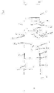
Referring to Figures Ito 6, an embodiment of fracturing valve sub 10 is
shown. The major components of valve sub 10 comprise valve body 12, end
cap 16 disposed on a lower end of body 12, tubular piston 20 slidably
disposed within body 12 and tubular sleeve disposed within piston 20. When
assembled, piston 20 is held position within body 12 by shear pins 25
disposed in holes 24. Each valve sub 10 can further comprise a dart 22 that
corresponds to a particular valve sub 10.
Referring to Figure 2, one embodiment of valve body 12 is shown in
more detail. In the illustrated embodiment, body 12 can comprise ports 14
extending through the sidewall of body 12 nearer the upper end thereof.
Ports 14 provide a means for pressurized fracturing fluid to pass through and
CA 02797821 2012-10-29
WO 2011/134069
PCT/CA2011/000495
fracture a production zone of a formation. In a representative embodiment,
the total cross-sectional area of ports 14 can be approximately equal to the
cross-sectional area of the inside diameter of valve sub 10 itself such that
there is little or no flow restriction of fluids passing through ports 14 in
or out of
5 valve sub 10. In one embodiment, body 12 can comprises holes 24 disposed
below ports 14 for receiving shear pin 25, as shown in Figure 1. In another
embodiment, body 12 can comprise ratchet threads 26 disposed on the
interior surface thereof. In a further embodiment, body 12 can comprise
threads 27 disposed at a lower thereof for releasably coupling to end cap 16,
10 as shown in Figure 1.
Referring to Figure 3, one embodiment of end cap 16 is shown in more
detail. End cap 16 can comprise threads 17 disposed on an upper end
therefor for releasably coupling with threads 27 disposed on body 12. In
another embodiment, end cap 16 can comprise cogs 28 disposed on its upper
end for engaging with piston 20, as described in more detail below.
Referring to Figure 4, one embodiment of piston 20 is shown in more
detail. As shown, piston 20 can comprise a tubular member further
comprising one or more seal grooves 34 disposed along the length of piston
20, the grooves extending circumferentially around piston 20. Seal grooves
34 can be configured to receive o-rings or any other suitable sealing member
as well known to those skilled in the art. In the illustrated embodiment, two
seal grooves 34 are disposed at an upper end of piston 20 whereas another
pair of seal grooves 34 can be disposed nearer the middle of piston and a
single seal groove 34 disposed near the lower end of piston 20. In one
CA 02797821 2012-10-29
WO 2011/134069
PCT/CA2011/000495
11
embodiment, piston 20 can comprise shoulder 21 disposed on the interior
surface thereof for retaining sleeve 18 in position, as shown in Figure 1.
Piston 20 can further comprise holes 36 disposed on the exterior surface
thereof to receive shear pins 25, as shown in Figure 1. In another
embodiment, piston 20 can comprise ratchet ring 38 disposed around the
lower end thereof, which is configured to engage ratchet threads 26 disposed
on the interior surface of body 12. In a further embodiment, piston 20 can
comprise cogs 40 disposed on the lower end thereof, cogs 40 being
configured to engage cogs 28 on end cap 16.
Referring to Figures 5 and 6, an embodiment of sleeve 18 is shown. In
this embodiment, sleeve 18 can be comprised of a tubular member
comprising peaks 30 disposed on one end thereof, and keyways 32 extending
therethrough on an interior surface thereof. As shown in Figure 1, sleeve 18
is disposed within piston 20 sitting on shoulder 21.
Referring to Figures 7 and 8, an embodiment of dart 22 is shown. Dart
22 can comprise of shaft 23, one or more dart cups 44 disposed on the upper
end thereof and one or more keys 42 disposed nearer the lower end thereof,
keys extending substantially perpendicular to shaft 23. Dart cups 44 can be
circular in configuration, when viewed from the top, or of any other
configuration such that darts cups 44 can substantially contact the interior
surface of piston 20 when pressurized fracturing fluid is injected into the
well.
In this embodiment, keys 42 can comprise an oval cross-sectional shape. In
another embodiment, keys 42 can comprise a keystone shape, as shown in
Figure 9. In some embodiments, dart 22 can be comprised of rubber, metal, a
CA 02797821 2012-10-29
WO 2011/134069
PCT/CA2011/000495
12
combination of rubber and material or any other suitable material, or other
combinations thereof, as well known to those skilled in the art.
Referring to Figure 10, a cross-sectional view of a horizontal well
comprising the apparatus described herein is shown. In this example, well 46
in formation 48 comprises well casing 49 comprising a plurality of valve subs
displaced along well 46. In installing liner 49, float shoe 50 can be run into
well 46 where float shoe 50 comprises a float collar, a cement stage collar
with a latching wiper plug and a hydraulic burst sub, as well known to those
skilled in the art, followed by a section of casing, then followed by a valve
sub
10 10. This is then followed by another section of casing and another valve
sub
10, and so on. The number of valve subs 10 and the spacing between the
valve subs to be determined by the size of formation 48 and the number of
production zones 54 contained in formation 48. Once well casing 49 is in
place in well 46, well casing 49 can be cemented in place. A wiper dart can
then be pumped into well casing 49 with flush cleaning fluid to clean all
valve
subs 10 and keyways 32 contained in each valve sub 10.
After well casing 49 has been set in well 46 and pressure tested, well
casing 49 is then ready for stimulation. In other embodiments, the
apparatuses and methods described herein can also be used with
conventional open-hole packers and liner packers.
To stimulate well casing 49, pressurized fracturing fluid can be injected
into well casing 49 until the pressure of the fluid in well casing 49 reaches
the
burst pressure of the burst sub. Once the burst sub opens, the dart 22 for the
valve sub 10 located at the end of well casing 49 can be inserted into well
CA 02797821 2012-10-29
WO 2011/134069
PCT/CA2011/000495
13
casing 49. As described above, each valve sub 10 has a corresponding dart
22, wherein the keys 42 of a particular dart 22 will only engage the keyways
32 of its corresponding valve sub 10. The keys 42 of the valve sub 10 at the
end of well 46 being the narrowest, with the keys 42 becoming progressively
wider with each successive valve sub 10 disposed in well casing 49 towards
the top of well 46.
When the first dart 22 is pumped into well casing 49 with the
pressurized fracturing fluid, the dart will encounter the first valve sub 10
with
the keys 42 of the dart contacting sleeve 18 of that valve sub. Peaks 30 on
the sleeve serve to turn keys 42 either clockwise or counterclockwise thereby
guiding keys 42 through keyways 32. As keyways 32 of each valve sub 10
are wider than the keyways of the valve sub 10 located at the end of well 46,
keys 42 of the first dart 22 will pass through the first valve sub 10 and each
successive valve sub 10 until the first dart 22 reaches the last valve sub 10
where keys 42 land into and engage the keyways 32 of the last valve sub 10.
In so doing, the pressurized fracturing fluid causes the dart cups 44 to seat
in
piston 20 of valve sub 10 and cause a high-pressure seal. As noted above,
dart cups 44 can comprise a circular shape to seal against piston 20. In other
embodiments, dart cups 44 can comprise any other shape that are configured
to function equivalently to seal against piston 20.
Once dart cups 44 are sealed against piston 20, the hydraulic force of
the pressurized fracturing fluid applies a downward force on piston 20 until
the
force exceed the shear force rating of shear pins 25 such that shear pins 25
shear thereby allowing piston 20 slide downwards from a closed position,
CA 02797821 2012-10-29
WO 2011/134069
PCT/CA2011/000495
14
where ports 14 are sealed off, to an open position where ports 14 are
revealed. As piston 20 moves to the open position, ratchet ring 38 can
engage ratchet threads 26 to lock piston 20 in place and to prevent piston 20
from sliding upwards to the closed position. In another embodiment, cogs 40
disposed on piston 20 can engage cogs 28 disposed on end cap 16 to
prevent piston 20 from rotating within body 12 once in the open position.
Once dart 22 is in place in piston 20, dart 22 plugs well casing 49
below valve sub 10 thereby directing fluid to flow through ports 14 to
fracture
cement casing 52 and production zone 54 in formation 48. As all valve subs
10 have the same inside diameter, there is no restriction of flow throughout
well casing 49. Because the valve subs have the same inside diameter
throughout the casing string, the valve subs 10 can be used on liners with
open hole packers or it can be incorporated into a casing string that can be
cemented into a well bore, as well known to those skilled in the art, unlike
the
prior art devices that can only be used on liners with open hole packers.
Accordingly, using the valve subs 10 on a casing string that can be cemented
in place can reduce the cost of producing substances from the well. In
addition, because the valve subs 10 all have the same inside diameter, this
can allow a fracturing operator to pump fluid and sand down well casing 49 at
higher rates (for example, 15 cubic metres per minute) without any friction
pressure or pressure drops that would otherwise exist using prior art devices
due to restrictions arising from the narrow internal diameters of the prior
art
devices. After the first dart 22 has been placed to fracture the first
production
zone 54, the dart 22 for the next valve sub 10 along well casing 49 can be
CA 02797821 2012-10-29
WO 2011/134069
PCT/CA2011/000495
placed to fracture the next production zone 54. This process can be then be
repeated for each successive valve sub 10 along well casing 49. Fracturing
at high fluid rates can now be a continuous process by pumping a dart to
open each valve, which can dramatically reduce the fracturing time for each
5 interval, that is, for each valve sub 10.
Once the fracturing program for well 46 has been completed, coil
tubing or conventional tubing can be run into well casing 49 with a mud motor
and mill. An operator can then circulate fluid to the first valve sub 10 and
set
1000 daN of string weight, as an example, so that the mill can grind up the
10 dart 22 in the valve sub. In so doing, the operator will notice rubber
and metal
cuttings at a flow back tank based on the calculated fluid volumes per the
depth of each valve sub 10. After a few minutes, the mill will cut the dart
and
its keys into tiny pieces and move through the valve sub. The operator can
then pull the mill up back through the valve sub, and then run back through
15 the valve sub to ensure full drift inner diameter. The operator can then
continue on to the next valve sub 10 and dart 22. This process can be
repeated until all darts 22 have been drilled out of the valve subs 10. The
operator can then pull the mill to the surface and well 46 will be ready for
production.
Referring to Figure 11, in some embodiments, fracture valve sub 10
can comprise a valve body 12 and piston 20 without sleeve 18. In some
embodiments, circumferential grooves disposed along the inner wall of piston
20 can comprise key profile 54. Key profile 54 can further comprise locking
shoulder 56. Figure 12A shows an embodiment of fracture valve sub 10 in a
CA 02797821 2012-10-29
WO 2011/134069
PCT/CA2011/000495
16
closed position. Figure 12B shows an embodiment of fracture valve sub 10 in
an open position.
Referring to Figure 13, an embodiment of dart 22 with a dart profile 58
is shown. In some embodiments, more than one dart profile 58 can be
disposed around the exterior circumference of dart 22.
Referring to Figure 14, in some embodiments, key profile 54 can be
mirrored by dart profile 58 on dart 22. In some embodiments, dart 22 can
comprise biasing means to bias dart profile 58 towards the inner wall of
piston
20 to engage key profile 54 and lock on locking shoulder 56 when dart profile
58 matches key profile 54. In some embodiments, biasing means can
comprise spring 60, although it would be understood and appreciated by a
person skilled in the art that any biasing means performing the same
equivalent function can be used in place of, or in combination with, spring
60.
Referring to Figures 15A, 15B, 150, 15D, some embodiments of
possible key profile 54 and dart profile 58 configurations are shown. It would
be apparent to one skilled in the art that any shape or pattern of key or dart
profile that can interlock and perform the same function can be used. It is
contemplated by the inventor, and would be apparent to one skilled in the art,
that this system of key and dart profiles can have a wide range of
application.
For example, the system can be used for pump-down bridge plugs for
isolating intervals, or multiple acidizing tools or plugs.
In operation of the embodiments of fracture valve 10 depicted in
Figures 11-15, a dart 22 can travel through casing 49 until is reaches a
matching key profile 54, and can latch into piston 20, locking at shoulder 56.
CA 02797821 2012-10-29
WO 2011/134069
PCT/CA2011/000495
17
The top of dart cup 44 on dart 22 can form a seal within valve body 12. As
noted above, dart cups 44 can comprise a circular shape to seal against
piston 20. In other embodiments, dart cups 44 can comprise any other shape
that are configured to function equivalently to seal against piston 20. This
seal can create a hydraulic pressure on locked dart 22 and piston 20. With a
seal formed, shear pins 25 can shear under the pressure and piston 20 will be
allowed to travel with the dart 22 into an open position, for example, as
shown
Figure 126. As piston 20 travels down well, it can either ratchet with a ring
and a ratchet thread to remain in an open position as described above, or it
can latch with a set of latching fingers 62 into the open position. Once
fracture valve sub 10 is in an open position, ports 14 can be open to allow
fracturing fluid to be released. This system can allow for a full fracturing
diameter to the well surface during the fracturing operation.
As described above, each valve sub 10 can have a corresponding dart
22. The dart profile 58 of a particular dart 22 will only engage the key
profile
54 of its corresponding valve sub 10. As depicted in Figures 10, 15A, 156,
15C, and 15D, sets of fracture valve subs 10 and sets of darts 22 can be used
where key profile 54 and dart profile 58 are varied such that shoulder 56 is
located in different positions in each key profile 54.
When the first dart 22 is pumped into well casing 49 with the
pressurized fracturing fluid, the dart can encounter the first valve sub 10
with
dart profile 58 contacting key profile 54. If the profiles do not match, the
dart
22 will not lock and it will progress down well until it meet a valve sub 10
with
CA 02797821 2012-10-29
WO 2011/134069
PCT/CA2011/000495
18
a key profile 54 that is complimentary to the dart profile 58 of that
particular
dart 22.
After the first dart 22 has opened first valve sub 10 to fracture the first
production zone 54, the dart 22 for the next valve sub 10 along well casing 49
can be placed to fracture the next production zone 54. This process can be
then be repeated for each successive valve sub 10 along well casing 49.
Fracturing at high fluid rates can now be a continuous process by pumping a
dart to open each valve, which can dramatically reduce the fracturing time for
each interval, that is, for each valve sub 10.
In some embodiments, once the fracturing program for well 46 has
been completed, conventional removal tools, as well known to those skilled in
the art, can then be inserted in the tubing string to retrieve any darts.
Darts
22 can be retrieved individually, in groups, or all at once. In
some
embodiments, dart 22 can comprise a latch (not shown) disposed at its lower
end so that it can contact and connect with a further downstream dart.
Latched darts can then be pulled to surface together. In some embodiments,
dart 22 can comprise bypass outlets disposed on shaft 23 to assist in
breaking any seal that was created by cup 44 and facilitate the removal of
dart
22. The removal of the darts 22 can then allow for a full drift inner diameter
of
the well. In some embodiments, removed darts 22 can be reused to open
closed valve subs 10.
Following the removal of dart 22, an operator can then shift valves 10
to a closed position and well 46 can be ready for production. Fracture valve
sub 10 can be allowed to shift closed with a conventional shifting tool, as
well
CA 02797821 2014-06-20
19
known to those skilled in the art, after dart 22 has been removed. The
shifting
tool can allow for a locking of the piston 20 in a closed position in the
absence
of the shear pin. In some embodiments, fingers 62 can engage profile gap 64
on interior of valve body 12 in order to relock shifted piston 20 into a
closed
position, so that valve 10 may be reused.
The scope of the claims should not be limited by the preferred
embodiments set forth in the examples, but should be given the broadest
interpretation consistent with the description as a whole.