Note : Les descriptions sont présentées dans la langue officielle dans laquelle elles ont été soumises.
CA 02801360 2012-12-03
WO 2011/152876 PCT/US2011/001006
Solubilizing Surfactants into Supercritical Carbon Dioxide for Enhanced Oil
Recovery
Field of the Disclosure
The present disclosure generally relates to enhanced oil recovery and in
particular to
processes and systems for solubilizing surfactants into supercritical carbon
dioxide for
enhanced oil recovery.
Background
A variety of techniques have been used for enhanced oil recovery (e.g., the
recovery of
hydrocarbons from oil containing reservoirs in which the hydrocarbons no
longer flow by natural
forces). Such techniques can include water injection and/or subsequent gas
flooding, among others.
Water injection can be useful to recover some hydrocarbons, however, only
about a third of the
hydrocarbons are recovered using this technique. As such, typically water
injection procedures are
followed by gas flooding procedures. Gas flooding can be performed with a
miscible gas, which
reduces the viscosity of oil present in the oil containing reservoir in order
to increase the flow of
hydrocarbons to a production well. Carbon dioxide, in a supercritical state,
has been used as a
miscible fluid to reduce the viscosity of the oil in the oil containing
reservoirs. Supercritical carbon
dioxide is one of the most effective and least expensive of the miscible
fluids.
Gas flooding, however, can be accompanied with a number of drawbacks. One main
problem
encountered is poor sweep of the oil containing reservoir. Poor sweep occurs
when the gas injected
into the oil containing reservoir during a gas flooding process flows through
the paths of least
resistance due to the low viscosity of the gas, thus bypassing significant
portions of the formation.
When the gas bypasses significant portions of the formation, less oil is
contacted with the gas,
reducing the likelihood that the gas will reduce the viscosity of the oil
producing poor sweep. In
addition, due to the low density of the gas, the injected gas can rise to the
top of the formation and
"override" portions of the formation, leading to early breakthrough of the gas
at the production well,
leaving less gas within the oil containing reservoir to contact with the oil,
again reducing the
likelihood that the gas will reduce the viscosity of oil.
To enhance the gas flooding process effectiveness, it has been suggested that
a
surfactant be added to the supercritical carbon dioxide to generate an
emulsion in the
formation. An emulsion can generate an apparent viscosity of about 100 to
about 1,000
times that of the injected gas, therefore, the emulsion can inhibit the flow
of the gas into that
portion of the oil containing reservoir that has previously been swept. In
other words, the
emulsion can serve to block the volumes of the oil containing reservoir
through which the
1
CA 02801360 2012-12-03
WO 2011/152876 PCT/US2011/001006
gas can short-cut, thereby reducing its tendency to channel through highly
permeable
fissures, cracks, or strata, and directing it toward previously unswept
portions of the oil
containing reservoir. As such, the emulsion can force the gas to drive the
recoverable
hydrocarbons from the less depleted portions of the reservoir toward the
production well.
Summary
Embodiments of the present disclosure include a process for solubilizing a
surfactant
in supercritical carbon dioxide that include providing a turbulent flow of the
supercritical
carbon dioxide into which the surfactant solubilizes and injecting the
surfactant into the
turbulent flow of the supercritical carbon dioxide to achieve a Jet Mixing
Number of 0.01 to
1Ø A pump provides turbulent flow to supercritical carbon dioxide moving
through at
least a portion of piping, and an injector associated with the piping conveys
the surfactant
through surfaces defining a port in the injector to inject the surfactant into
the turbulent flow
of the supercritical carbon dioxide so as to achieve the Jet Mixing Number of
0.01 to 1Ø
In one or more embodiments, injecting the surfactant into the turbulent flow
of the
supercritical carbon dioxide produces a droplet diameter for the surfactant of
less than a
maximum stable droplet diameter calculated for a prevailing turbulent flow
condition of the
supercritical carbon dioxide. The present disclosure can also provide for
producing droplet
diameters of the surfactant that have a residence time in the supercritical
carbon dioxide of
less than 700 seconds. In one or more embodiments, the present disclosure
provides for
injecting the surfactant at a predetermined volumetric value relative a
volumetric flow rate
of the supercritical carbon dioxide. In one or more embodiments, the
surfactant can be
injected into the turbulent flow at an angle that is perpendicular to a
longitudinal flow
direction of the turbulent flow. Providing turbulent flow can include
providing a fitting in
the piping conveying the supercritical carbon dioxide and where injecting the
surfactant into
the turbulent flow of the supercritical carbon dioxide is adjacent the
fitting. Providing
turbulent flow can include providing a hollow conical insert in the piping
conveying the
supercritical carbon dioxide to increase a local velocity of the supercritical
carbon dioxide
near the injected surfactant.
In one or more embodiments, the present disclosure also include a system for
solubilizing a surfactant in supercritical carbon dioxide that includes the
supercritical carbon
dioxide in piping; a pump to provide a turbulent flow of the supercritical
carbon dioxide
through at least a portion of the piping; and an injector associated with the
piping, the
injector conveying the surfactant through surfaces defining a port in the
injector to inject the
2
CA 02801360 2012-12-03
WO 2011/152876 PCT/US2011/001006
surfactant into the turbulent flow of the supercritical carbon dioxide so as
to achieve a Jet
Mixing Number of 0.01 to 1Ø
In one or more embodiments, the piping can include fittings and the injector
associated with the piping is associated with the fittings of the piping. In
one or more
embodiments, the piping can includes a hollow conical insert in the piping to
increase a
local velocity of the supercritical carbon dioxide near the port. In one or
more
embodiments, the injector can be a tube that extends into the piping
containing the
supercritical carbon dioxide, the tube having the port in a position so the
surfactant is
injected into the supercritical carbon dioxide at an angle that is
perpendicular to a
longitudinal flow direction of the turbulent flow.
In one or more embodiments, the port in the injector allows the surfactant
injected
into the turbulent flow of the supercritical carbon dioxide to achieve a
droplet diameter for
the surfactant of less than a maximum stable droplet diameter calculated for a
prevailing
turbulent flow condition of the supercritical carbon dioxide. In one or more
embodiments,
the droplet diameter of the surfactant has a residence time in the
supercritical carbon
dioxide of less than 700 seconds. In one or more embodiments, the port in the
injector is
positioned approximately at a radial center of the piping. In one or more
embodiments, the
injector injects the surfactant at a predetermined volumetric value relative a
volumetric flow
rate of the supercritical carbon dioxide.
The above summary of the present disclosure is not intended to describe each
disclosed embodiment or every implementation of the present disclosure. The
description
that follows more particularly exemplifies illustrative embodiments. In
several places
throughout the application, guidance is provided through lists of examples,
which examples
can be used in various combinations. In each instance, the recited list serves
only as a
representative group and should not be interpreted as an exclusive list.
Brief Description of the Drawings
Figure 1 illustrates one embodiment of a system for solubilizing a surfactant
in
supercritical carbon dioxide according to the present disclosure.
Figure 2 illustrates one embodiment of a system for solubilizing a surfactant
in
supercritical carbon dioxide according to the present disclosure.
Figure 3 illustrates one embodiment of a system for solubilizing a surfactant
in
supercritical carbon dioxide according to the present disclosure.
3
CA 02801360 2012-12-03
WO 2011/152876 PCT/US2011/001006
Figure 4 illustrates one embodiment of a system for solubilizing a surfactant
in
supercritical carbon dioxide according to the present disclosure.
Figure 5 illustrates results for a 1-Dimentional (1 -D) mass transfer
calculation for
700 m initial droplet diameter into supercritical carbon dioxide (scCO2)
according to the
present disclosure.
Figure 6 illustrates results for a 1-D mass transfer calculation for 470 m
initial
droplet diameter into scCO2 according to the present disclosure.
Figure 7 illustrates results for a 1 -D mass transfer calculation for 100 .tm
initial
droplet diameter into scCO2 according to the present disclosure.
Figure 8 illustrates results for Droplet diameter versus time for droplets
starting at
d,,,ax value of 700 m.
Definitions
As used herein, the terms "a," "an," "the," "one or more," and "at least one"
are used
interchangeably and include plural referents unless the context clearly
dictates otherwise.
Unless defined otherwise, all scientific and technical terms are understood to
have
the same meaning as commonly used in the art to which they pertain. For the
purpose of the
present disclosure, additional specific terms are defined throughout.
The terms "comprises," "includes" and variations of these words do not have a
limiting
meaning where these terms appear in the description and claims. Thus, for
example, a process that
comprises "a" surfactant can be interpreted to mean a process that includes
"one or more" surfactants.
In addition, the term "comprising," which is synonymous with "including" or
"containing," is
inclusive, open-ended, and does not exclude additional unrecited elements or
process steps.
As used herein, the term "and/or" means one, more than one, or all of the
listed elements.
Also herein, the recitations of numerical ranges by endpoints include all
numbers subsumed
within that range (e.g., 1 to 5 includes 1, 1.5, 2, 2.75, 3, 3.80, 4, 5,
etc.).
As used herein, the term "water" can include, for example, a brine, a connate
water, surface
water, distilled water, carbonated water, sea water and a combination thereof.
For brevity, the word
"water" will be used herein, where it is understood that one or more of
"brine," "connate water,"
"surface water," "distilled water," "carbonated water," and/or "sea water" can
be used
interchangeably.
As used herein, a "surfactant" refers to a chemical compound that lowers the
interfacial
tension between two fluids.
4
CA 02801360 2012-12-03
WO 2011/152876 PCT/US2011/001006
As used herein, an "emulsion" refers to a mixture of two immiscible
substances, where one
substance (the dispersed phase) is dispersed in the other (the continuous
phase).
As used herein, the term "supercritical phase" or "supercritical state" means
a dense gas that is
maintained above its critical temperature or critical pressure (the
temperature or pressure above
which it cannot be liquefied by pressure or temperature).
As used herein, the term "piping" means a system of pipes used to convey
fluids (liquids
and/or gases) from one location to another. In one or more embodiments of the
present disclosure,
the piping can include additional components such as fittings, valves, pumps
and other devices to
provide and control the flow of the fluid(s) through the piping.
As used herein, "turbulent" or "turbulent flow" means fluid moving in piping
having a
Reynolds number of at least 2100.
As used herein, "solubilizing," "solubilize," includes the property of a
surfactant, as provided
herein, to dissolve in supercritical carbon dioxide, as provided herein, to
form a homogeneous
solution (e.g., uniform in composition).
As used herein, the term "oil" refers to a naturally occurring liquid
consisting of a complex
mixture of hydrocarbons of various molecular weights and structures, and other
organic compounds,
which are found in geological formations beneath the earth's surface, referred
to herein as an oil
containing reservoir. "Oil" is also known, and may be referred to, as
petroleum and/or crude oil.
The figures herein follow a numbering convention in which the first digit or
digits
correspond to the drawing figure number and the remaining digits identify an
element or
component in the drawing. Similar elements or components between different
figures may
be identified by the use of similar digits. For example, 110 may reference
element "10" in
Figure 1, and a similar element may be referenced as 210 in Figure 2. As will
be
appreciated, elements shown in the various embodiments herein can be added,
exchanged,
and/or eliminated so as to provide a number of additional embodiments. In
addition,
discussion of features and/or attributes for an element with respect to one
Figure can also
apply to the element shown in one or more additional Figures. Embodiments
illustrated in
the figures are not necessarily to scale.
Detailed Description
Embodiments of the present disclosure include a process and a system for
solubilizing a
surfactant into supercritical carbon dioxide (scCO2) for use in enhanced oil
recovery. In one or more
embodiments, solubilizing the surfactant into scCO2 can help to promote the
formation of a stable
emulsion formed of carbon dioxide and water.
CA 02801360 2012-12-03
WO 2011/152876 PCT/US2011/001006
Carbon dioxide(C02)can exist in four distinct phases depending upon its
temperature and
pressure. The four phases are as a solid, a liquid, a vapor (or gas), and a
supercritical fluid. A
supercritical fluid is a defined state of a compound, mixture or element above
its critical pressure and
critical temperature. In its supercritical state, carbon dioxide displays the
properties of both a gas and
a liquid. For example, like a gas it exhibits a higher diffusion coefficient
compared to a liquid but
maintains good solubility parameters like a liquid. Carbon dioxide as a
supercritical fluid is stable
above a critical pressure of 6.9 megapascal (MPa) and a critical temperature
of 31 C. For one or
more embodiments of the present disclosure the carbon dioxide can be in a
fluid state either as a
liquid and/or as a supercritical fluid and will be referred to herein as
"supercritical carbon dioxide."
In one or more embodiments, the carbon dioxide injected into an oil containing
reservoir can
be in a supercritical state. In addition to the scCO2, a surfactant and water
can be included in the
injection into the oil containing reservoir. Surfactants are usually organic
compounds that are
amphiphilic, meaning they contain both hydrophobic groups and hydrophilic
groups, therefore they
can be soluble in both organic solvents and water. In embodiments herein, the
surfactant can lower
the interfacial tension between two fluids (e.g., liquids), such as carbon
dioxide and water. In one or
more embodiments, surfactants used in the present disclosure can be ionic
and/or nonionic. For the
nonionic surfactants the hydrophilic group can be made up of a water soluble
constituent (e.g., water-
soluble constituent such as, for example, polyethylene oxide) rather than a
charged species, which
would be present in an ionic surfactant. Surfactants useful with the present
disclosure can also be
non-emulsifying with regard to water and oil.
When the surfactant is injected with the ScCO2 into the oil containing
reservoir containing
hydrocarbons (e.g., oil), the surfactant can promote the formation of an
emulsion formed of carbon
dioxide and water. As used herein an "emulsion" may include a "foam," which
refers to a dispersion
in which a gas is dispersed in a liquid. As used herein, foam and emulsion can
be used
interchangeably, however, to prevent confusion with other emulsions that can
form (e.g., with water
and oil), the emulsion formed of carbon dioxide and water using the surfactant
will be referred to
herein as an "emulsion."
In one or more embodiments, solubilizing the surfactant into the scCO2 helps
to
better ensure the emulsion can be formed as the scCO2 is injected from the
piping of the
injection system into the oil containing reservoir. In many cases, surfactants
have limited
solubility in scCO2. As such, mass transfer may limit the process of
solubilization. While it
may be possible that the porous nature of the oil containing reservoir may act
as a "static
mixer" for at least the surfactant and the scCO2, the possibility of the
surfactant separating
in a low velocity zone in the reservoir is a very real likelihood. In this
case the surfactant
6
CA 02801360 2012-12-03
WO 2011/152876 PCT/US2011/001006
could lead to formation damage, such as plugging or lowering the permeability
of the
formation. As such, it is preferable to solubilize the surfactant into the
scCO2 before the
solution is injected into the oil containing reservoir (e.g., before the
injected solution
reaches the end of the piping of the injection system).
For the present disclosure, determining a maximum stable droplet diameter,
mass
transfer rates, and solubilization times for a surfactant in a scCO2 in
realistic scenarios has
been undertaken. Results from this analysis can provide for optimization of a
droplet
diameter for the surfactant of less than a maximum stable droplet diameter
calculated for a
prevailing turbulent flow condition of the scCO2. Optimizing the size of the
surfactant
droplet diameters to be less than the maximum stable droplet diameter helps to
better ensure
that the surfactant can fully solubilize in the scCO2 before the mixture
enters the oil
containing reservoir.
To better ensure that the surfactant is solubilized into the scCO2 before the
end of the
piping, the present disclosure provides for an injector to be used with a
piping system that
introduces the scCO2, water and surfactant into the oil containing reservoir.
In one or more
embodiments, the injector helps to ensure that droplet diameter of the
surfactant are less
than the maximum stable droplet diameter for the prevailing turbulent flow
condition of the
scCO2. In one or more embodiments, the injector used with the system of the
present
disclosure allows for the droplets of the surfactant to be rapidly formed in
and distributed
throughout a stream of scCO2 to better ensure that the surfactant is
completely solubilized
into the scCO2 prior to being delivered into an oil containing reservoir for
enhanced oil
recovery.
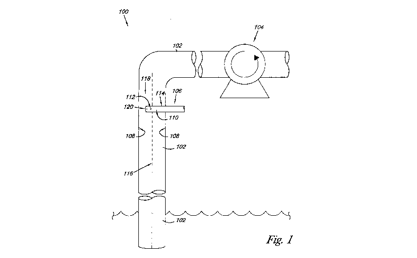
Referring now to Figure 1, there is shown a system 100 according to one
embodiment of the present disclosure for solubilizing a surfactant in scCO2 to
be delivered
to an oil containing reservoir for enhanced oil recovery. As discussed herein,
forming
droplets of the surfactant with a diameter of less than the maximum stable
droplet diameter
in scCO2 may help to better ensure that the surfactant can be completely
solubilized into the
scCO2 prior to being delivered into the oil containing reservoir for enhanced
oil recovery.
For example, the system 100 may help to ensure that the surfactant will be
solubilized into
the scCO2 within a downhole distances in the range of 1500 to 7000 feet,
corresponding to
nominal residence times of 140 to 670 seconds. As such, in one or more
embodiments
producing droplet diameters of the surfactant that have a residence time of
less than 700
seconds in the scCO2 is preferred.
7
CA 02801360 2012-12-03
WO 2011/152876 PCT/US2011/001006
As illustrated, the system 100 includes piping 102 containing scCO2, a pump
104 to
turbulently convey the scCO2 through the piping 102, and an injector 106
associated with
the piping 102. In one or more embodiments, the turbulent flow of the scCO2 in
the piping
102 and the configuration of the injector 106 help to decrease the mass-
transfer resistance of
the surfactant relative the scCO2 by a reduction of the diffusion paths, while
simultaneously
increasing the surface area of the surfactant for mass transfer (e.g., forming
droplets of the
surfactant with a diameter of less than the maximum stable droplet diameter in
prevailing
scCO2 conditions). In one or more embodiments, the configuration of the
injector 106
ensures that the surfactant is injected into the turbulent flow of the SCCO2
(e.g., away from a
wall 108 of the piping 102) so as to produce droplets of the surfactant having
a diameter less
than the maximum stable droplet diameter for the prevailing scCO2 conditions.
Based on
the discussion provided herein, droplets of surfactant smaller than the
maximum stable
droplet diameter for the prevailing scCO2 conditions may allow for the
complete
solubilization of the surfactant into the scCO2 along the available length of
the downhole
piping 102.
For one or more embodiments, the injector 106 associated with the piping 102
can
have a number of different configurations, as discussed herein. For example,
as illustrated
in Figure 1, the injector 106 can have a tubular configuration that extends
through a wall
108 of the piping 102. In one or more embodiments, the injector 106 includes a
manifold
110 and a surface defining a port 112 that extends through the wall 114 of the
injector 106
from the manifold 110. For the various embodiments, the injector 106 conveys
the
surfactant through the manifold 110 and the port 112 to inject a jet of the
surfactant into the
turbulent flow of the scCO2 inside the piping 102. In one or more embodiments,
the
surfactant is injected at a predetermined volumetric value of relative the
volumetric flow
rate of the scCO2.
As illustrated, the port 112 of the injector 106 is positioned away from the
wall 108
of the piping 102, as injecting the surfactant near or at the wall may lead to
"hugging" of the
surfactant such that the desired droplet mean diameter may not be achieved. In
one or more
embodiments, the port 112 of the injector 106 can be positioned at
approximately a radial
center line 116 of the piping 102. In one or more embodiments, additional
configurations of
the injector 106 allow for the port 112 to be located away from the center
line 116 so as to
be closer to, but not at, the wall 108 of the piping 102.
In one or more embodiments, the port 112 of the injector 106 introduces a jet
of the
surfactant in a direction that cuts across the longitudinal flow direction 118
of the scCO2
8
CA 02801360 2012-12-03
WO 2011/152876 PCT/US2011/001006
towards the wall of the piping 108. In one or more embodiments, the port 112
of the
injector 106 introduces the jet of the surfactant perpendicular to the radial
center line 116 of
the piping 102 and the longitudinal flow direction 118 of the scCO2. In one or
more
embodiments, the port 112 of the injector 106 introduces the jet of the
surfactant at a non-
perpendicular angle relative to the radial center line 116 of the piping 102
and the
longitudinal flow direction 118 of the scCO2. For one or more embodiments, the
jet of the
surfactant is physically and volumetrically sized to be introduced into the
stream of the
scCO2 so as to provide rapid mixing and to create the droplet diameter of the
surfactant in
the scCO2 that helps to ensure solubilization into the prevailing turbulent
flow condition of
the scCO2.
In one or more embodiments, a methodology used to characterize the jet flow
through the port 112 into the cross flow of the scCO2 can be defined by a Jet
Mixing
Number (JMN) calculated by Equation 1:
jet velocity in port 112 diameter of port 112
Jet Mixing Number = Equation 1
velocity in piping 102 radius of piping 102
As used herein, the value of the JMN provides an indication whether the jet
flow of the
surfactant through the port 112 permeates across the longitudinal flow
direction 118 and
onto the wall of the piping 102. For example, for JMN values from 0.01 to 1.0
allow the jet
flow of the surfactant to permeate the longitudinal flow direction 118 of the
scCO2, turning
before it hits the wall 108 of the piping 102. For JMN values of 1.0 or
greater the jet flow
permeates the longitudinal flow direction 118 of the scCO2 to contact the wall
108 of the
piping 102, which can result in back mixing with subsequent "hugging" of the
wall by the
surfactant. Preferably, the injector 106 conveys the surfactant through the
port 112 to inject
the surfactant into the turbulent flow of the supercritical fluid so as to
achieve a JMN of
0.01 to 1.0, where a JMN of 0.07 is one specifically preferred value.
In one or more embodiments, both the size and the cross-sectional shape of the
port
112 can be selected to best achieve the desired JMN with the piping 102 and
the velocity of
the scCO2. For example, the port 112 can have one of a number of different
cross-sectional
shapes. These include, but are not limited to, circular, non-circular (e.g.,
elliptical),
triangular, rectangular and other polygonal shapes, among others. In one
embodiment, for
example, the port 112 can have a circular cross-sectional shape having a
diameter of about 1
millimeter.
9
CA 02801360 2012-12-03
WO 2011/152876 PCT/US2011/001006
Other sizes are possible, where the JMN along with other values of the
velocity of
the scCO2 and the surfactant and the diameter of the piping 102 can be used to
determine
size (e.g., diameter) of the port 112.
In addition, the walls defining the openings can be tapered (e.g., beveled) or
un-
tapered (i.e., cross-sectional area changes or does not change along the depth
of the port
112). In an additional embodiment, when two or more ports 112 are present (as
will be
more fully discussed herein), the cross-sectional shapes and/or sizes need not
be constant
for the ports 112. For example, the ports 112 can have a variety of cross-
sectional shapes,
sizes, directions relative the radial center line 116 and profiles for a given
injector 106.
In one or more embodiments, the injector 106 can be formed from a corrosion
resistant material. As used herein, corrosion resistant materials include
those materials that
resist reacting to or do not react with the surfactant and/or the scCO2 used
with the system
for enhanced oil recovery. Examples of suitable corrosion resistant materials
used to form
the injector 106 can include titanium, titanium alloys (e.g., grade 7
titanium), austenitic
stainless steels, ferritic stainless steels, precipitation hardenable
stainless steel, among
others.
In one or more embodiments, the piping 102 can have a circular cross-sectional
shape taken perpendicular to the radial center line 116. Other cross-sectional
shapes are
possible. In addition, the piping 102 can have a constant diameter in the
vicinity of the
injector 106. In one or more embodiments, the piping 102 can include a
venturi. For
example, a venturi can be included immediately upstream and/or downstream of
the injector
106. In one or more embodiments, the injector 106 can be positioned along the
length of a
venturi (e.g., the port 112 is located in the venturi of the piping 102).
In one or more embodiments, the pump 104 can provide the supercritical fluid
with
the turbulent flow (e.g., Reynolds number of at least 2100) through at least a
portion of the
piping 102. Examples of such pumps include, but are not limited to, a
pneumatic booster
pump, among others. As discussed herein, scCO2 is used in the system 100.
Other
supercritical fluids besides or in addition to ScCO2 could also be used in the
system 100.
As the example of Figure 1 illustrates, the port 112 on injector 106 can be a
single
port 112 located at either the radial surface of the injector 106 (as
illustrated in Figure 1) or
at the end 120 of the injector 106. Additional embodiments of the injector 106
discussed
herein, however, can include more than one port 112. As will be appreciated,
the number,
the size, the spacing and/or the distribution of the ports 112 can be
configured to ensure
mechanical integrity of the injector 106 and to ensure that the surfactant
injected through
CA 02801360 2012-12-03
WO 2011/152876 PCT/US2011/001006
the port 112 does not impinges on the wall 108 of the piping 102 (i.e., the
JMN is from 0.01
to 1.0).
In one or more embodiments, examples of surfactants useful with the present
disclosure include those found in U.S. Pat. Nos. 6,686,438 to Beckman and
5,789,505 to
Wilkinson, and the U.S. Pat. Application entitled "Compositions for Oil
Recovery and
Methods of Their Use," U.S. Pat. Application Serial No. 61/196,235.
Figure 2 provides an illustration of an addition embodiment of the system 200
according to the present disclosure. In one or more embodiments, the injector
206 includes
two or more ports 212 that are selected to provide sufficient segmentation and
droplet
diameter of the surfactant in the scCO2 flow, as discussed herein. In
addition, each'of the
ports 212 can be independently oriented relative the radial center line 216 as
discussed
herein (e.g., oriented to produce a jet perpendicular and/or non-perpendicular
to the
longitudinal flow direction 218 of the scCO2). Likewise, each of the ports 212
can
independently have cross-sectional shapes and/or sizes as discussed herein.
Figure 2 further illustrates an embodiment of the system 200 that includes a
fitting
222 that can be used to add energy dissipation to assist in surfactant droplet
solubilization
(e.g., increase local turbulence of the scCO2 in an around the ports 312 of
the injector 204)
and/or to served to make the system 200 more compact. As illustrated, the
piping 202
includes an elbow 224 upstream of the injector 202, where the injector 202
passes through
the volume defined by the wall of the elbow 224.
The embodiment of the system 200 illustrated in Figure 2 also provides an
example
in which the ports 212 are uniformly (e.g., concentrically) arranged relative
the radial center
line 216 of the region of piping 202 when the injector 206 is concentrically
located with the
radial center line 216. In an alternative embodiment, the ports 212 can be non-
uniformly
distributed (e.g., eccentrically) arranged relative the radial center line 216
of the region of
piping 202 where the injector 206 is positioned eccentric relative the radial
center line 216.
Other configurations are possible.
The manifold 210 of injector 206 also has a sufficient volume to ensure
uniform
flow from each of the ports 212 of the injector 206 (e.g., the manifold 210 of
the injector
206 has a relatively large cross-sectional area relative to the cross-
sectional area of each
port 212 so that the pressure variations in the manifold 210 are negligible).
For example,
the pressure drop for the surfactant across each of the ports 212 can be
greater than 10 times
the pressure drop over the length of the manifold 210. This allows for uniform
surfactant
11
CA 02801360 2012-12-03
WO 2011/152876 PCT/US2011/001006
flow from each of the ports 212 while avoiding any issues of backflow of the
scCO2 into the
injector 202.
Figure 3 provides an illustration of an addition embodiment of the system 300
according to the present disclosure. In one or more embodiments, the injector
306 includes
two or more arms 326 (e.g., forming a cross pattern), where each arm 326
includes two or
more ports 312 that are selected to provide sufficient segmentation and
droplet diameter of
the surfactant in the ScCO2 flow, as discussed herein. As discussed herein,
.each of the ports
312 can be independently oriented relative the radial center line 316, and can
independently
have cross-sectional shapes and/or sizes as discussed herein.
The system 300 includes a fitting 322, as discussed herein. In addition, the
system
300 further includes a static mixer 328 in the piping 302. In turbulent flow,
the use of the
static*mixer 328 helps to augment the occurring turbulence to accelerate
mixing. Types of
static mixers can include, but are not limited to, KVM, HEV and SMV type
static mixers,
among others. Wall-mounted tabs and/or vanes can also be used to help augment
the
occurring turbulence to accelerate mixing in the system 300. Other alterations
in the flow
path along the piping 302 can also be included. These can include, but are not
limited to,
single or multiple hole orifice plant(s), half-moon orifice plates, screens,
or other restricting
devices that could potentially enhance droplet dispersion.
Figure 4 provides an example of an alteration used in the flow path along the
piping
402. As illustrated, the piping 402 can include a hollow conical insert 430
positioned
relative the injector 406. In the embodiment of Figure 4, the injector 406
includes a sparger
ring, where the ports 412 can be located on an inner ring surface and/or an
outer ring
surface (Figure 4 provides in illustration with the ports 412 on the inner
ring surface).
For the various embodiments, the hollow conical insert 430 can help to
accelerate
the flow of the scCO2 in the vicinity of the ports 412. In one or more
embodiments, the
hollow conical insert 430 can have linear walls, as illustrated, to provide
what is essentially
a cone segment. In one or more embodiments, the hollow conical insert 430 can
have walls
that curve at least along a portion of their length, to provide for more of a
bell shaped
structure. Other shapes are possible.
In one or more embodiments, the hollow conical insert 430 can be positioned
upstream of the injector 406 with the outlet of the conical insert 430 aligned
with the one or
more ports 412. The illustration provided in Figure 4 has the hollow conical
insert 430
flush with a leading edge of the injector 406. In one or more embodiments;
however, the
12
CA 02801360 2012-12-03
WO 2011/152876 PCT/US2011/001006
hollow conical insert 430 could be located inside the area defined by the
sparger ring of the
injector 430 or outside the area defined by the sparger ring of the injector
430.
In addition to providing a surfactant into the stream of scCO2 according to
the
various embodiments of the present disclosure, other liquid additives could
also be injected,
with or without the surfactant, using the injector of the present disclosure.
Such liquids
could include, but are not limited to, corrosion inhibitors, scale inhibitors,
biocides, hydrate
inhibitors, and demulsifiers, among others.
Example
The following example provides an illustration and an approach to determining
the
maximum stable droplet diameter, mass transfer rates, and solubilization times
for an
exemplary surfactant in a scCO2. Results from this analysis can provide for
optimization of
the droplet diameter for the surfactant of less than a maximum stable droplet
diameter
calculated for a prevailing turbulent flow condition of the ScCO2.
According to the present example, parameters are assigned for a mass transfer
coefficient kL range, surfactant-scCO2 interfacial tension 6, and surfactant
solubility in
ScCO2. The maximum stable droplet diameter due to turbulence, required to
calculate the
interfacial area per volume "a", was estimated based on the friction factor,
flow conditions,
and physical properties found during this exemplary process and a system for
solubilizing a
surfactant into scCO2 for use in enhanced oil recovery.
The bases for calculations for solubilizing the surfactant into the scCO2 are
provided
as follows. For the scCO2 the pressure was take at 2000 psi with a temperature
of 40 C, a
flow rate of 11 million (MM) standard cubic foot per day (@ 0.11 lb/scf =>
14.0 lb/s = 6.4
kg/s), a density 800 kg/m3, and a viscosity of 0.1 cP. For the surfactant
phase, the surfactant
was Experimental Surfactant 08-1015 supplied by the Dow Chemical Company, used
neat
(e.g., no solvent added), with a number average molecular weight of 372, with
a flowrate
based on a concentration of 0.1 wt% in scCO2 after mixing, having a density
1100 kg/m3, a
viscosity 50 cP, and a saturation concentration in scCO2 2000 parts per
million (ppm). The
piping system was taken as follows, a downhole piping having a diameter of
2.212 inches
(5.618 cm), a roughness of the piping wall of 0.00021 inch (0.00533 mm) and a
length of
7000 feet (2133.6 meters) of downhole depth for the initial trials. The
velocity of the scCO2
in the tubing is 3.2 m/s. The resulting Reynolds number (Re) is calculated to
be 1.45x10⁶,
which provides for turbulent flow. The maximum stable droplet diameter of the
surfactant
formed in the turbulent flow of the scCO2 for use in enhanced oil recovery was
estimated at
13
CA 02801360 2012-12-03
WO 2011/152876 PCT/US2011/001006
700 .tm and the volume-to-area (Sauter) mean at 470 m. The following is a
discussion of
how these values were evaluated and then calculated.
A standard film model for mass transfer is used in the present calculations:
dC scCO2
surf sccoz - C scCoz lk
' Equation 2
dt = kL a(Csurf,sal surf,bu
MT
where the left hand side of the equation is the molar flow rate (per volume)
of surfactant
from droplets to the scCO2 phase, kL is the mass transfer coefficient, "a" is
the droplet
interfacial area per unit volume, CscC 2 is the saturation concentration of
surfactant in
scCO2, and C.sõ hulk is the bulk concentration of surfactant in the scCO2 at a
given time
(length) in the piping. The equation is solved for CscC02 Note that since the
surfactant is
surf,bulk '
neat, i.e. solvent-free, mass transfer resistance is not expected in the
surfactant phase
because no concentration gradient can arise there. Hence the kL in the above
equation is the
value for transport limitations on the SCCO2 side of the phase boundary.
From the literature, it is known that the mass transfer coefficients of pure a-
tocopherol (Vitamin E, MW 430) in a scCO2 system have values that range from
1.00 x10⁵
m/s for a kL minimum to a kL maximum of 3.00x10"5 m/s. Reynolds numbers used
in
studying these mass transfer values ranged from 200 to 3000 in channel flow.
From this
study, a linear log-log plot of kL versus Reynolds number for each scCO2
density tested
provided that for a scCO2 density of about 800 kg/m3, the mass transfer
coefficient was
about 3x10⁵ m/s at a Re of 3000 in the channel. Following Kawase et al, the
mass transfer
coefficient is expected to grow with the 0.25 power of the energy dissipation
rate 6
(Kawase, Y., Halard, B., Moo-Young, M., "Theoretical Prediction of Volumetric
Mass
Transfer Coefficients in Bubble Columns for Newtonian and Non-Newtonian
Fluids,"
Chem. Eng. Sci., 42 1609-1617 (1987)). For pipe flow, c is proportional to the
square of the
liquid velocity. Hence the impact in extrapolating from a Reynolds number of
3000 to
1.45x10⁶ used in the present calculations results in a mass transfer
coefficient extrapolation
from 3x 10⁻⁵ to 6.6x 10 m/s.
Since this is a rather large extrapolation, another method was used to verify
this
value. Higbie's penetration theory for gas-liquid mass transfer (Higbie, R.,
"The Rate of
Absorption of a Pure Gas into a Still Liquid during Short Periods of
Exposure," Trans. Am.
Inst. Chem Eng., 31, 365-389(1935) and Danckwerts, P.V., Kennedy A. M.,
"Kinetics of
liquid-film process in gas absorption, Part 1: Models of the absorption
process," Trans.
Inst. Chem Engrs, 32, s49-s53 (1954)) supposes that an element of fluid is
exposed to the
14
CA 02801360 2012-12-03
WO 2011/152876 PCT/US2011/001006
phase interface for time te, then is replaced with a new fluid element. When
Kalmogoroff's
time scale is used for to (Kawase, Y., Halard, B., Moo-Young, M., "Theoretical
Prediction
of Volumetric Mass Transfer Coefficients in Bubble Columns for Newtonian and
Non-
Newtonian Fluids," Chem. Eng. Sci., 42 1609-1617 (1987)), Higbie's equation
for
calculation of kL becomes:
2 v- 1/4
kL = DAB (V) Equation 3
where DAB is the diffusion coefficient of the solute in the scCO2, c is the
energy dissipation
rate in the fluid, and v is the kinematic viscosity. While the equation was
derived for gas-
liquid systems, it would seem that the derivation should apply to liquid-
supercritical fluid
systems as well, as long as the continuous phase (where the turbulence is
being dissipated)
is rate limiting for the mass transfer.
Equation 3 requires an estimate for the diffusion coefficient. Diffusion
coefficients
in supercritical fluids were studied by Tan (Tan, C.-S., Liang, S.-K., Liou,
D.-C., "Fluid-
Solid Mass Transfer in a Supercritical Fluid Extractor," Chem. Eng. J., 38, 17-
22 (1988))
for essential oils. For 0-naphthol in scCO2, for instance, at same conditions
for the
surfactant and scCO2 provided above, the diffusion coefficient falls very
close to lx10-8
m2/s, and order of magnitude larger than is typical in liquids. This is in
general agreement
with trends shown by Debenedetti & Reid (Debenedetti, P.G., Reid, R.C.,
"Diffusion and
Mass Transfer in Supercritical Fluids," AIChE J., 32, 2034-2046 (1986)) for 0-
napththol
and benzoic acid, measured at higher temperatures and pressures. Surfactants
used in
enhanced oil recovery processes, such as those provided herein, will likely
have a lower
diffusion coefficient due to their larger molecular weights MW (e.g., 772 vs.
144). The
diffusion coefficient is expected to vary with the inverse of the molecular
radius by the
Stokes-Einstein relation (Atkins, P.W., Physical Chemistry, 2nd ed., W. H.
Freeman & Co.,
San Francisco, 1982).
If r for the surfactant is conservatively taken to be about 5 times that of (3-
naphthol,
a diffusion coefficient of 2x10⁻⁹ m2/s is calculated. With e calculated as 4.0
W/kg (the
estimation of which is discussed more fully below) and v as 1.25x10⁻⁷ m2/s,
the value of kL
is then calculated to be 3.5x10⁻³ m/s, some 5 times larger than extrapolated
from the E1!4 rule
from Zehnder's data for Vitamin E. Hence it can be inferred that the previous
extrapolated
value of 6x10 m/s is not excessive and is most probably conservative.
General correlations for droplet diameter commonly correlate with the
continuous
phase Sherwood number, She,
CA 02801360 2012-12-03
WO 2011/152876 PCT/US2011/001006
Shc = kLd32 Equation 4
The lower limiting value of She, derived by Langmuir (Kumar, A., Hartland, S.,
"Correlations for prediction of mass transfer coefficients in single drop
systems and liquid-
liquid extraction columns," Trans. IChemE, 77 A 372-384, July 1999 and
Langmuir, I.,
"The Evaporation of Small Spheres," Phys. Rev., 12, 368-370, 1918) for
stagnant
conditions, is a value of 2. This represents a lower limit to the mass
transfer due to the
absence of convection. Taking the diffusion coefficient derived above and a
droplet
diameter of 500 m, kL is calculated as 8x10⁻⁶ m/s, nearly two orders of
magnitude smaller
than previous low-side extrapolated value and in line with expectations for
stagnant
conditions.
Interfacial Tension, o
The interfacial tension is a parameter needed in order to calculate the
maximum
stable.droplet diameter in a flow field. Values of components in the
literature vary, but no
data were found for a pure surfactant in scCO2. The closest found was from
Galy et al.
(Galy, J., Sawada,K., Fournel, B., Lacroix-Desmazes, P., Lagerge, S., Persin,
M.,
"Decontamination of solid substrates using supercritical carbon dioxide -
Application with
trade hydrocarbonated surfactants," J. of Supercritical Fluids, 42, 69-79
(2007)) who
studied EO-PO triblock copolymer surfactants of various molecular weights in
the system
water-scCO2. Without surfactant, the interfacial tension is near 10 dyne/cm at
the pressure
of interest in this study. The values with added surfactant were measured in
the range of 2 -
dynes/cm. The value 10 dyne/cm is taken as a conservative estimate.
Saturation Concentration, CS`coz
surjsat
The surfactant used in the present calculations is known to be soluble in
scCO2 at
1000 ppm. The saturation value was estimated to be 2000 ppm. For comparison,
the results
of Haruki et al. (Haruki, M., Yawata, H., Nishimoto, M., Tanto, M., Kihara,
S., Takishima,
S., "Study on phase behaviors of supercritical CO2 including surfactant and
water," Fluid
Phase Equilibria, 261, 92-98 (2007)) show the solubility of a branched
surfactant to be near
4000 ppm in scCO2. The surfactant of Haruki et al. was polyethylene oxide-
2,6,8-
trimethyl-4-nonyl ether (TMN) with number average MW of 420. The number
average
MW of the surfactant used in the present calculations is 772. Hence the
estimated
saturation value of 2000 ppm is consistent with Haruki et al.
16
CA 02801360 2012-12-03
WO 2011/152876 PCT/US2011/001006
Calculation of maximum stable droplet diameter of the surfactant in scCO2
The calculation of the maximum stable droplet diameter of the surfactant in
scCO2 is
based on the following model for a slice of scCO2 fluid having surfactants
droplets moving
through an injection tube. Take a slice of scCO2 fluid of diameter D,
differential width 1,
containing surfactants droplets of diameter dp with volumetric phase fraction
4i for phase j.
The surfactant droplets will shrink in mass as the surfactant is transported
into the scCO2
phase. The following are assumptions for transport of the surfactant droplets:
(1) surfactant
droplet coalescence and fragmentation are ignored, due to the relatively low
phase fraction
of surfactant involved; (2) transport resistance is on the scCO2 side since
the surfactant
phase is neat, hence there can be no concentration gradient in that phase and
(3) surfactant
droplets are convected with the same velocity as scCO2. Based at least in part
on these
assumptions, the following equations can be written:
volume of surfactant phase
volume of all phases Equation 5
~su~ "~" =
t k a(CS`C02 _ CscCoz
Fraction surfactant transferred = Fsurf (t) = f o L `SUS S ` S:~rl,bulk dt
Equation 6
Csurf (O)Y'su,f (O)
1/3
droplet diameter = d p (t) = d p (0 FSUf Equation 7
Osurf (0)
z
Vsccoz = (1- Osurf ~ 4 1 Equation 8
dO _ d V org 7r d (npd z) = M Equation 9
dt dt V' ' 4V' ' dt P V` t porg
where "M is the net mass transfer (mass per time) between the phases. This is
calculated
from the mass transfer coefficient equation:
Sccoz oq M
cC- dcsu dt V = J kLa(CS Oat - C urf'bulk ) = MW Equation 10
surf
Surfactant Maximum Stable Droplet Diameter Calculation
Hanzevack & Demetriou looked at droplet diameter distributions after short
lengths
of pipe, including straight runs and elbows (Hanzevack, E.L., Demetriou, G.D.,
"Effect of
Velocity and Pipeline Configuration on Dispersion in Turbulent Hydrocarbon-
Water Flow
17
CA 02801360 2012-12-03
WO 2011/152876 PCT/US2011/001006
using Laser Image Processing," Int. J. Multiphase Flow, 15, 985-996 (1989)).
For a length
of 80 diameters of straight horizontal pipe (8.2 cm diameter), the maximum
droplet
diameter was found to be 1600 m at a velocity exceeding 2 m/s. Most droplets
were less
than 500 m in diameter. This provides an upper bound to maximum stable
droplet
diameter in a turbulent pipe.
For the exemplary process and system provided herein the Reynolds number
Dvp/,u, where p is the average density, u is the average viscosity, v is the
average velocity,
and D is the pipe diameter) is 1.45x10⁶, showing that the system is highly
turbulent. The
velocity in the downhole piping is 3.2 m/s, showing that the residence time is
140 seconds
for 1500 ft (457 m) of depth and 670 seconds for 7000 ft (2130 m) of depth.
The maximum stable droplet diameter was shown by Davies to equal
3/5
dmax = C f -zls Equation 11
PC
where C is a constant in the range of 0.5 -1 for standard mixing devices (0.68
for pipe and
static mixer flows), o is the surface tension, p, is the density of the
continuous (scCO2)
phase, and e is again the energy dissipation rate in the pipe (Davies, J.T.,
"A Physical
Interpretation of Drop Sizes in Homogenizers and Agitated Tanks, Including the
Dispersion
of Viscous Oils," Chem. Eng. Sci., 42, 1671-1676 (1987)). The mean droplet
diameter is
normally taken to be 2/3 of the d,,,ax. This expression is for droplet
viscosities on the order
of 1 cP. A viscosity correction is applied based on the data of Berkman &
Calabrese,
(equation 17 of Davies):
3/5 3/5
dmax = C 6 -2/5 1 + 1.4v ,Ud Equation 12
PC 6
where v' is the fluctuating velocity, taken as 5% of the mean velocity, hence
0.16 m/s for
the flow of scCO2 used herein. The viscosity correction amounts to a 56%
increase in d,,,
over a water-like viscosity dispersed fluid.
In order to estimate the energy dissipation rate, the pressure drop through
the
downhole piping is required. Based on the aforementioned roughness factor of
0.00021
inches and Reynolds number of 1.45x10⁶, the friction factor f was taken as
0.0033
(McCabe, W.L., Smith, J.C., Unit Operations of Chemical Engineering, 3rd ed.,
1976). The
pressure drop equation for open pipe defines the friction factor:
18
CA 02801360 2012-12-03
WO 2011/152876 PCT/US2011/001006
z
Op = 2fALpv Equation 13
&D
The hydraulic power applied to the fluid is the pressure drop times the
volumetric flow:
P = ApV = Op m Equation 14
P
If the pressure drop is calculated for a unit amount of pipe length, the mass
contained in that
length of pipe receives the energy dissipation. Hence a power per mass (energy
dissipation
rate) is calculated:
_ P
E a DZLP Equation 15
For the conditions of the exemplary process and system, the energy dissipation
rates is
calculated to be 4.0 W/kg. Hence, taking C equal to 0.68, a as 10 dyne/cm, and
p, as 800
kg/m3, d,,,,, is calculated to be 700 m, which is consistent with Hanzevack
et al.
(Hanzevack, E.L., Demetriou, G.D., "Effect of Velocity and Pipeline
Configuration on
Dispersion in Turbulent Hydrocarbon-Water Flow using Laser Image Processing,"
Int. J.
Multiphase Flow, 15, 985-996 (1989)). The volume-to-area (Sauter mean)
diameter, d32 is
then taken as 2/3rds of this value, which is 470 m.
The estimated parameters and droplet diameter were then used with the 1-
Dimensional (1-D) mass transfer model as expressed in Equation 2. With a high
end
estimate of kL, generated from Higbie's penetration model using the
Kolmolgoroff time
scale for renewal rate, no problems with surfactant solubilization should
occur for the
downhole distances considered. The half-life of the biggest droplets is about
15 seconds,
equivalent to 160 ft of piping at nominal velocity.
Figures 5 through 7 show the 1 -D mass transfer calculations for droplet
diameter of
700 m, 470 m, and 100 m, respectively, into scCO2. The calculations are
based on
Equations 5 to 10, and include curves for the low and high-end estimates of
kL, 6.6x10⁴ and
3.5x10⁻³ m/s. For the Figures, 140 seconds is the residence time at 1500 ft
downhole depth
and the curves with the high value of kL show that all drops will solubilize
within this time
frame. For the low value of kL, however, a fraction of the surfactant droplets
may be left at
the 140 second point. Figure 6 shows that the volume fraction of droplets is
820 ppm at 140
seconds, showing 18% is yet to be dissolved. This is representative of the
mixture as a
whole. In this case 350 seconds is needed to ensure full solubilization,
equivalent to 3700
feet of pipe at nominal velocity.
19
CA 02801360 2012-12-03
WO 2011/152876 PCT/US2011/001006
Figures 5 and 8 are next used to determine a full solubilization time for the
biggest
surfactant droplets. From these Figures, it can be estimated that about 500
seconds are
required for full solubilization of the surfactant droplets, representing 5300
feet of pipe. At
500 seconds, the 700 m surfactant droplets have shrunk to 1/7 of original
diameter so have
just ('/7)3 = 0.003 of their original mass. The half-life of these droplets is
just under 90
seconds, representing 920 feet of piping. However it must be recognized that
the surfactant
droplets starting with diameter dm do not represent a large fraction of the
total mass. A d32
basis represents the total surface area available in the droplet distribution.
As shown in
Figure 6, 99% of the total mass of the injected surfactant is solubilized in
300 seconds, or
3200 feet.
So, it has been found that using a low end estimate for kL, generated from
extrapolation of data from an analogous species (e.g., Vitamin E) to the
surfactant used in
the above calculations of the present disclosure, it was found that about 3200
feet of piping
length is required to ensure 99% solubilization of the surfactant into the
scCO2. At 1500
feet, the undissolved fraction of the surfactant could be as high as 20%. The
half-life of the
biggest droplets is just under 90 seconds, which is equivalent to about 920
feet of piping.
As appreciated, the above calculations were based on specific conditions for
both the
scCO2 and the surfactant. It is appreciated that as the physical
characteristics of the scCO2
(e.g., density, pressure, temperature, and/or mass flow rate) change so will
the Reynolds
number (e.g., the amount of turbulence) of the scCO2 and in turn the maximum
stable
droplet diameter for the prevailing turbulent flow condition of the SCCO2. In
other words,
the maximum stable droplet diameter for a given surfactant is dependent upon
the prevailing
turbulent flow condition of the SCCO2.
As discussed herein, these maximum stable droplet diameters, however, may not
be
sufficiently small to ensure that the surfactant is solubilized into the scCO2
before the end of
the piping. As discussed herein, the injector(s) of the present disclosure can
help to ensure
that droplet diameter of the surfactant are less than the maximum stable
droplet diameter for
the prevailing turbulent flow condition of the scCO2. The injectors used with
the system of
the present disclosure may allow for the droplets of the surfactant to be
rapidly formed in
and distributed throughout a stream of scCO2 to better ensure that the
surfactant is
completely solubilized into the scCO2 prior to being delivered into an oil
containing
reservoir for enhanced oil recovery.
It is to be understood that the above description has been made in an
illustrative
fashion, and not a restrictive one. Although specific embodiments have been
illustrated and
CA 02801360 2012-12-03
WO 2011/152876 PCT/US2011/001006
described herein, those of ordinary skill in the art will appreciate that
other component
arrangements can be substituted for the specific embodiments shown. The claims
are
intended to cover such adaptations or variations of various embodiments of the
disclosure,
except to the extent limited by the prior art.
In the foregoing Detailed Description, various features are grouped together
in
exemplary embodiments for the purpose of streamlining the disclosure. This
method of
disclosure is not to be interpreted as reflecting an intention that any claim
requires more
features than are expressly recited in the claim. Rather, as the following
claims reflect,
inventive subject matter lies in less than all features of a single disclosed
embodiment.
Thus, the following claims are hereby incorporated into the Detailed
Description, with each
claim standing on its own as a separate embodiment of the invention.
21