Note : Les descriptions sont présentées dans la langue officielle dans laquelle elles ont été soumises.
ASSAY DEVICE HAVING CONTROLLABLE SAMPLE SIZE
Field of the Invention
[0001] The present invention relates to the field of diagnostic
assays, and
in particular to lateral flow assays where an analyte to be detected is
present in
a biological or non-biological sample.
Background
[0002] Diagnostic assays are widespread and central for the
diagnosis,
treatment and management of many diseases. Different types of diagnostic
assays have been developed over the years in order to simplify the detection
of
various analytes in clinical samples such as blood, serum, plasma, urine,
saliva, tissue biopsies, stool, sputum, skin or throat swabs and tissue
samples
or processed tissue samples. These assays are frequently expected to give a
fast and reliable result, while being easy to use and inexpensive to
manufacture. Understandably it is difficult to meet all these requirements in
one and the same assay. In practice, many assays are limited by their speed.
Another important parameter is sensitivity. Recent developments in assay
technology have led to increasingly more sensitive tests that allow detection
of
an analyte in trace quantities as well the detection of disease indicators in
a
sample at the earliest time possible.
[0003] A common type of disposable assay device includes a zone or
area
for receiving the liquid sample, a conjugate zone also known as a reagent
zone,
and a reaction zone also known as a detection zone. These assay devices are
commonly known as lateral flow test strips. They employ a porous material,
e.g.,
nitrocellulose, defining a path for fluid flow capable of supporting capillary
flow.
Examples include those shown in US Patent Nos. 5,559,041, 5,714,389,
5,120,643, and 6,228,660.
[0004] The sample-addition zone frequently consists of a more porous
material, capable of absorbing the sample, and, when separation of blood cells
is
desired, also effective to trap the red blood cells. Examples of such
materials are
fibrous materials, such as paper, fleece, gel or tissue, comprising e.g.
cellulose,
wool, glass fiber, asbestos, synthetic fibers, polymers, or mixtures of the
same.
1
CA 2802645 2019-08-23
[0005] Another type of assay device is a non-porous assay device
having
projections to induce capillary flow. Examples of such assay devices include
the
open lateral flow device as disclosed in PCT International Publication Nos. WO
2003/103835, WO 2005/089082, WO 2005/118139, and WO 2006/137785.
[0006] A known non-porous assay device is shown in Fig. 1. The assay
device 1, has at least one sample addition zone 2, a reagent zone 3, at least
one
detection zone 4, and at least one wicking zone 5. The zones form a flow path
by
which sample flows from the sample addition zone to the wicking zone. Also
included are capture elements, such as antibodies, in the detection zone 4,
capable of binding to the analyte, optionally deposited on the device (such as
by
coating); and a labeled conjugate material also capable of participating in
reactions that will enable determination of the concentration of the analyte,
deposited on the device in the reagent zone, wherein the labeled conjugate
material carries a label for detection in the detection zone. The conjugate
material is dissolved as the sample flows through the reagent zone forming a
conjugate plume of dissolved labeled conjugate material and sample that flows
downstream to the detection zone. As the conjugate plume flows into the
detection zone, the conjugated material will be captured by the capture
elements
such as via a complex of conjugated material and analyte (as in a "sandwich"
assay) or directly (as in a "competitive" assay). Unbound dissolved conjugate
material will be swept past the detection zone into the at least one wicking
zone 5.
Also shown in Fig. 1 are projections or micropillars 7.
[0007] An instrument such as that disclosed in US Patent Publication
Nos.
US20060289787A1 and US 20070231883A1, and US Patent Nos. 7,416,700 and
6,139,800 is able to detect the bound conjugated material in the detection
zone.
Common labels include fluorescent dyes that can be detected by instruments
which excite the fluorescent dyes and incorporate a detector capable of
detecting
the fluorescent dyes.
[0008] The sample size for such typical assay devices as shown in
Fig. 1 are
generally on the order of 200p1. Such a sample size requires a venous blood
draw from a medical professional such as a phlebotomist. There is an
increasing
need for lateral flow devices that are able to function with a much smaller
sample
size to accommodate the amount of blood available from a so-called
"fingerstick"
2
CA 2802645 2019-08-23
blood draw, which is on the order of 25 pl or less. Such a small amount of
sample
is the amount of blood in a drop of blood after pricking a finger tip with a
lancet.
Home blood glucose meters typically use a drop of blood obtained in such a
fashion to provide glucose levels in blood. Such a smaller sample size would
not
require a medical professional to draw the blood and would provide greater
comfort to the patients providing the sample for analysis.
[0009] To reduce sample size required, the dimensions of the
lateral flow
assay devices are reduced to accommodate the smaller sample size. However, it
has been found that reducing the sample size and dimensions of the device
provides inadequate conjugate in the detection zone and accordingly less
signal
that can be read by the instrument (in some instances up to a 5x lower signal)
and poor sensitivity. The inadequate conjugate in the detection zone is
believed
to be due to reduced sample size and inefficient use of the sample in the
device,
amongst other conditions. Another drawback of reducing dimensions is that the
width of the detection zone will also be reduced, again making less signal
available that can be read by the instrument. Also, it has been found that a
smaller device has reduced flow time and conjugate material contact time,
resulting in less binding between the analyte in the sample and the conjugate
material.
[0010] A need continues to exist for smaller sample volume assay
devices
that can accommodate smaller and smaller sample sizes, can accommodate
various samples (such as whole blood), and can provide results with the
required
sensitivity and specificity.
Summary of the Invention
[0011] The present invention is directed to such an assay device.
An
advantage of the smaller sample device according to the subject invention is
the ability to control sample volume using an "interrupting wash". In its
broadest concept, the interrupting wash can be any fluid. Fluids include
reagent fluids (fluids containing a reagent) with a preferred interrupting
fluid
being a wash fluid. An interrupting wash fluid is added at a predetermined
fill
volume on the chip device which controls sample volume and also serves to
wash the detection channel and fill the remaining chip volume.
3
CA 2802645 2019-08-23
[0012]
Accordingly, one aspect of the invention is directed to an assay
device which comprises: a liquid sample addition zone; a
reagent zone
downstream and in fluid communication with the sample addition zone
containing a reagent material; a detection zone in fluid communication with
the
reagent zone having capture elements bound thereto; and a wicking zone in
fluid communication with the detection zone having a capacity to receive
liquid
sample flowing from the detection zone. In the device, the sample addition
zone, the reagent zone, the detection zone and the wicking zone define a fluid
flow path. The device further comprises a reagent addition zone along and in
fluid communication with the fluid flow path downstream of the sample addition
zone and upstream of the detection zone. The "interrupting wash" is added at
this reagent addition zone (a fluid addition zone in its broadest concept) in
accordance with the method of the subject invention.
[0013] Another
aspect of the invention is thus directed to a method of
controlling sample size in an assay device. The method comprises: providing a
liquid sample addition zone; providing a reagent zone downstream and in fluid
communication with the sample addition zone containing a reagent material;
providing a detection zone in fluid communication with the reagent zone; and
providing a wicking zone in fluid communication with the detection zone having
a capacity to receive liquid sample flowing from the detection zone. The
sample addition zone, the reagent zone, the detection zone and the wicking
zone define a fluid flow path. The method includes further providing a reagent
addition zone along and in fluid communication with the fluid flow path
downstream of the sample addition zone and upstream of the detection zone.
The method further comprises adding sample to the sample addition zone,
wherein the sample moves through the fluid flow path; and adding a reagent to
the reagent addition zone, wherein the reagent interupts flow of the sample
through the fluid flow path thereby controlling sample size within the fluid
flow
path. Preferably the reagent added is a wash fluid.
[0014] Yet
another aspect of the invention is directed to a method of
performing an assay on a liquid sample for the detection of one or more
analytes of interest. The method comprises: providing a liquid sample addition
zone; providing a reagent zone downstream and in fluid communication with
4
CA 2802645 2019-08-23
the sample addition zone containing a reagent material; providing a detection
zone in fluid communication with the reagent zone; providing a wicking zone in
fluid communication with the detection zone having a capacity to receive
liquid
sample flowing from the detection zone, wherein the sample addition zone, the
reagent zone, the detection zone and the wicking zone define a fluid flow
path;
and further providing a reagent addition zone along and in fluid communication
with the fluid flow path downstream of the sample addition zone and upstream
of the detection zone. The method further comprises adding a liquid sample
containing the analyte of interest onto the sample addition zone; moving the
sample by capillary action into the reagent zone wherein the sample dissolves
the reagent material; flowing the sample away from the reagent zone with the
dissolved reagent material therein into the detection zone by capillary
action,
wherein the analyte of interest is detected in the detection zone by reading a
signal that is generated; and flowing the sample and any unbound material into
the wicking zone. The method further comprises adding a reagent to the
reagent addition zone, wherein the reagent interupts flow of the sample
through
the fluid flow path thereby controlling sample size within the fluid flow
path.
Preferably the reagent added is a wash fluid.
[0015] Further objects, features and advantages of the present
invention
will be apparent to those skilled in the art from detailed consideration of
the
preferred embodiments that follow.
Brief Description of the Drawings
[0016] Fig. 1 shows a known assay device.
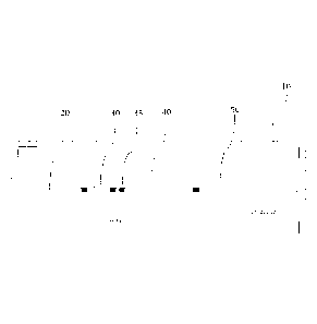
[0017] Fig. 2 shows a schematic view of an assay device according
to
one embodiment of the present invention.
[0018] Fig. 3 shows a schematic view of an assay device according
to
another embodiment of the present invention.
[0019] Fig. 4 shows an exploded view of the layered construction of
an
assay device package according to the present invention.
[0020] Fig. 5 shows mean flow times for whole blood on an assay
device
according to one embodiment of the present invention, with various surfactants
deposited in the sample addition zone.
CA 2802645 2019-08-23
[0021] Fig. 6 shows a comparison of dose response curves of
carbamazepine using whole blood with interrupting wash protocol to results
obtained with plasma.
[0022] Fig. 7 shows a comparison of dose response curves of
phenobarbital using whole blood with interrupting wash protocol to results
obtained with plasma.
[0023] Fig. 8 shows mean flow times for whole blood with a
following
wash on an assay device according to one embodiment of the present
invention, with various NTproBNP levels.
[0024] Fig. 9 shows mean peak area of the fluorescent response
versus
the NTproBNP concentration for each test sample, as well as the dose
response curve obtained for whole blood samples compared to serum samples
of similar NTproBNP concentration, with a following wash on an assay device
according to one embodiment of the present invention.
[0025] Figs. 10 and 11 show sensitivity of different assay device
designs
with NTproBNP as the analyte.
[0026] Fig. 12 is a plot of procalcitonin concentration vs. mean
peak area
using a whole blood sample and a wash.
[0027] Fig. 13 is a plot of procalcitonin concentration vs. mean
peak area
using a whole blood sample.
Detailed Description of Preferred Embodiments
[0028] As used in this specification and the appended claims, the
singular
forms "a", "an" and "the" include plural referents unless the context clearly
dictates otherwise.
[0029] The term "about" as used in connection with a numerical
value
throughout the description and the claims denotes an interval of accuracy,
familiar and acceptable to a person skilled in the art. The interval is
preferably
10%.
[0030] The term "sample" herein means a volume of a liquid,
solution or
suspension, intended to be subjected to qualitative or quantitative
determination of any of its properties, such as the presence or absence of a
component, the concentration of a component, etc. Typical samples in the
6
CA 2802645 2019-08-23
context of the present invention are human or animal bodily fluids such as
blood, plasma, serum, lymph, urine, saliva, semen, amniotic fluid, gastric
fluid,
phlegm, sputum, mucus, tears, stool, etc. Other types of samples are derived
from human or animal tissue samples where the tissue sample has been
processed into a liquid, solution, or suspension to reveal particular tissue
components for examination. The embodiments of the present invention are
applicable to all bodily samples, but preferably to samples of whole blood,
urine
or sputum.
[0031] In other instances, the sample can be related to food
testing,
environmental testing, bio-threat or bio-hazard testing, etc. This is only a
small
example of samples that can be used in the present invention.
[0032] In the present invention, the determination based on lateral
flow of
a sample and the interaction of components present in the sample with
reagents present in the device or added to the device during the procedure and
detection of such interaction, either qualitatively or quantitatively, may be
for
any purpose, such as diagnostic purposes. Such tests are often referred to as
lateral flow assays.
[0033] Examples of diagnostic determinations include, but are not
limited
to, the determination of analytes, also called markers, specific for different
disorders, e.g. chronic metabolic disorders, such as blood glucose, blood
ketones, urine glucose (diabetes), blood cholesterol (atherosclerosis,
obesitas,
etc); markers of other specific diseases, e.g. acute diseases, such as
coronary
infarct markers (e.g. troponin-T, NT-proBNP), markers of thyroid function
(e.g.
determination of thyroid stimulating hormone (TSH)), markers of viral
infections
(the use of lateral flow immunoassays for the detection of specific viral
antibodies); etc.
[0034] Yet another important field is the field of companion
diagnostics
where a therapeutic agent, such as a drug, is administered to an individual in
need of such a drug. An appropriate assay is then conducted to determine the
level of an appropriate marker to determine whether the drug is having its
desired effect. Alternatively, the assay device of the present invention can
be
used prior to administration of a therapeutic agent to determine if the agent
will
help the individual in need.
7
CA 2802645 2019-08-23
[0035] Yet another important field is that of drug tests, for easy
and rapid
detection of drugs and drug metabolites indicating drug abuse; such as the
determination of specific drugs and drug metabolites (e.g. THC) in urine
samples etc.
[0036] The term "analyte" is used as a synonym of the term "marker"
and
intended to encompass any chemical or biological substance that is measured
quantitatively or qualitatively and can include small molecules, proteins,
antibodies, DNA, RNA, nucleic acids, virus components or intact viruses,
bacteria components or intact bacteria, cellular components or intact cells
and
complexes and derivatives thereof.
[0037] The terms "zone", "area" and "site" are used in the context
of this
description, examples and claims to define parts of the fluid flow path on a
substrate, either in prior art devices or in a device according to an
embodiment
of the invention.
[0038] The term "reaction" is used to define any reaction, which
takes
place between components of a sample and at least one reagent or reagents
on or in the substrate, or between two or more components present in the
sample. The term "reaction" is in particular used to define the reaction,
taking
place between an analyte and a reagent as part of the qualitative or
quantitative determination of the analyte.
[0039] The term "substrate" means the carrier or matrix to which a
sample
is added, and on or in which the determination is performed, or where the
reaction between analyte and reagent takes place.
[0040] The present invention is directed to a lateral flow assay
device for
determining the presence or amount of at least one analyte. Figs. 2 and 3
show schematic views of preferred embodiments of such devices according to
the invention. The assay device 10, has at least one sample addition zone 20,
at least one reagent zone 30, at least one detection zone 40, and at least one
wicking zone 50. The zones form a flow path by which sample flows from the
sample addition zone to the wicking zone. The assay device also includes at
least one reagent addition zone 35, preferably located between the reagent
zone and the detection zone.
8
CA 2802645 2019-08-23
[0041] Components of the assay device (i.e., a physical structure
of the
device whether or not a discrete piece from other parts of the device) can be
prepared from copolymers, blends, laminates, metallized foils, metallized
films
or metals. Alternatively, device components can be prepared from copolymers,
blends, laminates, metallized foils, metallized films or metals deposited on
one
of the following materials: polyolefins, polyesters, styrene containing
polymers,
polycarbonate, acrylic polymers, chlorine containing polymers, acetal
homopolymers and copolymers, cellulosics and their esters, cellulose nitrate,
fluorine containing polymers, polyamides, polyimides, polymethylmethacrylates,
sulfur containing polymers, polyurethanes, silicon containing polymers, glass,
and ceramic materials. Alternatively, components of the device are made with
a plastic, elastomer, latex, silicon chip, or metal; the elastomer can
comprise
polyethylene, polypropylene, polystyrene, polyacrylates, silicon elastomers,
or
latex. Alternatively, components of the device can be prepared from latex,
polystyrene latex or hydrophobic polymers; the hydrophobic polymer can
comprise polypropylene, polyethylene, or polyester. Alternatively, components
of the device can comprise TEFLON , polystyrene, polyacrylate, or
polycarbonate. Alternatively, device components are made from plastics which
are capable of being embossed, milled or injection molded or from surfaces of
copper, silver and gold films upon which may be adsorbed various long chain
alkanethiols. The structures of plastic which are capable of being milled or
injection molded can comprise a polystyrene, a polycarbonate, or a
polyacrylate. In a particularly preferred embodiment, the assay device is
injection molded from a cyclo olefin polymer, such as those sold under the
name Zeonor . Preferred injection molding techniques are described in U.S.
Patent Nos. 6,372,542, 6,733,682, 6,811,736, 6,884,370, and 6,733,682.
[0042] The flow path can include open or closed paths, grooves, and
capillaries. Preferably the flow path comprises a lateral flow path of
adjacent
projections, having a size, shape and mutual spacing such that capillary flow
is
sustained through the flow path. In one embodiment, the flow path is in a
channel within the substrate having a bottom surface and side walls. In this
embodiment, the projections protrude from the bottom surface of the channel.
The side walls may or may not contribute to the capillary action of the
liquid. If
9
CA 2802645 2019-08-23
the sidewalls do not contribute to the capillary action of the liquid, then a
gap
can be provided between the outermost projections and the sidewalls to keep
the liquid contained in the flow path defined by the projections. Fig. 1 shows
projections 7.
[0043] In one embodiment the flow path is at least partially open.
In
another embodiment the flow path is entirely open. Open means that there is
no lid or cover at a capillary distance. Thus the lid, if present as a
physical
protection for the flow path, does not contribute to the capillary flow in the
flow
path. An open lateral flow path is described for example in the following PCT
International Publication Nos. WO 2003/103835, WO 2005/089082; WO
2005/118139; WO 2006/137785; and WO 2007/149042. The projections have
a height (H), diameter (D) and a distance or distances between the projections
(t1, t2) such, that lateral capillary flow of the fluid, such as plasma,
preferably
human plasma, in the zone is achieved. These dimensions are shown in US
Patent Publication No. 2006/0285996. In addition to optimizing the above-
mentioned height, diameter and a distance or distances between the
projections, the projections may be given a desired chemical, biological or
physical functionality, e.g. by modifying the surface of the projections. In
one
embodiment, the projections have a height in the interval of about 15 to about
150 pm, preferably about 30 to about 100 pm, a diameter of about 10 to about
160 pm, preferably about 40 to about 100 pm, and a gap or gaps between the
projections of about 3 to about 200 pm, preferably about 5 to about 50 pm or
about 10 to about 50 pm from each other. The flow channel may have a length
of about 5 to about 500 mm, preferably about 10 to about 100 mm, and a width
of about 0.3 to about 10 mm, preferably about 0.3 to about 3 mm, preferably
about 0.5 to about 1.5 mm, and preferably about 0.5 to about 1.2 mm.
[0044] While most detection will occur in the detection zone
portion of the
fluid flow path, it is also possible that detection may occur in other parts
of the
device. For example, non-invasive, non-reactive sample integrity
measurements may occur between the sample zone and the reagent zone or
reagent addition zone, preferably after a filter element, if present. Other
measurements may include blanks reads, one part of a two part reaction
CA 2802645 2019-08-23
sequence as for measuring both hemoglobin and glycated hemoglobin for
determination of HbA1c, etc.
[0045] The liquid sample zone, also referred to as the liquid
sample
addition zone, receives sample from a sample dispenser, such as a pipette.
The sample is typically deposited onto the top of the zone. The sample
addition zone is capable of transporting the liquid sample from the point
where
the sample is deposited to the reagent zone, through an optional filter and
reagent addition zone, preferably through capillary flow. The capillary flow
inducing structure can include porous materials, such as nitrocellulose, or
preferably through projections, such as micro-pillars, as shown in Fig. 1. In
those devices that can use finger stick volumes of blood, the sample can be
directly touched off from the finger, or by a capillary pipette such as
described
in copending application entitled "Controlling Fluid Flow Through An Assay
Device" (US Provisional Appl. No. 61/588,772, filed January 20, 2012, Attorney
Docket No. CDS5112USPSP, first named inventor: James Kanaley).
[0046] A filter material (Fig. 4) can be placed in the sample
addition zone
to filter particulates from the sample or to filter red blood cells from blood
so
that plasma can travel further through the device.
[0047] Located between the sample addition zone and the detection
zone
is a reagent zone. The reagent zone can include reagent(s) integrated into the
analytical element and are generally reagents useful in the reaction (binding
partners such as antibodies or antigens for immunoassays, substrates for
enzyme assays, probes for molecular diagnostic assays) or are auxiliary
materials such as materials that stabilize the integrated reagents, materials
that
suppress interfering reactions, etc. Generally one of the reagents useful in
the
reaction bears a detectable signal as discussed below. In some cases the
reagents may react with the analyte directly or through a cascade of reactions
to form a detectable signal such as, but not restricted to, a molecule
detectable
using spectroscopy such as a colored or fluorescent molecule. The amount of
reagent in the reagent zone can be adjusted by the length of reagent deposited
into the device while maintaining the same reagent width. The amount of
reagent can also be adjusted by changing the width while maintaining the
length. The amount of reagent can further be adjusted by changing both width
11
CA 2802645 2019-08-23
and length simultaneously. In one preferred embodiment, the reagent zone
includes conjugate material. The term conjugate means any moiety bearing
both a detection element and a binding partner.
[0048] The detection element is an agent which is detectable with
respect
to its physical distribution or/and the intensity of the signal it delivers,
such as
but not limited to luminescent molecules (e.g. fluorescent agents,
phosphorescent agents, chemiluminescent agents, bioluminescent agents and
the like), colored molecules, molecules producing colors upon reaction,
enzymes, radioisotopes, ligands exhibiting specific binding and the like. The
detection element also referred to as a label is preferably chosen from
chromophores, fluorophores, radioactive labels, and enzymes. Suitable labels
are available from commercial suppliers, providing a wide range of dyes for
the
labeling of antibodies, proteins, and nucleic acids. There are, for example,
fluorophores spanning practically the entire visible and infrared spectrum.
Suitable fluorescent or phosphorescent labels include for instance, but are
not
limited to, fluoresceins, Cy3, Cy5 and the like. Suitable chemoluminescent
labels are, for instance, but are not limited to, luminol, cyalume and the
like.
[0049] Similarly, radioactive labels are commercially available, or
detection elements can be synthesized so that they incorporate a radioactive
label. Suitable radioactive labels are for instance but are not limited to
radioactive iodine and phosphorus; e.g. 1251 and 32P.
[0050] Suitable enzymatic labels are, for instance, but are not
limited to,
horseradish peroxidase, beta-galactosidase, luciferase, alkaline phosphatase
and the like.
[0051] Two labels are "distinguishable" when they can be
individually
detected and preferably quantified simultaneously, without significantly
disturbing, interfering or quenching each other. Two or more labels may be
used, for example, when multiple analytes or markers are being detected.
[0052] The binding partner is a material that can form a complex
that can
be used to determine the presence of or amount of an analyte. For example, in
a "sandwich" assay, the binding partner in the conjugate can form a complex
including the analyte and the conjugate and that complex can further bind to
another binding partner, also called a capture element, integrated into the
12
CA 2802645 2019-08-23
detection zone. In a competitive immunoassay, the analyte will interfere with
binding of the binding partner in the conjugate to another binding partner,
also
called a capture element, integrated into the detection zone. Example binding
partners included in conjugates include antibodies, antigens, analyte or
analyte-mimics, protein, etc.
[0053] Located in the fluid flow path, before or after the reagent
zone and
before the detection zone, is a reagent addition zone. The reagent addition
zone 35 is shown in Fig. 3. In its broadest concept, the reagent addition zone
is a fluid addition zone. Such a fluid could be a reagent fluid, and
preferably is
a wash fluid. The reagent addition zone can allow addition of a reagent
externally from the device. More particularly, the reagent addition zone is
used
to add an interrupting reagent that may be used to wash the sample and other
unbound components present in the fluid flow path into the wicking zone. In a
preferred embodiment the reagent addition zone 35 is located after the reagent
zone 30 (see Fig. 3).
[0054] The reagent plume from the reagent zone should be as wide as
possible to cover as much of the width of the detection zone as possible. One
method for increasing the width of the reagent plume is described in copending
application entitled "Assay Device Having Multiple Reagent Cells" (US
Provisional Appl. No. 61/588,738, filed January 20, 2012, Attorney Docket No.
=
CDS5104USPSP, first named inventor: Zhong Ding). In summary, multiple
areas having reagent material (hereinafter referred to as "reagent cells") in
a
reagent zone along with elements to recombine multiple flow streams that
result from the multiple reagent cells into one flow stream results in a more
desirably mixed, wider reagent plume as it leaves the reagent zone and enters
the detection zone.
[0055] Downstream from the liquid sample zone and the reagent zone
is the
detection zone which is in fluid communication with the sample addition zone.
The detection zone may include projections such as those described above. As
also noted above, these projections are preferably integrally molded into the
substrate from an optical plastic material such as Zeonor, such as injection
molding or embossing. The width of the flow channel in the detection zone is
typically on the order of 2mm for conventional size devices, however, some
lower
13
CA 2802645 2019-08-23
volume devices, such as those described above and in co pending application
entitled "Lower Volume Assay Device Having Increased Sensitivity" (US
Provisional Appl. No. 61/588,758, filed January 20, 2012, Attorney Docket No.
CDS5111USPSP, first named inventor: Phil Hosimer) are significantly narrower,
e.g., 1.5 mm or less.
[0056] The detection zone is where any detectable signal is read. In
a
preferred embodiment attached to the projections in the detection zone are
capture elements. The capture elements can include binding partners for the
conjugate or complexes containing the conjugate, as described above. For
example, if the analyte is a specific protein, the conjugate may be an
antibody
that will specifically bind that protein coupled to a detection element such
as a
fluorescence probe. The capture element could then be another antibody that
also specifically binds to that protein. In another example, if the marker or
analyte is DNA, the capture molecule can be, but is not limited to, synthetic
oligonucleotides, analogues thereof, or specific antibodies. Other suitable
capture elements include antibodies, antibody fragments, aptamers, and
nucleic acid sequences, specific for the analyte to be detected. A non-
limiting
example of a suitable capture element is a molecule that bears avidin
functionality that would bind to a conjugate containing a biotin
functionality.
[0057] The detection zone can include multiple detection zones. The
multiple detection zones can be used for assays that include one or more
markers. In the event of multiple detection zones, the capture elements can
include multiple capture elements, such as first and second capture elements.
[0058] The conjugate can be pre-deposited on the assay device, such
as
by coating in the reagent zone. Similarly the capture elements can be pre-
deposited on the assay device on the detection zone. Preferably, both the
detection and capture elements are pre-deposited on the assay device, on the
reagent zone and detection zone, respectively.
[0059] After the sample has been delivered to the sample zone, it
will
encounter the reagent zone. After the sample has flowed through and interacted
with the reagent zone and optionally the reagent addition zone, the sample and
a
reagent plume will be contained in the fluid flow. The reagent plume can
contain
any of the reagent materials that have been dissolved in the reaction zone or
14
CA 2802645 2019-08-23
those added through the reagent addition zone. The reagent plume can include
the conjugate having both the detection element and binding partner, in which
case it is often referred to as a conjugate plume.
[0060] Downstream from the detection zone is a wicking zone in
fluid
communication with the detection zone. The wicking zone is an area of the
assay device with the capacity of receiving liquid sample and any other
material
in the flow path, e.g., unbound reagents, wash fluids, etc. The wicking zone
provides a capillary force to continue moving the liquid sample through and
out
of the detection zone. The wicking zone can include a porous material such as
nitrocellulose or can be a non-porous structure such as the projections
described herein. The wicking zone can also include non-capillary fluid
driving
means, such as using evaporative heating or a pump. Further details of
wicking zones as used in assay devices according to the present invention can
be found in US Patent Publication Nos. US 2005/0042766 and US
2006/0239859. Wicking zones are also described in copending patent
application entitled "Controlling Fluid Flow Through An Assay Device" (US
Provisional Appl. No. 61/588,772, filed January 20, 2012, Attorney Docket No.
CDS5112USPSP, first named inventor: James Kanaley).
[0061] Preferably the entirety of the flow path including the
sample
addition zone, the detection zone and the wicking zone includes projections
substantially vertical in relation to the substrate, and having a height,
diameter
and reciprocal spacing capable of creating lateral flow of the sample in the
flow
path.
[0062] In any of the above embodiments, the device is preferably a
disposable assay device. The assay device may be contained in a housing for
ease of handling and protection. If the assay device is contained in such a
housing, the housing will preferably include a port for adding sample to the
assay device.
[0063] The assay device of the present invention can be used with a
device for reading (a reader) the result of an assay performed on the assay
device of the present invention. The reader includes means for reading a
signal emitted by, or reflected from the detection element, such as a
photodetector, and means for computing the signal and displaying a result,
CA 2802645 2019-08-23
such as microprocessor that may be included within an integrated reader or on
a separate computer.
Suitable readers are described for example in US
Patent Publication No. 2007/0231883 and US Patent No. 7,416,700.
[0064] Another
embodiment is a device for reading the result of an assay
performed on an assay device, wherein the device comprises a detector
capable of reading a signal emitted from or reflected from at least one
detection
element present in a defined location of the assay device. In either of the
above embodiments, the reading preferably is chosen from the detection and/or
quantification of color, fluorescence, radioactivity or enzymatic activity.
[0065] Another
aspect of the invention is directed to a method of
performing an assay on a liquid sample for the detection of one or more
analytes of interest. A liquid sample containing the analyte(s) of interest is
deposited onto the sample addition zone of the assay device, such as through
a port in the housing of the device, or by touching off a finger directly onto
the
sample addition zone in the case of a fingerstick blood draw. The sample
moves by capillary action through an optional filter, and into the reagent
zone
where it dissolves the reagent material. In a preferred embodiment, the sample
is reacted with a detection element in the case of a sandwich-type assay,
either
directly or indirectly, such as through an antibody. The sample flows away
from
the reagent zone having a dissolved reagent plume as it flows into the
detection zone.
[0066] Next
the sample moves by capillary action into the detection zone.
In the detection zone, a signal representative of an analyte or control is
produced. In a preferred embodiment the sample or one or more reagents
having a detection element is captured in the detection zone, such as by
antibodies on the surface of the detection zone and a signal representative of
the presence or concentration of the analyte(s) or control(s) is produced. The
reader or detection instrument as described above is then used to read the
signal that is produced in the detection zone to determine the presence or
concentration of the analyte(s) or control(s). The sample moves from the
detection zone and into the wicking zone. The reader may read the signal
immediately or a short time after the sample has moved through the detection
zone. Also, one or more washes may follow the sample through the device to
16
CA 2802645 2019-08-23
wash any unbound reagents, such as detection elements, away from the
detection zone.
[0067] The method, assay device, and reader according to an
embodiment of the invention have many advantages. The "interrupting wash"
concept can be utilized with various assay devices such as described in
copending applications entitled "Low Volume Assay Device Having Increased
Sensitivity" (US Provisional Appl. No. 61/588,758, Attorney Docket No.
CDS5111USPSP, first named inventor: Phil Hosimer), "Assay Device Having
Multiple Reagent Cells" (US Provisional Appl. No. 61/588,738, Attorney Docket
No. CDS5104USPSP, first named inventor: Zhong Ding), "Assay Device
Having Uniform Flow Around Corners" (US Provisional Appl. No. 61/588,745,
Attorney Docket No. CDS5110USPSP, first named inventor: James Kanaley),
"Controlling Fluid Flow Through An Assay Device" (US Provisional Appl. No.
61/588,772, Attorney Docket No. CDS5112USPSP, first named inventor James
Kanaley), and "Assay Device Having Multiplexing" (US Provisional Appl. No.
61/588,779, Attorney Docket No. CDS5113USPSP, first named inventor: Sue
Danielson), all filed January 20, 2012.
[0068] The assay device according to the subject invention can be
packaged as shown in Fig. 4. The packaging 100 includes all of the functional
elements necessary for assay performance, such as: top cover 120, filter 130,
hydrophilic tape 140, assay device (chip) 150, and base cover 160.
[0069] It is to be understood that this invention is not limited to
the particular
embodiments shown herein. The following examples are provided for illustrative
purposes and are not intended to limit the scope of the invention since the
scope
of the present invention is limited only by the appended claims and
equivalents
thereof.
EXAMPLES
Example 1
[0070] Plastic substrate chips made of Zeonor (Zeon, Japan) having
oxidized dextran on the surface for covalent immobilization of proteins via
Schiff base coupling were used. For NTproBNP chips, fluorescently labeled
Anti-NT-proBNP monoclonal antibody was deposited and dried to create a
17
CA 2802645 2019-08-23
reagent zone. Anti-NT-proBNP monoclonal antibody was deposited and dried
to create a detection zone. A small amount of Triton X-45 was deposited on
the device to increase wettability of the sample for better capillary flow.
Sample
was added to the sample zone of the device and the capillary action of the
micropillar array distributed the sample through the flow channel into the
wicking zone. A typical assay time was about 10 minutes. The signal
intensities from the fluorescently labeled complexes in the detection zone
were
recorded in a prototype line-illuminating fluorescence scanner. For
carbamazepine chips, the carbamazepine detection reagent was prepared by
covalently linking a carbamazepine hapten and a fluorescent label to bovine
serum albumin (BSA). The phenobarbital detection reagent was prepared by
covalently linking a phenobarbital hapten and a fluorescent label to BSA.
Monoclonal carbamazepine and phenobarbital antibodies were deposited and
dried to create the detection zones.
Varying levels of NTproBNP,
carbamazepine, and phenobarbital were spiked into human serum to generate
data. Experiments used reduced volume chip designs (such as shown in Fig.
2) and reduced volume reduced footprint chip designs (such as shown in Fig.
3).
[0071] In the
first embodiment of the invention whole blood from
fingerstick samples is applied directly to a filter on the test device to
separate
the red blood cells from plasma. The plasma flows from the filter to the
capillary spaces within the micropillar sample zone and proceeds by capillary
flow to the end of the fluid flow path. Contact of the filter membrane to the
micropillar surface of the sample zone is important for plasma to flow from
the
membrane. Where contact is made the capillary forces within the micropillar
structure wick the plasma from the membrane to create a plasma flow.
[0072] In
prior art chip designs, 200uL whole blood is applied to the filter
although only about 35uL plasma is required for an assay. The efficiency of
total sample usage is only 17.5%.
[0073] The
present invention is intended for use with only 25 uL of whole
blood on reduced volume chip designs and reduced volume reduced footprint
chip designs. In order to obtain the required 9 uL plasma for the assay, the
18
CA 2802645 2019-08-23
filtration efficiency must be at least 36% for a 25uL whole blood sample with
45% hematocrit.
[0074] In another embodiment of the device whole blood can be
applied
directly to the micropillar surface without using a filter membrane to
separate
the plasma from the red blood cells. Since the viscosity of whole blood is
much
greater than serum or plasma the flow resistance within the micropillar space
is
also much greater which results in very slow flow or flow stoppages. Also, the
viscosity of whole blood can vary widely due to large hematocrit differences
among patients. In order to achieve consistent flow of whole blood within the
micropillar space, methods to reduce flow resistance or increase capillary
force
were required.
[0075] In this embodiment flow of whole blood within the micropillar
spaces was facilitated by addition of a small volume (1pL or less) of a
solution
containing a non-hemolytic, non-ionic, good wetting surfactant in or near the
sample addition zone of the reduced volume chip designs and reduced volume
reduced footprint chip designs. Immediately following addition of this prewet
solution, 10 -15 pL of whole blood is added directly to the sample addition
zone. The surfactant containing solution acts to reduce the surface tension
and
prevents accumulation of red bloods at the fluid front. Capillary forces
within
the micropillar structure advance flow of the whole blood through the reagent
(conjugate) zone, down the detection (reaction) channel and into the wicking
zone.
[0076] Addition of a hydrophilic tape over the detection (reaction)
channel
increases the capillary forces within the micropillar space and serves to
further
improve the flow of whole blood through the chip. The reaction of detection
conjugate and capture immunomaterials with the target analyte takes place in
the presence of whole blood. However, since red blood cells interfere with the
optical measurement of detection conjugates they must be removed prior to the
read being taken. This is accomplished by addition of wash step prior to the
final reading.
[0077] The method according to the subject invention uses an
interrupting
wash to control sample volume as well as to remove red blood cells and other
interfering substances from the detection zone (channel). Sample volume is
19
CA 2802645 2019-08-23
controlled by adding the wash fluid at the point when the blood sample has
filled the wick zone to a predetermined level. Since the micropillar
structures
are designed to fill row by row and in a uniform manner the flow can be
monitored manually or by the instrument to determine when the sample has
filled the chip to the targeted volume. When the targeted sample volume is
achieved a wash fluid is added to the micropillar channel at a position
upstream
of the detection channel as shown in Fig. 2 for a reduced volume chip design
or
Fig. 3 for a reduced volume reduced footprint chip design in accordance with
the subject invention.
[0078] A wash
fluid droplet of 10 to 15 pL is applied to create a dome
shaped droplet which flows in both directions to efficiently remove sample
from
the downstream detection (reaction) channel and prevents sample in upstream
pillar space from entering the detection (reaction) channel.
[0079] The
wash fluid is typically composed of 0.1M sodium phosphate,
1% bovine serum albumin and 0.1% surfactant. Surfactants are necessary
throughout the micropillar spaces to reduce surface tension to allow flow of
fluid
by capillary force. For prior art chip designs, Triton X-45 has been the
preferred surfactant which is deposited and dried in the sample zone of the
micropillar chip. To get whole blood to flow consistently in the chip
deposition
of TX-45 in the sample zone is not optimal. Several
other non-ionic
surfactants were shown to improve the flow rate of whole blood in the
micropillar chips. Fig. 5 shows the mean flow times for whole blood to reach
the start of the wick zone and time to reach the end of the wick zone in
reduced
volume chip designs with various surfactants deposited in the sample addition
zone. Results show that whole blood flows faster with all the surfactants
tested
as compared with TX-45.
[0080] These
results were obtained with a single whole blood sample.
Since whole blood can vary greatly from person to person large variation in
flow
rates are expected. Slower flow rates were observed with increasing
hematocrit level of samples and flow stoppages were observed in samples with
elevated hematocrit. Continuous flow of whole blood was obtained by use of
the preferred surfactant in the sample addition zone and by addition of the
pre-
wet solution containing the same surfactant prior to sample addition.
CA 2802645 2019-08-23
[0081] The
preferred prewet and wash solution contains the surfactant
Surfyno18485 or Surfynole465. Other
preferred surfactants include
Silwet L7600, Tween 20, Pluronic L64, Surfactant 10G,Triton X-305,
Triton X-45, and Triton X-100. Surfactant levels of 0.05% to 1% are
preferred.
[0082] Whole
blood with interrupting wash test results: EDTA whole
blood was obtained by venous collection and spiked with carbamazepine and
phenobarbital to the levels indicated in Table 1. Reduced volume chip design
with tape covering the wicking zone and approximately 2/3 of the detection
zone (see Fig. 2), were used to evaluate the interrupting wash protocol. Each
multiplex chip contained detection (reaction) zones consisting of an
immobilized capture antibody for carbamazepine and a second detection
(reaction) zone immobilized with a phenobarbital capture antibody. Conjugates
of BSA and fluorophors of each drug were deposited in the reagent (conjugate)
zone.
[0083] One
microliter of wash fluid containing 1%BSA, 0.1%TX-100, in
phosphate buffered saline was spotted in the sample zone and allowed to fully
enter the micropillar space, then immediately followed by dispense of fifteen
microliters of the whole blood sample. The fluid front was monitored by visual
inspection until the fluid filled 50% of the wicking zone. Fifteen microliters
of
the same wash fluid was then applied directly over the channel (at the reagent
addition zone)and the fluid front monitored until the wick zone was completely
filled. The chip was assembled into the cartridge and read in the fluorescent
reader.
21
CA 2802645 2019-08-23
Table I. Whole Blood CRBM/PHBR Spiked Samples.
Vitros MicroSlide
Mean Result ug/mL
N=2
Spike target
(ug/mL)(CRBM/PH
ID Fluid BR) CRBM
PHBR Hematocrit
LV1 no spike na 0 0 35%
No
CRBM/Hig
LV2 h PHBR na/60-80 0 66.24 36%
Mid
CRBM/Mid
LV3 PHBR 4/12 4.3 10.89 36%
High
CRBM/No
LV4 PHBR 16-20/na 21.8 <3 36%
[0084] An
aliquot of each whole blood sample was centrifuged to separate
plasma from whole blood. Plasma from each aliquot was collected and
evaluated with the same chip design. Fifteen microliters of plasma was added
directly to the sample zone. The chip was monitored by visual inspection and
read in the fluorescent reader immediately after the wicking zone was
determined to be completely filled.
[0085] The
resulting dose response curves in Figs. 6 and 7 demonstrate
that whole blood can be directly applied to the micropillar chip in small
volumes
using the interrupting wash protocol described and yield results which are
similar to those obtained with plasma. Both
the carbamazepine and
phenobarbital competitive assays described were conducted in the presence of
whole blood and yielded expected assay results.
[0086] Whole
blood with filter and interrupting wash: In another
embodiment of the invention small volumes of whole blood can be used in a
micropillar device by combining filtration and the interrupting wash concepts
above. Filters were used to separate red blood cells from plasma from as
little
as 25 microliters or less of whole blood. The plasma volume transfered to the
micropillar structures can be much smaller when used in combination with an
22
CA 2802645 2019-08-23
interrupting wash protocol. In this embodiment the plasma volume required
needs to be sufficient to yield adequate detection signal for the assay but
not
as large a volume as required to fill the total volume of the chip. Plasma
volumes as small as 2 to 6 microliters may be used when combined with a
wash.
[0087] In this embodiment the whole blood is applied to the filter.
The
plasma filtrate is transferred to the micropillar space in the sample addition
zone and continues to flow through the reagent and detection zones. The flow
front is monitored by visual inspection or by the instrument until it reaches
a
defined distance in the wick zone. The wash fluid is applied to the upstream
channel, which prevents or interrupts additional sample from entering the
channel, thus controlling the sample volume. The wash fluid flows in both
directions which prevents additional plasma from entering the channel and
clears the plasma and residual conjugate from the detection (reaction)
channel.
The wash fluid also serves to fill the remaining chip volume. The fluid front
is
monitored and read when the wicking zone is completely filled. The
interrupting wash can be applied after a consistent sample volume has entered
the chip. Ideally this volume should allow for complete dissolution of any
reagent material in the reagent zone (such as a conjugate material) but leave
sufficient space in the wicking zone for adequate wash.
[0088] Whole blood with following wash: In another embodiment, a
dose response curve was demonstrated on the fluorescent reader using whole
blood with a following wash. The chip used was the reduced volume chip
design as shown in Fig. 2, deposited with NT-proBNP reagents (detection
antibody aNT-proBNP in the detection/reaction zone and capture antibody
aNT-proBNP in the reagent/conjugate zone) with tape covering the wicking
zone and detection zone channel. Samples consisted of EDTA whole blood
into which a serum sample containing approximately 35000 pg/mL NTproBNP
was added following removal of an equal volume of plasma to obtain
concentrations of 75, 2220, 4550 and 8942 pg/mL NTproBNP. A solution
containing 1% bovine serum albumin, 0.1% Triton X-100, 0.3 mg/mL mouse
IgG, 0.3 mg/mL bovine gamma globulin in phosphate buffered saline was used
as a pre-wet and wash fluid.
23
CA 2802645 2019-08-23
[0089] The assay protocol consisted of adding 1 uL wash fluid to the
sample addition zone to prewet the flow channel followed by addition of 4 uL
whole blood sample to the sample addition zone. The sample is allowed to
flow into the micropillar space of the flow channel then 2 uL of wash fluid is
added behind the sample addition zone. The wash fluid is allowed to flow
entirely into the micropillar space, then the wash step is repeated two more
times. The fluid flow is monitored until the wicking zone is completely filled
then the chip is read on the reader.
[0090] Fig. 8 shows the mean flow times of three replicates obtained
for
the whole blood samples with various NT-proBNP levels. These results show
that the flow rates throughout the flow channel for these whole blood samples
do not vary significantly. Fig. 9 plots the mean peak area of the fluorescent
response obtained on the fluorescent reader versus the NT-proBNP
concentration for each test sample. Fig. 9 also shows the dose response
curve obtained for the whole blood samples compared to serum samples of
similar NT-proBNP concentration. These results thus demonstrate that a dose
response curve can be obtained with a fluorescent reader by applying whole
blood into the flow channel of a reduced volume chip as shown in Fig. 2 and
applying a wash fluid before addition of whole blood to facilitate flow and
applying an additional wash fluid after addition of whole blood to wash the
flow
channel.
Example 2
[0091] Assay devices made of Zeonor (Zeon, Japan) having oxidized
dextran on the surface for covalent immobilization of proteins via Schiff base
coupling were used. Fluorescently labeled Anti-NT-proBNP monoclonal antibody
was deposited and dried to create a reagent zone. Anti-NT-proBNP monoclonal
antibody was deposited and dried to create a detection zone. A small amount of
Triton X-45 was deposited on the device to increase wettability of the sample
for
better capillary flow. Serum spiked with NT-proBNP was added to the sample
zone of the device and the capillary action of the micropillar array
distributed the
sample through the flow channel into the wicking zone. Sample volumes of 15
24
CA 2802645 2019-08-23
microliters were employed on low-volume device designs R2.02, R2.04, R2.09
and R3.16. The R1.02 device design was a control device, intended for use with
200 microliters of whole blood, such as shown in Fig. 1. R1.02 devices were
tested in this example with 45 microliters of serum. A typical assay time was
about 10 minutes. The signal intensities from the fluorescently labeled
complexes
in the detection zone were recorded in a prototype line-illuminating
fluorescence
scanner.
[0092] As
shown in Figs. 10 and 11, bar and curve A (R2.02) is a
miniaturized device having a single-reagent cell and a directly scaled down
detection zone having a detection zone width of 0.5mm, whereas bar and curve B
(R2.09) is a miniaturized device having dual reagent cell and a wider
detection
zone of 1 mm. Data
for two additional device designs is also included for
comparison. Bar and curve C (R1.02) is a conventionally sized assay device
having a 200 uL whole blood sample volume, and bar and curve D (R2.04) is a
single reagent cell device having a 1 mm detection zone width. Curve E (R3.16)
includes dual reagent cells and a lmm wide detection zone.
Example 3
[0093]
Miniaturized assay devices having dual reagent cells made of Zeonor
(Zeon, Japan) having oxidized dextran on the surface for covalent
immobilization
of proteins via Schiff base coupling were used. Fluorescently labeled anti-
procalcitonin monoclonal antibody was deposited and dried to create a reagent
zone. Anti-procalcitonin monoclonal antibody was deposited and dried to create
a detection zone. A small amount of Triton X-45 was deposited on the device to
increase wettability of the sample for better capillary flow. In this example,
25
microliters of whole blood containing procalcitonin was applied to a filter in
contact
with the sample addition zone of the assay device. Plasma is transferred from
the
filter into the sample addition zone and then moves by capillary force through
the
flow path to the wicking zone. The fluid flow was monitored by visual
inspection
and 10 microliters of a wash fluid containing 0.01 M phosphate buffer, 0.0027
M
potassium chloride, 0.137 M sodium chloride, 1% bovine serum albumin and
0.1% triton X-100 was added to the reagent addition zone when the fluid flow
front filled 20% of the wicking zone. The assay device was inserted into a
CA 2802645 2019-08-23
fluorescent reader immediately after the wicking zone was determined to be
completely filled. The fluorescent signal within the detection zone was
measured
and the peak area under the response curve was determined for each sample.
Whole blood samples were collected fresh from normal donors in lithium heparin
tubes. A concentrated serum sample containing 10 pg/mL procalcitonin was
added to aliquots of whole blood to create samples containing 0, 0.4, 5, 20
and 35
ng/mL procalcitonin. Fig. 12 plots the mean peak area of five replicate
results for
each sample versus the procalcitonin concentration. As Fig. 12 demonstrates,
using a small sample size (i.e., 25 pL whole blood/10 pL wash) provides
satisfactory results over a wide range of analyte concentrations.
Example 4
[0094] Miniaturized assay devices having dual reagent cells made of
Zeonor (Zeon, Japan) having oxidized dextran on the surface for covalent
immobilization of proteins via Schiff base coupling were used. Fluorescently
labeled anti-procalcitonin monoclonal antibody was deposited and dried to
create a reagent zone. Anti- procalcitonin monoclonal antibody was deposited
and dried to create a detection zone. A small amount of Triton X-45 was
deposited on the device to increase wettability of the sample for better
capillary
flow. In this example, 35 pl of whole blood containing procalcitonin was
applied
to a filter in contact with the sample addition zone of the assay device.
Plasma
is transferred from the filter into the sample addition zone then moves by
capillary force through the flow path to the wicking zone. The fluid flow was
monitored by visual inspection and inserted into the fluorescent reader
immediately after the wicking zone was determined to be completely filled.
The fluorescent signal within the detection zone was measured and the peak
area under the response curve was determined for each sample. Whole blood
samples were collected fresh from normal donors in EDTA tubes. A
concentrated serum sample of 10 pg/mL procalcitonin was added to aliquots of
whole blood to create samples containing 0, 0.4, 5, and 20 ng/mL
procalcitonin.
Fig. 13 plots the mean peak area of three replicate results for each sample
versus the procalcitonin concentration. As Fig. 13 demonstrates, using a small
26
CA 2802645 2019-08-23
sample size (i.e., 35 pL whole blood) provides satisfactory results over a
wide
range of analyte concentrations.
[0095] Those skilled in the art will appreciate that the invention
and
embodiments thereof described herein are susceptible to variations and
modifications other than those specifically described. It is to be understood
that
the invention includes all such variations and modifications. The invention
also
includes all of the steps and features referred to in this specification,
individually or collectively, and any and all combinations of any two or more
of
the steps or features.
[0096] Copending applications entitled "Low Volume Assay Device
Having
Increased Sensitivity" (US Provisional Appl. No. 61/588,758, Attorney Docket
No. CDS5111USPSP, first named inventor: Phil Hosimer), "Assay Device
Having Multiple Reagent Cells" (US Provisional Appl. No. 61/588,738, Attorney
Docket No. CDS5104USPSP, first named inventor: Zhong Ding), "Assay
Device Having Uniform Flow Around Corners" (US Provisional Appl. No.
61/588,745, Attorney Docket No. CDS5110USPSP, first named inventor:
James Kanaley), "Controlling Fluid Flow Through An Assay Device" (US
Provisional Appl. No. 61/588,772, Attorney Docket No. CDS5112USPSP, first
named inventor James Kanaley), and "Assay Device Having Multiplexing" (US
Provisional Appl. No. 61/588,779, Attorney Docket No. CDS5113USPSP, first
named inventor: Sue Danielson).
27
CA 2802645 2019-08-23