Note : Les descriptions sont présentées dans la langue officielle dans laquelle elles ont été soumises.
METHODS, SYSTEMS AND DEVICES USING LOX TO PROVIDE
VENTILATORY SUPPORT
CROSS-REFERENCE TO RELATED APPLICATIONS
This application claims priority to U.S. Provisional Patent Application No.
61/374,777,
filed August 16, 2010.
FIELD OF THE INVENTION
The present invention relates to ventilation therapy for persons suffering
from respiratory
and breathing disorders, such as respiratory insufficiency and sleep apnea.
More specifically, the
present invention relates to methods and apparatus for assisting in the work
of breathing, and
restoring, augmenting, or providing ventilation to the lungs using a liquid
oxygen (LOX) supply
as a gas source.
BACKGROUND OF THE INVENTION
There are a range of clinical syndromes that require some form of mechanical
ventilation
therapy with elevated concentrations of inspired oxygen. These syndromes
include hypoxemia,
various forms of respiratory insufficiency, and congestive heart failure.
Ventilators that treat
these conditions provide ventilatory support for the lung, and typically
deliver elevated
concentrations of oxygen to help oxygenate the organs. The oxygen supplies
used as inputs to
1
CA 2807416 2018-02-21
CA 02807416 2013-02-01
WO 2012/024342 PCT/1JS2011/047994
these ventilators are typically compressed oxygen gas in cylinders or a
hospital's compressed
oxygen supply piped into the treatment room. More recently, attempts have been
made to tee
oxygen into a ventilator from an oxygen concentrator, which makes 92% oxygen
from room air.
In general, even the most portable ventilation therapy systems have limited
portability due to the
size and weight of the ventilator. Additionally, if the patient requires
elevated concentrations of
oxygen, also because of the size and weight of the oxygen cylinder that is
required as input to the
ventilator. Because of this, a large number of patients that need ventilatory
support choose not to
have it because they do not want to be immobilized by being connected to a
conventional
ventilator. To solve this dire unmet need, recently, a unique new ventilation
system has been
devised (U.S. Patent Nos. 7,487,778, 7,533,670 and 7,588,033) that works using
non-
conventional gas delivery and patient interface principles, which render the
ventilation and
oxygen supply equipment highly portable, and in fact wearable. Thus, for the
first time, patients
that require mechanical ventilatory support can have that support while
conveniently and easily
ambulating.
Separate from mechanical ventilation therapy, there are also clinical
syndromes that
require oxygen therapy, but not necessarily ventilatory support. These oxygen
therapy systems
include compressed oxygen gas in cylinders, oxygen concentrators, and liquid
oxygen (LOX)
systems. These liquid oxygen systems store oxygen in liquid form, and over
time the liquid
oxygen converts to gaseous oxygen before being delivered to the patient as
gaseous oxygen.
LOX can be very advantageous in that it has a more efficient gas volume to
storage volume ratio.
A liter of LOX typically creates about 800 liters of gaseous oxygen at
atmospheric pressure,
whereas one liter of compressed oxygen gas in a cylinder typically creates
about 100 liters of
gaseous oxygen at atmospheric pressure.
2
CA 02807416 2013-02-01
WO 2012/024342 PCT/US2011/047994
In the ambulatory mechanical ventilatory support system described in U.S.
Publication
Nos. 2008/0135044, 2010/0252042, 2010/0252041, 2010/0252040, 2010/0252039,
2010/0252037, use of LOX has been described for (A) an oxygen supply for a
mechanical
ventilator, and (B) to use the gas pressure created by a LOX system to power a
pneumatically
powered ventilator. The advantage of using LOX as an input to a mechanical
ventilator is that it
can help make the ventilation system highly portable, which is very useful in
many clinical
applications such as chronic obstructive pulmonary disease (COPD),
interstitial lung disease
(ILD), some neuromuscular diseases, as well as field and pandemic uses.
However, to be
technically feasible to use a LOX system for the input into such a ventilator,
the LOX system,
the ventilator, or both, requires special unique features.
In summary, existing mechanical ventilation therapies have the following
disadvantages:
they do not offer respiratory support in an ambulatory form factor that can be
easily borne or
worn by the patient.
SUMMARY OF THE INVENTION
The present invention solves the limitations of prior systems with unique
features that
allow use of a ventilator in conjunction with LOX. Embodiments of the present
invention
include a portable liquid oxygen system providing an average flow rate of
oxygen gas at
approximately 6 - approximately 20 1pm using a rapid gas conversion mode. The
liquid oxygen
system may weigh less than 10 pounds. A heat exchanger may be provided, and
wherein the
rapid gas conversion mode may utilize a heater on the heat exchanger. The
rapid gas conversion
mode may utilize a Stirling engine passing air from a hot sink across the heat
exchanger to a cold
3
CA 02807416 2013-02-01
WO 2012/024342 PCT/US2011/047994
sink, wherein the hot sink is ambient air, and wherein the cold sink is
proximal to a liquid
oxygen store. A liquid oxygen store may be provided, and wherein the rapid gas
conversion
mode may utilize a reduction in insulation at least partially surrounding the
liquid oxygen store.
An oxygen gas store may be provided, and wherein higher peak flow rates than
the average flow
rate may be achieved utilizing oxygen stored in the oxygen gas store. The
system may have
multiple modes of operation. The modes of operation may be a continuum of
settings and not
discrete modes of operation. Flow capacity may be changed when switching
between modes of
operation. Oxygen gas pressure may be changed when switching between modes of
operation.
The system may automatically switch modes of operation based on a patient's
condition.
Embodiments of the present invention may also include a ventilation system
that includes
a portable ventilator; and a portable liquid oxygen system providing a flow
rate of oxygen gas at
approximately 6 - approximately 20 1pm using a rapid gas conversion mode. The
portable
ventilator and the portable liquid oxygen system may be integrated into a
single portable or
wearable unit. The liquid oxygen system may weigh less than 10 pounds. A heat
exchanger
may be provided, and wherein the rapid gas conversion mode may utilize a
heater on the heat
exchanger. The rapid gas conversion mode may utilize a Stirling engine passing
air from a hot
sink across the heat exchanger to a cold sink, wherein the hot sink is ambient
air, and wherein the
cold sink is proximal to a liquid oxygen storage device. A liquid oxygen
storage device may be
provided, and wherein the rapid gas conversion mode may utilize a reduction in
insulation at
least partially surrounding the liquid oxygen storage device. An oxygen gas
store may be
provided, and wherein peak flow requirements of the portable ventilator may be
achieved by
utilizing oxygen stored in the oxygen gas store. A patient interface may be
provided, wherein
the patient interface is a nasal interface, a mask, an endotracheal tube, a
tracheostomy tube, or a
4
CA 02807416 2013-02-01
WO 2012/024342 PCT/US2011/047994
trans-oral tube. The ventilator may be wearable. A blender may be provided for
titrating the
amount of oxygen needed.
Embodiments of the present invention may include a liquid oxygen system
including a
liquid oxygen store; a heat exchanger; a fan; a hot sink; and a cold sink,
wherein the fan passes
ambient air across the heat exchanger from the hot sink to the cold sink to
produce a rapid gas
conversion mode. The liquid oxygen system may be portable. The hot sink may be
an opening
to ambient. The cold sink may be a region near the liquid oxygen store or
evaporative coils.
Embodiments of the present invention may include a portable liquid oxygen
system
including a liquid oxygen store; an oxygen gas store; a liquid oxygen to gas
conversion unit,
wherein the liquid oxygen to gas conversion unit further comprises a heat
exchanger between the
liquid oxygen store and the oxygen gas store; and one or more controls for
determining a mode
of operation for the heat exchanger. The mode of operation may be switched
automatically. A
mode of the heat exchanger may be a rapid gas conversion mode for ventilation
therapy
providing an average gas flow at approximately 6 - approximately 20 1pm. A
mode of the heat
exchanger may be a low gas conversion mode for oxygen therapy providing an
average gas flow
at approximately 1 - approximately 6 1pm. The one or more controls may receive
a signal from
one or more respiration sensors, and wherein the one or more controls may
cause the heat
exchanger to switch between modes. The one or more controls may receive a
signal from one or
more pulse oximeters, and wherein the one or more controls may cause the heat
exchanger to
switch between modes.
Embodiments of the present invention may include a method of treating
respiratory and
breathing disorders, the method including providing a portable liquid oxygen
system, wherein
the liquid oxygen system comprises a liquid oxygen store, an oxygen gas store,
a liquid oxygen
CA 02807416 2013-02-01
WO 2012/024342 PCT/US2011/047994
to gas conversion unit, a heat exchanger between the liquid oxygen store and
the oxygen gas
store; and providing an average flow rate of oxygen gas at approximately 6 -
approximately 20
1pm using a rapid gas conversion mode. The method may also include receiving
an input from
one or more respiration sensors regarding ventilation needs of the patient at
one or more
controls; automatically determining a mode of operation for the heat exchanger
based on signals
from one or more respiration sensors; and sending a control signal to one or
more of the liquid
oxygen store, the oxygen gas store, the liquid oxygen to gas conversion unit,
and the heat
exchanger to initiate the determined mode of operation. The liquid oxygen
system may weigh
less than 10 pounds. The rapid gas conversion mode may utilize a heater on a
heat exchanger.
The rapid gas conversion mode may utilize a Stirling engine passing air from a
hot sink across a
heat exchanger to a cold sink, wherein the hot sink is ambient air, and
wherein the cold sink is
proximal to the liquid oxygen storage device. The rapid gas conversion mode
may utilize a
reduction in insulation at least partially surrounding the liquid oxygen
store. Higher peak flow
rates than the average flow rate may be achieved utilizing oxygen stored in
the oxygen gas store.
Additional features, advantages, and embodiments of the invention are set
forth or
apparent from consideration of the following detailed description, drawings
and claims.
Moreover, it is to be understood that both the foregoing summary of the
invention and the
following detailed description are exemplary and intended to provide further
explanation without
limiting the scope of the invention as claimed.
6
CA 02807416 2013-02-01
WO 2012/024342 PCT/US2011/047994
BRIEF DESCRIPTIONS OF THE FIGURES
The accompanying drawings, which are included to provide a further
understanding of
the invention and are incorporated in and constitute a part of this
specification, illustrate
preferred embodiments of the invention and together with the detailed
description serve to
explain the principles of the invention. In the drawings:
Fig. 1 is a system schematic of the invention, according to an exemplary
embodiment.
Fig. 2 illustrates a patient using an exemplary embodiment of the present
invention for
treating respiratory insufficiency.
Fig. 3 illustrates prior art controlled mechanical ventilation.
Fig. 4 illustrates prior art continuous positive airway pressure (CPAP)
ventilation.
Fig. 5 illustrates prior art nasal cannula oxygen therapy.
Fig. 6A is a schematic of a LOX system, according to an exemplary embodiment.
Fig. 6B is a schematic of a two pressure setting LOX system, according to an
exemplary
embodiment.
Fig. 7 is a schematic of a LOX module, according to an exemplary embodiment.
Fig. 8 is a schematic of a LOX gas conversion module, according to an
exemplary
embodiment.
Fig. 9 is a schematic of an oxygen gas storage module, according to an
exemplary
embodiment.
Fig. 10 is a schematic of a Stirling engine, according to an exemplary
embodiment.
7
CA 02807416 2013-02-01
WO 2012/024342 PCT/US2011/047994
DETAILED DESRIPTION OF THE EMBODIMENTS
The present invention may include LOX systems that are used for (A) input to a
ventilator for the ventilator to deliver elevated concentrations of oxygen to
the patient, and (B)
for providing pressurized gas input to a ventilator to drive the ventilator
with pneumatic power.
The latter may allow the ventilator to consume relatively small amounts of
electrical power, thus
enabling the ventilator to be portable using battery power for extended
periods.
The present invention may provide ventilation to a patient using a ventilation
system that
typically employs a non-invasive nasal interface or a transtracheal interface.
The present
invention can be used to treat respiratory insufficiency by providing
mechanical ventilation to
support the work of breathing of a patient. The patient interface may include
a jet pump having
a geometric configuration that optimizes the fluid dynamics of the system to
improve the
efficiency of the system and efficacy of the therapy. A pressurized gas, such
as a therapeutic
gas, and more specifically oxygen-rich gas, may be delivered through a
catheter. For purposes of
this disclosure, the terms tube, catheter, hose, gas delivery circuit, etc.
are used interchangeably.
Further, the term catheter does not necessarily require insertion into a
patient airway, and does
not require the device to be long and flexible. Various configurations are
possible depending on
specific uses. When the pressurized gas exits a catheter distal tip, the gas
may entrain
approximately 25-250% of ambient air due to the design of the catheter, so
that a combination of
ventilator-delivered gas and entrained gas is delivered to the patient.
Embodiments of the
present invention may, for example, create an increase of approximately 2-40
cmH20 in the
upper airway, and approximately 1-30 cmH20 in the lung. A ventilator-delivered
gas volume of
approximately 50m1 can entrain for example approximately 50m1, so that
approximately 100m1
is delivered to the patient, with a sufficient driving pressure so that a
significant amount of the
8
CA 02807416 2013-02-01
WO 2012/024342 PCT/US2011/047994
approximately 100m1 volume reaches the airway or lung to increase pressure in
those areas, thus
mechanically supporting respiration. For purposes of this disclosure, nasal
cannula, nasal
catheter, jet nozzle, and ventilation interface are often used interchangeably
when pertaining to
the present invention. Other ventilation interfaces can also be used, such as
conventional non-
invasive ventilation masks or airway tubes, etc.
Embodiments of the present invention may provide ventilation to a patient
using a
ventilator described as follows. The ventilator can be wearable, and weight
less than
approximately 3 lbs, preferably approximately 1 lb. The ventilator typically
includes a valve that
regulates the output of the ventilator to a desired volume, pressure or flow.
The ventilator
typically includes other features related to patient activity, such as
actigraphy or pedometry
sensing, biofeedback control of the therapy level based on patient's activity
level, dyspnea
questionnaires, and bi-directional communication capability with a remote
clinician. The
ventilator can also include a piston or reservoir system for amplifying the
output pressure or
storing oxygen gas volume in-between volume deliveries to the patient.
Figure 1 is a schematic diagram showing an exemplary overall system of the
invention.
A patient may be ventilated using a ventilation gas delivery circuit 113 and
non-invasive open
nasal ventilation interface 129, or other interfaces, such as endotracheal
tubes, trans-oral tubes,
etc. The nasal interface 129 preferably does not seal against the patient's
nose, and instead leaves
the nose open for the user to breathe normally and freely from the ambient
surroundings.
Ventilation gas may be delivered at a speed that entrains ambient air, such
that the combination
of ventilation gas and entrained air are delivered to the user's airways and
lung under power. The
nasal interface 129 may optimize the physics and fluid dynamics to maximize
its performance.
9
CA 02807416 2013-02-01
WO 2012/024342 PCT/US2011/047994
The ventilation system may include several primary components: (1) a LOX
storage
portion, (2) a LOX gas conversion and storage portion, (3) an oxygen gas
storage portion, (4) a
ventilator portion, (5) a gas delivery circuit, and (6) a patient interface or
mask. The LOX
storage, LOX gas conversion and storage, the oxygen gas storage portion, and
the ventilator can
be separate units or can be integrated into one unit or more units. A
spontaneous breathing
respiration sensor may also be used to detect, determine and measure the
spontaneous breathing
pattern/phases of the user. This information may be used to synchronize and/or
titrate the
therapy to the needs of the patient and to match the gas delivery comfortably
with the patient's
breathing.
Embodiments of the present invention may be used to support the respiration of
the
patient, including supporting the work of breathing by increasing pressure and
volume in the
lung. When using the invention, the patient breathes normally through their
upper airway and
through their nose, while receiving mechanical support through the interface.
The patient can
keep their mouth closed during use, to help direct the mechanical support to
the lower airways,
or can use a bite block or mouth guard or chin band, if necessary. The patient
can use the
therapy while stationary, while being transported, while mobile and active, or
while resting or
sleeping. The therapy has homecare, hospital, subacute care, emergency,
military, pandemic and
transport applications. It should be noted that the LOX storage and LOX gas
conversion aspects
of the invention can be used to supply ventilation gas to conventional
ventilators or for
conventional oxygen therapy delivery systems, and other medical and non-
medical applications,
in addition to delivering oxygen to the ambulatory non-invasive open airway
ventilation system.
Figure 2 shows an exemplary embodiment as used to treat respiratory
insufficiency. A
ventilator 201 can be borne or worn by the patient 203, such as being placed
discretely on the
CA 02807416 2013-02-01
WO 2012/024342 PCT/US2011/047994
user's body, head or face. Because the ventilation system may contribute to
some of the
mechanical work required for a person to breathe, the user can be active
without suffering from
dyspnea, hypoxemia, hypercapnia or fatigue. The user can benefit from
ambulation, activity, and
participate in the routine activities of daily living, such as preparing
meals, bathing, chores
around the house, and leaving the house for outside activities. Further, the
user can
communicate, eat, drink and swallow, while receiving mechanical ventilation,
as opposed to
other ventilation interfaces in which the patient's airway is closed with an
external mask, or
sealed internally with a cuffed airway tube. The ventilation parameters,
ventilation timing
algorithms, and the effect on the lung are described in subsequent
descriptions. The patient 203
may breathe through an interface 205, such as a nasal interface. The
ventilator 201 may be
coupled to an external oxygen supply 207 via conduits 209.
Figure 3 shows a prior art therapy for mechanical ventilation. A patient 301
is intubated
with an endotracheal (ET) tube 303 and a cuff 305 is inflated in the trachea
307, thus closing the
airway off from ambient air. The patient 301 is sedated and their lungs are
ventilated with gas
being delivered and removed through the ET tube 303. Gas may be delivered
through a gas
delivery tube 309. A sensor 311 may measure airflow. This therapy is highly
effective in
providing mechanical support for respiration; however, in some situations such
as field
emergencies, providing elevated concentrations of oxygen gas may be required.
Figure 4 shows a prior art respiratory support therapy, non-invasive
ventilation, using a
nose mask 401 and typically using a BiPAP ventilation mode. Non-invasive
ventilation (N1V) is
used to breathe for the patient, or can be used to help the breathing of a
patient, in which case the
patient's spontaneous breathing effort triggers the ventilator to deliver the
pressure or volume
based mechanical ventilation. All of the volume delivered to and from the
lungs is delivered and
11
CA 02807416 2013-02-01
WO 2012/024342 PCT/US2011/047994
removed from a ventilation circuit 403 and the nose mask 401. A similar system
can be used for
obstructive sleep apnea, in which case exhaust vents 405 are included in the
nose mask so that a
portion of the exhaled gas is exhaled through the vent ports. NIV, CPAP and
bilevel positive
airway pressure (BiPAP) are clinically very effective for spontaneously
breathing patients;
however, these modes and therapies do not facilitate activities of daily
living, the ventilator can
not be borne by the patient, the patient cannot breathe room air naturally and
freely, and the
patient's upper airway cannot function normally and naturally because it is
sealed off with the
external mask seal.
Figure 5 shows the conventional prior art oxygen delivery cannula 501, for
administering
oxygen therapy. Distal ends of the cannula 505 are configured to enter the
nares 503. The
proximal end is connected to an oxygen delivery device that can deliver
continuous flow oxygen
at 1-6 1pm to the user's nose, or which delivers a bolus of oxygen upon
detection of an
inspiratory effort. This prior art does not mechanically support the work of
breathing of the
patient.
In Figure 6A, a LOX system is described to provide pressure and flow required
for a
ventilator. Exemplary embodiments may include a ventilator 100, LOX unit 110,
LOX 112,
LOX unit vacuum chamber 114, LOX outlet tube 116, heat exchanger 124, heater
120, check
valve 122, oxygen gas reservoir 128, reservoir pressure regulator 126, gas
outlet on/off valve
130, outlet to patient Pt and incoming breath signal S.
Typical LOX systems include a liquid phase oxygen compartment and an oxygen
gas
phase compartment that is continually filled by the boiling of the liquid
oxygen. The phase
change is catalyzed by a heat exchanger unit. These systems maintain the gas
phase
compartment at about 23 psi by bleeding gas to atmosphere to avoid
pressurization beyond 23
12
CA 02807416 2013-02-01
WO 2012/024342 PCT/US2011/047994
psi. Typical medical LOX systems have been designed specifically to conserve
oxygen and as
such their output is relatively weak compared to the requirements of a
ventilator. The compact
LOX systems that are designed for portability are engineered to deliver gas at
very low flow
rates (<3 1pm) and low pressures (below 5 psi). The larger, less portable LOX
units are
engineered for greater flow output; however, these units are not realistically
suited for active
ambulatory patients because of their larger size. The typical systems are
capable of delivering
oxygen gas at a continuous flow rate of below 4 1pm at a pressure well below
23 psi since the
pressure in the gas phase compartment drops within fractions of a second when
the system is
opened to the patient. The gas phase compartment typically contains less than
50 ml of gas and
the rate of gas creation by boiling is limited to below 4 1pm due to the
design and construction of
the heat exchanger, which is typically less than 20 square inches surface
area. Gas flow output
to the patient is also limited by the size of the orifice in the outlet valve,
typically less than 0.10"
diameter, thus restricting airflow.
In the present invention the heat exchanger unit 124 is designed with greater
surface area,
typically greater than 30 square inches, to produce gas at the rate of 6-10
1pm and the outlet
orifice allows that flow rate output as well, typically greater than 0.15"
diameter. The heater 120
may be added to increase the rate of production of gaseous oxygen. The gas
volume of the gas
phase compartment is typically above approximately 80 ml and can be
approximately 250 ml,
which typically includes a pressure regulator 126, a reservoir 128, check
valve 122, on/off valve
130 and incoming breath signal S. This configuration may provide an oxygen gas
output
flowratc of above approximately 6 1pm at above approximately 20 psi
continuously, thus meeting
the parameters required by some ventilators. The LOX system may include a
catheter and all the
13
CA 02807416 2013-02-01
WO 2012/024342 PCT/US2011/047994
requisite sensing components and timing functions described herein to deliver
the required
volume of gas at the correct pressure and at the correct time of the breathing
curve.
An additional embodiment is shown in Figure 6B, where a LOX system includes
two
pressure settings. A low pressure regulator 126 with a setting of
approximately 23 psi may be
used when a patient requires less powerful therapy or needs to conserve the
LOX. A higher
pressure regulator 132 with a setting of approximately 30-50 psi may be used
for increasing the
output of the unit when needed or when conserving the LOX is not a concern.
For example,
when traveling on an airplane, the LOX system can be set at the low 23 psi
setting, and reset to
the high setting after the flight or when arriving to the destination where
there is a refill station.
The two pressure regulators may be configured in a manifold 136 that can be
operated by a
switch 134 to switch between settings. During flight, the patient can still
receive the ventilation
therapy but at a lower level of augmentation corresponding the to 23 psi
setting. After the flight
and when the patient becomes more active again, the augmentation level can be
increased
because the pressure is set to the higher output setting. Two pressure
settings are exemplary and
it can be any number of pressure settings or even a continuous adjustment of
the pressure setting
between a minimum and maximum value. The modes of operation of the LOX system
may be a
continuum of settings and not discrete modes of operation in certain
embodiments.
Figure 7 shows an exemplary overall LOX device 701 according to an embodiment
of the
present invention. Generally, the LOX device 701 may have components
including, but not
limited to, a LOX storage 703, a LOX liquid to gas conversion device 705, an
oxygen gas
storage device 707, and one or more controls 707. The LOX storage 703 may be
in fluid
communication 711 with the LOX liquid to gas conversion device 705. The LOX
liquid to gas
conversion device 705 may be in fluid communication 713 with the oxygen gas
storage device
14
CA 02807416 2013-02-01
WO 2012/024342 PCT/US2011/047994
707. The oxygen gas storage device 707 may be in fluid communication 715 with
the exterior of
the overall LOX device 701, and other devices such as an oxygen delivery
system, a gas delivery
circuit, ventilator, etc. The one or more controls 707 may provide control
signals 717, 719 to
various components internal or external to the LOX device 701. The oxygen gas
storage device
707 may be sized appropriately to support the spontaneous oxygen needs of a
ventilation system,
whereas the LOX liquid to gas conversion device 705 may only be able to
support the average
oxygen needs of a ventilation system.
The LOX system 701 may be portable and/or wearable. In preferred embodiments,
the
LOX system may weigh less than 20 lbs, more preferably less than 15 lbs, more
preferably less
than 10 lbs, and more preferably less than 5 lbs. Weights of the LOX system
less than 10 lbs
may allow for a patient to comfortable carry and/or wear the device while
moving.
Figure 8 shows the LOX liquid to gas conversion device 705 according to one
embodiment. The LOX liquid to gas conversion device 705 may typically include
a heat
exchanger 801 that receives liquid oxygen via the LOX storage 703 via its
input 711 and outputs
gaseous oxygen to the oxygen gas storage device 707 via its output 713. The
heat exchanger 801
may have multiple modes that are controlled via a control signal 717, for
instance to switch
between low average oxygen gas output flowrates, such as approximately 1 1pm
to
approximately 6 1pm, preferably approximately 3 1pm, and high average
flowrates, such as above
approximately 6 1pm, preferably between approximately 6 1pm and approximately
20 1pm.
Alternative higher average flowrates may include greater than approximately 7
1pm, greater than
approximately 8 1pm, greater than approximately 9 1pm, greater than
approximately 10 1pm,
greater than approximately 11 1pm, greater than approximately 12 1pm, greater
than
approximately 13 1pm, greater than approximately 14 1pm, greater than
approximately 15 1pm,
CA 02807416 2013-02-01
WO 2012/024342 PCT/US2011/047994
greater than approximately 16 1pm, greater than approximately 17 1pm, greater
than
approximately 18 1pm, greater than approximately 19 1pm, and ranges therein,
such as
approximately 7 1pm - approximately 19 1pm, approximately 8 1pm -
approximately 18 1pm, etc.
Higher or lower flowrates may also be used. Note that these are average
flowrates that are either
continuous at a set level or average out to these ranges. Peak flowrates may
be higher than the
average flowrates. One such mode may be a rapid gas conversion mode, which may
be achieved
by adding heat to the heat exchanger 801 via a heater 120. Another such mode
may bypass the
insulation surrounding LOX storage device 703 to preheat the oxygen gas
temperature entering
the LOX liquid to gas conversion device 705 and effectively increase the
surface area of the heat
exchanger 801 by including additional surface area of the LOX storage device
703 in the heat
exchange. Another such mode may utilize a Stirling engine to utilize the heat
across the heat
exchanger to power a fan to blow ambient air across the heat exchanger to
increase its capacity.
Additional details of the Stirling engine are described below.
Ventilator flowrates may demand change during the patients' breathing cycles.
Higher
flow rates may typically be required during inspiration, and lower or no
flowrates may typically
be required during exhalation. When interfacing the LOX system to a
ventilator, peak flowrates
greater than the approximately 6-20 1pm range may be achieved during
inspiration by using
oxygen gas stored in the oxygen gas storage device 707. The oxygen gas storage
device 707
may be recharged during exhalation by the LOX liquid to gas conversion module
705.
The multi-modality of the LOX system 701 may provide for switching based on
flow
capacity and/or output gas pressure. The mode of operation may be switched
manually,
automatically, and/or based on input from one or more sensors, such as
respiration sensors.
16
CA 02807416 2013-02-01
WO 2012/024342 PCT/US2011/047994
Figure 9 shows the oxygen gas storage device 707 according to one embodiment.
The
oxygen gas storage device 707 may include a multi-modal pressure regulator
module 901, for
instance to change output pressure between approximately 23 psi when in
conserving/airplane
mode and approximately 50 psi when in the mode of maximizing patient
ventilation.. The multi-
modal pressure regulator module 901 may typically receive oxygen gas from the
LOX liquid to
gas conversion device 705 and be in fluid communication with the oxygen gas
storage 903,
thereby regulating the gas pressure of the oxygen gas storage 903. The multi-
modal pressure
regulator module 901 may contain multiple pressure regulators that are
switched on and off to
control the pressure settings. Alternately, the multi-modal pressure regulator
module 901 may
also contain a singular pressure regulator that is switched between multiple
pressure settings,
such as by changing a spring force on a regulating diaphragm within the
regulator.
The LOX device 701 may have a dual mode operation controlled by the one or
more
controls 709. The one or more controls 709 may be in communication with the
LOX liquid to
gas conversion device 705, the oxygen gas storage device 707, and/or other
components of the
LOX device 701, ventilator, etc. As possible examples, the controls may be
affect a heater 120
on the heat exchanger 801, may affect the insulation level surrounding the LOX
storage device
703, may switch between multiple pressure regulators within the multi-modal
pressure regulator
module 901, or may affect the pressure regulator setting within the multi-
modal pressure
regulator module 901. The one or more controls 709 may include one or more
processors and
one or more memories.
A first mode of operation for the LOX device 701 may be used for oxygen
therapy, while
a second mode of operation for the LOX device 701 may be used for powering a
ventilator.
When in oxygen therapy mode, the conversion rate of liquid to gas may be an
average gas flow
17
CA 02807416 2013-02-01
WO 2012/024342 PCT/US2011/047994
rate of approximately 1-6 1pm. When in ventilator mode, the conversion rate of
liquid to gas
may be an average gas flow rate of approximately 4-10 1pm. Having both modes
in one device
may allow a patient to own only one LOX system, rather than requiring two, one
for oxygen
therapy and a separate one for mechanical ventilation. When the patient only
requires oxygen
therapy, the LOX device may only produce an average gas flow rate of
approximately 1-6 1pm,
and the device does not waste any excess oxygen. When the patient requires
mechanical
ventilation, the LOX device may produce an average gas flow rate of
approximately 4-10 1pm,
which may be necessary to obtain sufficient mechanical support. The LOX device
may have the
ability to automatically determine whether it is being used for oxygen therapy
or ventilation
therapy and can automatically switch between these modes. For example, the
type of patient
circuit attached to the LOX device may signal the LOX device whether it is an
oxygen therapy
tube or a ventilation therapy tube, and the LOX device may switch operating
modes accordingly.
Alternatively, the ventilator can send a signal to the LOX device that the
ventilator is being used
for ventilation therapy and the LOX device change accordingly. Alternatively,
the LOX device
may receive input directly from patient sensors regarding whether the patient
requires oxygen
therapy or mechanical ventilation. Other signaling systems may be also be used
depending on
particular situations.
To change from the low conversion rate mode to the high conversion rate mode,
the LOX
device heat exchanger 801 may be switched from a first state to a second
state. For example,
liquid oxygen may be channeled through an additional heat exchanger 803 by
opening a valve
805, or the heat exchanger 801 may be modified for example by applying heat to
the outside of
the heat exchanger 801, such as application of a heater 120. The heater may be
controlled
electrically or by other means.
18
CA 02807416 2013-02-01
WO 2012/024342 PCT/US2011/047994
While the foregoing describes changing the LOX device 701 from one output to a
second
output, or the heat exchanger 801 having a first and second state, the outputs
and states can be
more than two, or can be a continuum. For example, the LOX device 701 may
adjust the
conversion rate automatically within a range based on the needs of the
therapy. As such, if the
patient is walking briskly while using the ventilation therapy, the LOX device
701 may be
signaled by a sensor and/or control system to increase the gas conversion rate
to handle the
demand of the patient. Conversely, if the LOX device 701 is being used for
oxygen therapy and
the patient is resting or asleep, the LOX device 701 may be signaled by a
sensor and/or control
system to reduce the conversion rate to conserve the liquid oxygen supply and
prevent wasting
converted gas as it is vented to atmosphere.
In an alternative embodiment, a LOX device 701 may have gas produced by the
liquid
oxygen not vented to atmosphere, but instead collected in another reservoir or
cylinder. In this
manner, there may be no or minimal waste of the liquid oxygen.
The LOX device 701 may include additional features. The LOX device 701 may
include
one or more fittings for a high pressure quick connect to attach a ventilator
input hose. The
output gas may be warmed so as to be more comfortable to the patient when the
ventilation gas
enters the patient's body. Additionally, moisture or water can be fed into the
gas phase of the
LOX device 701. Condensation created by the LOX device 701 can be collected,
recycled
and/or used to moisten the oxygen gas being delivered to the patient. The LOX
storage 703 can
be a high pressure bladder so that the form factor can be flatter and more
convenient for wearing
by the patient. The LOX device 701 and ventilator can be integrated or can be
modularly
attached. The heat exchanger 801 can be black or other colors to modify heat
transfer
characteristics. The heat exchanger 801 can include fins and/or be made of
multiple small tubes
19
CA 02807416 2013-02-01
WO 2012/024342 PCT/US2011/047994
to increase surface area. The heat exchanger 801 can also be a tube inside a
tube, with a heated
annular space and liquid within the inside tube.
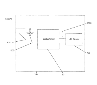
As shown in Figure 10, the LOX device 701 can also produce an effect similar
to a
Stirling engine. The LOX Stirling engine may be powered by the use of two
temperature sinks,
one relatively hot 1001 and the other relatively cold 1005. The LOX Stirling
engine may drive a
fan 1003 to blow air across the evaporative coils of the LOX system to
increase the rate of
evaporation. The hot sink of the Stirling engine may be ambient temperature,
and the cold sink
may be provided by evaporative tubing nearest the LOX storage 703 and/or the
area proximal to
the LOX storage 703. Once the evaporation process begins, i.e., oxygen begins
flowing, the coil
may reduce in temperature starting a Stirling engine fan. Once the fan starts,
evaporation may
become more efficient, i.e., greater convection across tubing may lead to more
heat for
evaporation. No electrical power may be needed to run this system.
The LOX device output may be of higher pressure and higher flow rate than
standard
LOX devices to meet the needs of a critical care jet ventilator. The output
pressure may
typically be approximately 15-80 psi during ventilation mode, and preferably
approximately 25-
40 psi. A flow rate may typically be approximately 4-20 1pm during ventilation
mode, and
preferably approximately 8-10 1pm.
While the foregoing descriptions describe the LOX device being used for an
ambulatory
ventilation therapy, the same principles of the invention can be employed for
stationary
ventilation. For example, a stationary LOX system can be modified with the
embodiments of the
invention to be used to power a mechanical ventilator.
CA 02807416 2013-02-01
WO 2012/024342 PCT/US2011/047994
Optionally, high frequency low volume ventilation can be delivered by the
ventilator and
patient interface where very low volumes of gas are delivered at very fast
frequencies, such as
approximately 5-50 ml at approximately 12-120 cycles per minute, or preferably
approximately
10-20 ml at approximately 30-60 cycles per minute. In this manner, substantial
minute volumes
can be delivered to the lung while controlling the pressures achieved in the
airway and lung more
closely to a desired level, albeit in an open airway system. This delivery
waveform can be
continuous or can be synchronized with an inspiratory phase of breathing.
Again, different
waveforms described can be combined in whole or in part, for example, volumes
can be
synchronized and delivered in one shot during inspiration, and then high
frequency low volume
ventilation can be delivered during exhalation. It should also be noted that
ventilation gas
delivery, when activated, can gradually ramp up so that it is not a sudden
increase in amplitude,
which could arouse the patient.
While the foregoing has described the therapy of this invention using a nasal
interface,
other interfaces may also be included in the invention such as a trans-oral
interface. The tip of a
catheter can be proximal to the mouth entrance, coplanar with the mouth
entrance, or recessed
inside the mouth between the lips and the jaw line. The catheter can be shaped
to be routed
along the teeth, either on the buccal side or lingual side of the teeth, or
through the center of the
mouth. The catheter can be positioned so that a portion of the catheter rests
on the superior
surface of the tongue, or can be positioned so that a portion of the catheter
rests against the
inferior surface of the hard palate, in which case the distal tip of the
catheter may be angled or
curved inferiorly away from the palate and towards the oropharyngeal airway.
The catheter can
be bifurcated so that there is a left and right catheter positioned on both
the right and left side of
the mouth. The catheter can be integral to a bite block or mouth guard. The
catheter preferably
21
CA 02807416 2013-02-01
WO 2012/024342 PCT/US2011/047994
is easily inserted and removed from the patient's mouth. All of the
appropriate details described
previously in conjunction with the nasal interface may apply to the oral
catheter used in
embodiments of the invention.
The present invention can also be used with an endotracheal tube (ET)
interface. This
version of the interface can be helpful to institutions that walk their
patients during the weaning
stages off of invasive mechanical ventilation. Walking patients that are on
ICU ventilators is
typically very onerous because the patient must have the assistance of a
number of medical staff
to move the large and complex ICU ventilator alongside the patient. The
present invention may
be used to help a patient walk, while receiving adequate ventilatory support
from the ventilation
system and interface described in this invention. In this embodiment, the ET
tube connector may
include an attachment for the ventilation interface of this invention. The
patient can breathe
ambient air spontaneously through the proximal end of the ET tube proximal
connector, which is
left open, while the patient's spontaneous breaths are efficaciously augmented
by the ventilation
system and catheter interface of the invention. Optionally, if it is desired
to apply positive end-
expiratory pressure (PEEP), a special PEEP valve may be included for
attachment to the end of
the ET tube. The special PEEP valve may include a one way valve so that
ambient air may be
easily entrained into the ET tube toward the patient's lung by a jet nozzle of
the invention, but
also allows exhalation through the PEEP valve, while maintaining the desired
PEEP level.
Preferably, the patient can still also breathe room air spontaneously through
the PEEP valve
through an inspiratory valve integral to or in parallel with the PEEP valve.
The ventilator used in
the present invention can provide PEEP as previously described by delivering
gas with the
appropriate waveform during the patient's expiratory phase. The catheter tip
can be slightly
proximal to the proximal end opening of the ET tube proximal connector, or can
be coplanar
22
CA 02807416 2013-02-01
WO 2012/024342 PCT/US2011/047994
with the proximal end opening, or can be inserted into the ET tube to the
appropriate depth,
typically at around the mid-point, but the appropriate depth may depend on
other variables of the
system. The depth can be adjustable to optimize the entrainment and
performance or function
for individual situations, as required clinically or for patient tolerance.
The ET tube connector
used in this embodiment of the invention may provide the necessary jet pump
geometry as
previously described in conjunction with the nasal cannula outer concentric
tube. The ET tube
connector can include a jet inlet, jet throat and diffuser section. Or,
alternatively, the ET tube
can be of a special configuration, which incorporates dimensions and
geometries advantageous
to the jet pump performance. All of the appropriate details described
previously with the nasal
interface, apply to the ET tube catheter interface used in this version of the
invention. In
addition, PEEP can be included in the other patient interfaces described in
the invention by
including a similar special PEEP valve for each of the different patient
interfaces.
As previously indicated, Figure 1 is a block diagram describing an embodiment
of the
invention with expanded features and capabilities. A ventilator module
includes or is in
communication with several other accessories or functional modules.
A transmitter and/or receiver 103 may be included to transmit and/or receive
information
regarding the patient, the patient's therapy, and the ventilator performance
to a remote location
for review, analysis and archival. For example, the patient's compliance to
the therapy or
utilization of the therapy can be monitored and assessed. Important
information can be trended,
for example the patient's breath rate, I:E ratio or depth of breathing. Also,
information can be
sent to the ventilator, for example programming of settings to titrate the
ventilator output to meet
the needs of the patient.
23
CA 02807416 2013-02-01
WO 2012/024342 PCT/US2011/047994
An internal or external humidifier 105 can be included for extended uses of
the therapy,
or if using in dry climates. The humidity can be delivered using a
humidification generator that
is integral or coupled with the ventilator, or using a stand alone humidifier.
The humidified air
or oxygen can be delivered through the gas delivery channel of the gas
delivery circuit, or
through another lumen in the gas delivery circuit as previously described, or
through a separate
cannula or tubing. For extended use, when the patient is likely to be
stationary, the
humidification system can be a stationary system and capable of delivering a
relative high
amount of humidity, and for periods of mobility, the patient can either not
receive
humidification, or use a portable humidification system that is capable of
delivering relatively a
small amount of humidity, due to size and energy consumption constraints.
In addition to a LOX system 107, a compressed air source 109 can be included,
typically
external attached to the ventilator, however optionally internal to the
ventilator if the therapy is
being used for stationary use, for example in the home. Examples of a
compressed air source
109 may include a pressurized air source and/or a generator. A blender 111 can
be included to
control the fractional delivered oxygen in a gas delivery circuit 113. The
blender 111 may
receive input from the compressed air source 109 and/or the LOX system 107 and
output to a
ventilator 115. The blender 111 may be used to titrate the amount of oxygen
needed, either
based on a clinical determination, or by pulse oximetry or other biofeedback
signals. For oxygen
concentrations needed that are less than 100%, the system can use compressed
air from a
compressor, tank or wall source, or the air can be entrained into the system
from the pressurized
oxygen gas, for example at the patient interface, or elsewhere in the system,
such as the gas
delivery circuit or ventilator. If air is entrained in, it can be entrained in
from room air. For
treating other diseases and applications, other therapeutic gases can also be
delivered by blending
24
CA 02807416 2013-02-01
WO 2012/024342 PCT/US2011/047994
into the delivered gas, such as helium-oxygen mixtures, nitric oxide, or
combinations of air,
oxygen, helium and nitric oxide. A pulse oximeter 117 can be used to determine
correct blender
settings to achieve proper oxygen saturation. The pulse oximeter 117 can also
be used to titrate
other settings of the ventilator system to meet the physiological needs of the
patient, or to control
the rapid gas conversion mode of a LOX system used with a nasal cannula
instead of a ventilator.
A controller may use a signal from one or more pulse oximeters to switch modes
of the LOX
system. In addition to compressed supplies of oxygen and air gas, the
ventilator can include
internal or external air and oxygen generating means, such as a pump or blower
to create
pressurized air, and an oxygen generator and/or pump to create pressurized
oxygen gas. The
oxygen source can also be liquid oxygen, or a liquid oxygen generating system.
Because the therapy is frequently used to help activities of daily living, and
to promote
activity, a pedometer 119 and/or actigraphy sensor 121 can be included
internal to or external to
the ventilator system. A carbon dioxide monitor 131 may also be included.
An external respiration sensor 123 can be included, such as a respiratory
muscle effort
sensor, a chest impedance sensor, or other types of respiration, such as a
tracheal microphone or
vibration sensor. The external sensor 123 may be used either as a redundant
sensor to a nasal
airflow or nasal pressure sensor 125, or to complement the information
obtained from the nasal
airflow sensor, or in place of the nasal airflow sensor. The nasal airflow or
nasal pressure sensor
125 may measure spontaneous respiration. The nasal airflow or nasal pressure
sensor may be
located at a non-invasive open nasal ventilation interface 129 or at other
appropriate locations.
A drug delivery module 127 can be incorporated internally or externally to the
ventilator
system. Due to challenges with current aerosolized drug delivery inhalers, the
current invention
can be used to propel and deposit medication particles deep in the respiratory
system, without a
CA 02807416 2013-02-01
WO 2012/024342 PCT/US2011/047994
carrier propellant. Because a patient's using the therapy often also requires
prescription
medication, this may be a convenient and efficient way to administer the
medication.
When the therapy is being used for respiratory support, the user may have two
options;
(1) wearing or toting the ventilator so that the user can be ambulatory or
enjoy the activities of
daily living, or (2) stationary use, in the event the patient plans on being
stationary or does not
have the ability to ambulate. The delivery circuit can optionally be provided
in a 25-100 foot
length, such that the gas source and ventilator can be stationary in the
patient's home, while the
patient can move around their home while wearing the interface and receiving
the therapy. Or,
the gas source can be stationary, and connected to the ventilator with a 25-
100 foot hose, so that
the patient can wear or tote the ventilator and be mobile within the range of
the hose. In certain
embodiments, the gas delivery circuit may be connected to a blender, which
receives pressurized
oxygen and pressurized air from, for example, the hospital pressurized gas
supply. In these
applications, in which mobility may be less important, the system can be
attached to the house
gas supply, and higher levels of therapy can be delivered, as well as PEEP
therapy during
exhalation. All of these different options of stationary use and mobile use
apply to the various
different interface techniques described in the foregoing.
The ventilator can be self-contained with a battery and gas supply to enable
it to be borne
by the patient, so that the patient can ambulate and participate in activities
of daily living, which
is made possible by the respiratory support they are receiving from the
ventilator, but in a
package that can easily be borne.
For the therapy described in this invention to be more effectively titrated to
the needs of
the patient, the ventilator system can perform a determination to determine
the level of
respiratory support needed. To accomplish this, the ventilator can titrate the
output to the needs
26
CA 02807416 2013-02-01
WO 2012/024342 PCT/US2011/047994
of the patient, for example, during ambulation or activity the output can
increase. Alternatively,
during higher respiratory rates as measured by the spontaneous breath sensor,
the output can
increase. Or during higher breath effort as measured by the breath sensor, the
output can
increase. Other biofeedback signals can be used. In addition to the output
increasing or
changing to meet the respiratory needs of the patient, the timing of the
ventilator output relative
to the patient's spontaneous inspiratory phase, and the output waveform can
change to meet the
comfort and physiological needs of the patient. For example, during exercise,
the output can
change from an early delivery at 75 ml with an ascending waveform, to being
triggered with a
delay to start for example 100 msec after the start of inspiration, and with a
decelerating
waveform.
To facilitate integration of this new therapy into the existing therapeutic
paradigms, a
convertible system may be provided. Specifically, the patient interface can be
modular, such that
a patient can be administered conventional oxygen therapy with a typical or
slightly modified
oxygen nasal cannula. Then, when it is desired to switch the patient to this
new therapy, an
additional component, such as an outer concentric tube, may be added to the
nasal cannula to
create the jet pump design and to position the distal tips of the cannula
properly to achieve the
function of this invention. Alternatively, for example, a switch on the gas
delivery equipment
can be switched to change the output of the equipment from oxygen therapy, to
this therapy, by
for example, enabling additional breath sensing functions, timing functions,
waveform functions,
and switching to the output amplitude necessary. The LOX portions of the
system can be
modular as well, for example, they can be replaced with oxygen gas cylinders,
wall oxygen,
compressed gas, and an oxygen-air blender.
27
CA 02807416 2013-02-01
WO 2012/024342 PCT/US2011/047994
It should be noted that the different embodiments described above can be
combined in a
variety of ways to deliver a unique therapy to a patient and while the
invention has been
described in detail with reference to the preferred embodiments thereof, it
will be apparent to one
skilled in the art that various changes and combinations can be made without
departing for the
present invention. Also, while the invention has been described as a means for
mobile
respiratory support for a patient, it can be appreciated that still within the
scope of this invention,
the embodiments can be appropriately scaled such that the therapy can provide
higher levels of
support for more seriously impaired and perhaps non-ambulatory patients or can
provide
complete or almost complete ventilatory support for non-breathing or
critically compromised
patients, or can provide support in an emergency, field or transport
situation. Also, while the
invention has mostly been described as being administered via a nasal
interface it should be
noted that the ventilation parameters can be administered with a variety of
other airway interface
devices such as ET tubes, tracheostomy tubes, laryngectomy tubes,
cricothyrotomy tubes,
endobronchial catheters, laryngeal mask airways, oropharyngeal airways, nasal
masks, trans-oral
cannula, nasal-gastric tubes, full face masks, etc. And while the ventilation
parameters disclosed
in the embodiments have been mostly specified to be compatible with adult
respiratory
augmentation, it should be noted that with the proper scaling the therapy can
be applied to
pediatric and neonatal patients. Further, while the target disease states have
mostly been
described as respiratory insufficiency and sleep apnea, other breathing, lung
and airway disorders
can be treated by the therapy with the requisite adjustment in ventilation
parameters, for
example, ALS, neuromuscular disease, spinal cord injury, influenza, CF, ARDS,
lung transplant
bridging, and other diseases can be addressed with this therapy, as well as
mass casualty,
pandemic, military, bridge and transport applications. Lastly, while the
invention has been
28
CA 02807416 2013-02-01
WO 2012/024342 PCT/US2011/047994
described as a stand alone therapy, the therapy can be modular, for example a
ventilation system
can be adapted which can switch between invasive or non-invasive or other
closed system
ventilation modes and the non-invasive open ventilation mode described herein.
Or, the therapy
can be used simultaneously in conjunction with other modes of ventilation,
such as during a
conscious sedation medical procedure in which the patient is ventilated with a
conventional
ventilator as a back up means of respiration while the patient receives
ventilation from the mode
described herein.
Although the foregoing description is directed to the preferred embodiments of
the
invention, it is noted that other variations and modifications will be
apparent to those skilled in
the art, and may be made departing from the spirit or scope of the invention.
Moreover, features
described in connection with one embodiment of the invention may be used in
conjunction with
other embodiments, even if not explicitly stated above. The present invention
may be embodied
in other specific forms without departing from its spirit or essential
characteristics. The
described embodiments are to be considered in all respects only as
illustrative and not restrictive.
29