Note : Les descriptions sont présentées dans la langue officielle dans laquelle elles ont été soumises.
81770720
WIRELESS FETAL MONITORING SYSTEM
Priority_Claim
(00011 This is an international filing of U.S. Patent Application Serial
No. 13/290,002, filed
November 4, 2011, which application claims priority to and the benefit of U.S.
Provisional
Application No. 61/410,803, filed November 5, 2010, entitled "Wireless Fetal
Monitoring
System" (Ref. 921,355-007), U.S. Provisional Application No. 61/410,793, filed
November 5,
2010, entitled "Electronic Data Capture, Documentation, and Clinical Decision
Support System"
(Ref. 921,355:006), U.S. Provisional Application No. 61/454,896, filed March
21, 2011, entitled
"Prenatal Wireless Mobile Pack" (Ref. 921,355-023), and U.S. Provisional
Application No.
61/488,334, filed May 20, 2011, entitled "Low-Cost Portable Fetal Monitor With
Provisions for
Multiple Births" (Ref. 921,355-024).
Statement of Related Applications
100021 This application is related to U.S. Published Patent Application
2011/0137209, Serial
No. 12/917,848, filed November 2, 2010, entitled "Microphone Arrays for
Listening to Internal
Organs of the Body" (Ref. 921,355-004), U.S. Patent Application Serial No.
13/094,678, filed
April 26, 2011, entitled "Ultrasound Patch" (Ref. 921,355-012), U.S. Patent
Application Serial
No. 61/410,793, filed November 5, 2010, entitled "Electronic Data Capture,
Documentation and
Clinical Decision Support System" (Ref. 921,355-006), and US. Patent
Application Serial No.
13/102,817, filed May 6, 2011, entitled "Multipurpose, Modular Platform for
Mobile Medical
Instrumentation" (Ref. 921,355-019).
Field of the Invention
(00031 The present invention relates to fetal and maternal monitoring systems,
particularly
those to monitor for fetal distress. More particularly, the systems, devices,
apparatus and
1
CA 2 8 1 6 8 9 4 2 0 1 8 ¨0 2 ¨2 7
CA 02816894 2013-05-02
WO 2012/061827
PCT/1JS2011/059630
methods relate to improved monitoring systems with enhanced functionality for
wireless fetal
monitoring systems.
Background of the Invention
10004] Fetal Distress Syndrome is an abnormal condition during gestation or
at the time of
delivery, marked by altered heart rate or rhythm and leading to compromised
blood flow or
changes in blood chemistry. Detection of fetal distress syndrome is done in
obstetrics by
Cardiotocography, the simultaneous measurement of fetal heart rate and uterine
contractions.
The change in fetal heart rate as a response to uterine contractions is the
diagnostic basis of fetal
distress syndrome. See, e.g., "Cardiotocography", van Geijn, H.P., Textbook of
Perinatal
Medicine, Parthenon Publishing, 1998, Vol. 2, p. 1424-8. In every-day
obstetrics practice,
physicians routinely prescribe cardiotocograms to detect fetal distress
syndrome.
100051 Cardiotocography, or electronic fetal monitoring (EFM), is a common
non-invasive
diagnostic technique utilized in obstetrics to detect and determine the extent
of Fetal Distress
Syndrome. Cardiotocography uses the simultaneous measurement of the fetal
heart rate
("cardio") and the uterine contractions ("toco") to detect any abnormalities.
[0006] Current technology is composed of a central unit, which contains a
printer, a Doppler
fetal monitor (to register the fetal heart rate), and a tocodynamometer (to
register uterine
contractions). In currently used equipment, the sensors are affixed to the
abdomen of the mother
and connected to the central unit via connecting cables.
100071 Typically, a conventional tocodynamometer is a strain gauge attached
to a belt around
the abdomen of the patient. The strain gauge detects the tension on the uterus
wall during
contractions. Also conventionally, a Doppler ultrasound transducer measures
fetal heart rate.
The result is a graphical overlay of both measurements, seen either on a
screen or on paper. By
comparing changes in fetal heart rate to maternal contractions, the healthcare
provider assesses
the status of the fetus and determines if fetal distress is present.
[0008] Currently, obstetric patients requiring EFM are referred to either a
hospital or
outpatient clinic setting where monitoring takes place under the physical
presence of a technician
or nurse. While resting in bed, the sensors are placed on the patient and the
sensors are
connected to a measuring apparatus with cables, thus limiting the patient's
mobility. The
measuring apparatus displays two simultaneous graphs, one with the fetal heart
rate and the other
2
CA 02816894 2013-05-02
WO 2012/061827 PCT/US2011/059630
with the uterine contractions (on paper or screen). The practitioner
determines the presence and
the severity of Fetal Distress Syndrome based on these two graphs. See, e.g.,
"Interpretation of
the Electronic Fetal Heart Rate During Labor", American Academy of Family
Physicians (1999).
10009]
Traditional fetal monitoring systems include are relatively bulky, expensive
and
intended to be used in designated centers (e.g., hospitals/physicians or
offices). This
arrangement raises several issues.
[0010]
First, there exists a limited accessibility to fetal monitoring. Currently, in
United
States, pregnant mothers must commute to either a physician's office or a
designated fetal
monitoring center and these centers are often difficult for patients to
access. This means that the
pregnant mother should take a trip to the hospital for a monitoring session
which puts the burden
of time and expense both on the mother and accompanying person(s) as well as
the healthcare
system. Therefore, with traditional systems monitoring of pregnant mothers,
who are not
categorized as high risk, is limited to a few times during course of
pregnancy. For example,
typical testing is on the order of 2 times every week during the last
trimester. This leads
potentially to reduced efficacy of monitoring in terms of missing critical
incidents. Immobility
of the traditional system also means that pregnant mothers in remote areas
and/or in the
underserved areas with limited access to the healthcare system (e.g., in the
case of many
developing countries) are not being tested at all.
[0011]
Second, there is limited mobility of the patient during fetal monitoring.
Pregnant
mothers who undergo fetal monitoring require a minimum of 45 minutes and up to
4 hours for
each monitoring session. During this time the patient must remain in a relaxed
position (usually
recumbent) connected to the recording device. Putting on and adjusting the
position of fetal
monitoring system sensors takes substantial amount of time (i.e., on the order
of 10-20 minutes).
Using the traditional wired fetal monitoring system, in case that the patient
needs to move during
the test (e.g. goes to bathroom or the like) the setup needs to be removed and
placed back
afterwards. This adds additional time and cost burden in the hospitals.
100121
Third, there is a lack of remote accessibility to data for evaluation.
Currently most
cardiotographic devices do not have the capability of digital storage and
transfer. The usual
manner in which a fetal monitoring study occurs involves a paper tracing that
is carried to the
health care provider or Physician for interpretation, and then stored in the
patient's medical
3
CA 02816894 2013-05-02
WO 2012/061827 PCT/US2011/059630
record. Often the length of these strips exceeds the capacity for storage for
clinical, private
physician practices and even hospital systems.
Additionally, the lack of digital data
transferability means that interpreting the data is possible in only places
that trained care
providers (i.e. nurses or physicians) are accessible.
=
[0013]
Doppler ultrasound is a non-invasive monitoring approach to extract
information
about moving structures inside the body. It can be used for diagnosis of many
cardiovascular
conditions as well as in fetal health monitoring. Current ultrasonic
technologies rely on bedside
monitoring that is limited to the hospital and clinical settings. A major
obstacle in transforming
the traditional ultrasonic technologies into the emerging wireless health
solutions is the
significantly high computational complexity of the algorithms that process the
plethora of the
Doppler shifted data acquired from ultrasound transducers.
[0014]
With the growing interest in wireless health technologies and their potential
applications, efficient design and development of wearable medical devices is
becoming
unprecedentedly important to researchers in both academia and industry. See,
e.g., R. Jafari, S.
Ghiasi, and M. Sarrafzadeh, "Medical Embedded Systems," in Embedded System
Design:
Topics, Techniques and Trends, ser. IFIP Advances in Information and
Communication
Technology, A. Rettberg, M. ZaneIla, R. Domer, A. Gerstlauer, and F. Rammig,
Eds. Springer
Boston, 2007, vol. 231, pp. 441-444. The main driving factors in designing
this new generation
of the health paradigm include cost, power consumption, and wearablility, with
power
consumption being the center of many research efforts due to its dramatic
influence on other
design objectives. See, e.g., C. Park, P. Chou, Y. Bai, R. Matthews, and A.
Hibbs, "An Ultra-
wearable, Wireless, Low Power ECG Monitoring System," in Biomedical Circuits
and Systems
Conference, 2006. BioCAS 2006. IEEE, December 2006, pp. 241-244; P. Zappi, C.
Lombriser, T.
Stiefmeier, E. FareIla, D. Roggen, L. Benini, and G. Troster, "Activity
Recognition From On-
Body Sensors: Accuracy-Power Trade-off By Dynamic Sensor Selection," Lecture
Notes in
Computer Science, vol. 4913, p. 17, 2008; V. Leonov, P. Fiorini, S. Sedky, T.
Torfs, and C. Van
Hoof, "Thermoelectric Mems Generators as a Power Supply for a Body Area
Network," vol. 1,
June 2005, pp. 291-294; S. Xiao, A. Dhamdhere, V. Sivaraman, and A. Burdett,
"Transmission
Power Control in Body Area Sensor Networks for Healthcare Monitoring," IEEE
Journal on
Selected Areas in Communications, vol. 27, no. 1, pp. 37-48, 2009; and H.
Ghasemzadeh and R.
4
CA 02816894 2013-05-02
WO 2012/061827 PCT/US2011/059630
Jafari, "A Greedy Buffer Allocation Algorithm for Power-Aware Communication in
Body
Sensor Networks," in Proceedings of the eighth IEEE/ACM/IFIP International
Conference on
Hardware/Software Code.sign and System Synthesis, ser. CODES/ISSS '10. New
York, NY,
USA: ACM, 2010, pp. 195-204.
[0015] An important angle of low-power design is development of efficient
signal processing
and data reduction algorithms that reduce computation load of the processing
units, allowing
low-power low-cost processors to be embedded with the wearable device. While
much work has
been done on designing signal processing algorithms for a variety of sensing
modalities such as
motion sensors (H. Ghasemzadeh, V. Loseu, and R. Jafari, "Structural Action
Recognition in
Body Sensor Networks: Distributed Classification Based on String Matching,"
IEEE
Transactions on Information Technology in Biomedicine, vol. 14, no. 2, pp. 425-
435, 2010; A.
Barth, M. Hanson, H. Powell, and J. Lach, "Tempo 3.1: A Body Area Sensor
Network Platform
for Continuous Movement Assessment," in Wearable and Implantable Body Sensor
Networks',
2009, BSN 2009. Sixth International Workshop on, 2009, pp. 71-76.),
Electrocardiography (D.
Jun, X. Miao, Z. Hong-hai, and L. Wei-feng, "Wearable ECG Recognition and
Monitor," in
Computer-Based Medical Systems, 2005. Proceedings. 18th IEEE Symposium on,
June 2005, pp.
413-418; M. Ayat, K. Assaleh, and H. Al-Nashash, "Prototype of a Standalone
Fetal ECG
Monitor," in Industrial Electronics Applications (ISIEA), 2010 IEEE Symposium
on, 2010, pp.
617-622), and photo-plethysmogram sensors (J. Espina, T. Falck, J. Muehlsteff,
and X. Aubert,
"Wireless Body Sensor Network for Continuous Cuff-less Blood Pressure
Monitoring," in
Medical Devices and Biosensors, 2006. 3rd IEEE/EMBS International Summer
School on, 2006,
pp. 11-15), ultrasonic signal processing for stringent constrained computing
platforms has not
been studied in the past.
[0016] Traditional ultrasound technologies have been used in a variety of
application domains
such as ultrasound imaging (E. J. Gussenhoven, C. E. Essed, C. T. Lancee, F.
Mastik, P.
Frietman, F. C. van Egmond, J. Reiber, H. Bosch, H. van Urk, J. Roelandt, and
N. Born,
"Arterial Wall Characteristics Deteiiiiined by Intravascular Ultrasound
Imaging: An in vitro
Study," Journal of the American College of Cardiology, vol. 14, no. 4, pp. 947-
952, 1989, ACC
Anniversary Seminar) to produce pictures of the inside of the body, blood flow
monitoring (A.
Azhim, J. Yamaguchi, Y. Hirao, Y. Kinouchi, H. Yamaguchi, K. Yoshizaki, S.
Ito, and M.
CA 02816894 2013-05-02
WO 2012/061827 PCT/US2011/059630
Nomura, "Monitoring Carotid Blood Flow and ECG for Cardiovascular Disease in
Elder
Subjects," in Engineering in Medicine and Biology Society, 2005. IEEE-EMBS
2005. 27th
Annual International Conference of the, 2005, pp. 5495-5498) to measure
velocity of blood flow
in different arteries for use in monitoring cardiovascular diseases, and
Cardiotocography (C.-Y.
Chen, J.-C. Chen, C. Yu, and C.-W. Lin, "A Comparative Study of a New
Cardiotocography
Analysis Program," in Engineering in Medicine and Biology Society, 2009. EMBC
2009. Annual
International Conference of the IEEE, Sept. 2009, pp. 2567-2570) to measure
fetal heart rate and
assess the effect of uterine contractions on fetal heart rate. However, the
main challenge in
transition from traditional ultrasound technologies to wearable platforms is
the demand for a
very high computational power. Compared to the other sensing modalities,
ultrasound signals
require a relatively high sampling frequency, producing large volumes of data
that need to be
processed. For instance, in a blood flow monitoring application, relevant
infoiniation may
appear in the frequency band of 100-4200 Hz, which may require a sampling
frequency of 10
kHz as used in Azhim, et al, above. Moreover, a minimum sampling rate of 1600
Hz for
capturing fetal movements is suggested in C.-Y. Chen, J.-C. Chen, C. Yu, and
C.-W. Lin, "A
Comparative Study of a New Cardiotocography Analysis Program," in Engineering
in Medicine
and Biology Society, 2009. EMBC 2009. Annual International Conference of the
IEEE, Sept.
2009, pp. 2567-2570. The large volume of sampled ultrasonic signals needs to
undergo fast
signal conditioning algorithms in order to extract relevant information in
real-time.
[00171 As to patents, Rapoport, U.S. Patent No. 5,257,627, discloses a
portable apparatus for
the non-invasive, simultaneous, self-testing of fetal and maternal signals. It
includes a user
display to indicate that the device is operational, an ultrasonic system to
detect fetal heart rate
connected to said device, a detection system for maternal input signal
connected to said device,
wherein the device has signal processor for simultaneously processing fetal
heart rate and
maternal input signals, and also has a communication linking means for the
simultaneous
transmission of fetal heart rate and maternal input data to a remote output
device.
10018] Lewis et al., U.S. Patent No. 6,115,624, discloses an intrauterine
catheter device for
monitoring fetal and/or maternal heart rate, including an elongate housing
having proximal and
distal portions, an array of ECG electrodes on the distal portion and one or
more acoustic or
other mechanical sensors on the distal portion. A pressure transducer may also
be provided on
6
CA 02816894 2013-05-02
WO 2012/061827 PCT/US2011/059630
the distal portion. Processor circuitry compares the ECG signal with the
output signal of the
acoustic sensor to derive fetal and/or maternal heart rate. An intrauterine
catheter device is also
provided, including a reference electrode on its distal portion, and an array
of active electrodes
spaced apart from one another on the distal portion. The device may also
include a pressure
transducer on the distal portion and processor circuitry coupled to the array
of active electrodes
and/or to the reference electrode for deriving fetal ECG from signals produced
by the array of
active electrodes. Alternatively, the array of electrodes and acoustic sensors
may be provided on
a flexible pad that may be secured to the abdomen of a pregnant mother. An
intrauterine catheter
device is also provided, including a plurality of lumens communicating with a
differential
pressure transducer provided on its distal portion, and having a zeroing
switch on its proximal
portion for resetting the pressure transducer in situ.
100191 Powell et al., U.S. Patent Application No. 2006/0149597, makes the
following
statements in the patent. It is said to provide a data processing tool for the
viewing of real-time,
critical patient data on remote and/or mobile devices. It is said that the
tool renders graphical
data on the screen of the remote device in a manner that makes it practical
for the health care
provider to accurately and timely review the data for the purpose of making an
informed decision
about the condition of the patient. Charting control is established and
implemented using the
latest GDI+, GAPI and PDA drawing techniques. The charting components provide
landscape
support, an ability to overlay patient data and patient images, zoom in/zoom
out, custom variable
speed scrolling, split screen support, and formatting control. It is said that
the methodology
operates as an asynchronous application, without sacrificing processing time
in the
mobile/handheld device. The methodology allows the critical patient data to be
streamed in real-
time to the handheld device while conserving enough CPU power to
simultaneously allow the
end user to interact at will with the responsive display application. The
methodology is
structured using object oriented concepts and design patterns. Each logical
tier of the
methodology, from the data access objects and the charting control objects, to
the user interface
objects, is structured with precise interfaces. The methodology implements an
IT management
console that allows system managers to monitor the exchange of data between
hospital systems
and the primary database, including all patient data packets, notifications
and alerts, connected
remote devices.
7
CA 02816894 2013-05-02
WO 2012/061827 PCT/US2011/059630
[0020]
Hayes-Gill et al., U.S. Patent No. 7,532,923, it discloses apparatus for
detecting the
heart rate of a fetus. The apparatus includes at least two detectors for
detecting heart beats of the
fetus, each detector comprising at least two electrodes for detecting ECG
signals. A processor,
which is coupled to the detectors, is used to process the ECG signals received
from each detector
and determine the heart rate of the fetus.
[0021]
James et al., U.S. Patent Application No. 2007/0213672 discloses a monitor for
fetal
behavior by receiving ECG data from a set of electrodes attached to a material
body. A
waveform pre-processor identifies a succession of fetal ECG complex waveforms
within the
received data and a waveform processor determines differences in the processor
succession of
fetal ECG complex waveforms over time. An event logger determines from the
determined
differences a number of fetal movements during the period of time. Fetal
spatial presentation
and/or position within the uterus may also be determined from fetal ECG data
acquired from a
plurality of electrodes positioned on the maternal abdomen in a predetermined
configuration. A
number of fetal ECG complex waveforms are identified within the data, and each
of the
waveforms is compared with a set of predetermined fetal ECG complex templates
ascribed to the
predetermined electrode configuration to determine a template that best
matches the identified
fetal ECG waveforms.
[0022]
Hayes-Gill et al., WO 2001/004147, it discloses a system for detecting uterine
activity
uses cutaneous electrodes on the maternal abdomen to obtain
electrophysiological signals that
can be used to obtain fetal and maternal heart rate. The apparatus includes a
first input for
receiving electrical signals from the cutaneous electrodes and a second input
for receiving
movement signals indicative of a movement of the maternal body from a movement
detector. A
signal processor separates a uterine electromyogram signal from fetal and
maternal heart rate
signals and filters out motion artifacts from the electromyogram using the
movement signals. An
output presents electrohysterogram (EHG) data from the uterine electromyogram
signal.
[0023] Against this background is a compelling need to both bring
healthcare to the
underserved population, as well as to deliver more effective and cost
effective healthcare.
Further, there is a need to provide a marriage of wireless technologies in a
way that are both safe
and effective. Despite these compelling needs, the difficulty in detecting
Fetal Distress
Syndrome remains.
8
CA 02816894 2013-05-02
WO 2012/061827 PCT/US2011/059630
Summary of the Invention
[0024] A wireless
mobile wearable device is used to monitor the pregnant women uterine
contractions and fetal heartbeat simultaneously. The device consists of a
sensing component and
a gateway for wireless communication with the data network. The instant
wireless fetal
monitoring system takes standard fetal monitoring technology augmented with
wireless
technology, to enable a new location independent paradigm of care. This device
is used by a
clinician or a skilled technician to monitor the patient (e.g., at a local
clinic) while the diagnosis
is performed by the clinician who is remote from the patient. Thus the device
provides clinical
expertise remotely, greatly benefiting patients especially in geographical
regions that
traditionally experience high rates of unattended pregnancies and poor fetal
and maternal
outcomes due to inadequate ante-partum care.
[0025] A wireless
fetal and maternal monitoring system includes a fetal sensor unit adapted to
receive signals indicative of a fetal heartbeat, or multiple fetal heartbeats
in the case of multiple
fetus, the sensor optionally utilizing a Doppler ultrasound sensor. A short-
range transmission
unit sends the signals indicative of fetal heartbeat to a gateway unit, either
directly or via an
auxiliary communications unit, in which case the electrical coupling between
the short-range
transmission unit and the auxiliary communications unit is via a wired
connection. The short-
range transmission unit is a low power transmission unit, preferably having
specific absorption
rate (SAR) of less than or equal to 0.1 watts/kg, and more preferably less
than 0.05 watts/kg, and
most preferably less than or equal to 0.01 watts/kg. The system includes a
contraction actuator
actuatable upon a maternal uterine contraction, which optionally is a EMG
sensor. A gateway
device provides for data visualization and data securitization. The gateway
device provides for
remote transmission of information through a data communication network. A
server adapted to
receive the information from the gateway device serves to store and process
the data, and an
interface system to permits remote patient monitoring.
[0026] The
sensing component of the device includes sensors and short-range wireless
interface and is worn by pregnant mother. The fetal heartbeat is detected
using either ultrasound
Doppler (detecting movement of fetus heart), sound microphones (detecting
sound of fetus heart)
9
CA 02816894 2013-05-02
WO 2012/061827 PCT/US2011/059630
or ECG sensors (detecting ECG of fetus heart). Contraction is measured either
by a pressure
sensor, EMG of uterine muscles or manually entered by user. The resulting
signals are
processed and transmitted out to the gateway, using short range wireless
interface or a wired
connection.
[0027] The data is visualized in the gateway for local monitoring then it
is security encoded
and sent out to a secure server using wireless internet connectivity (Wi-Fi,
GPRS, Edge, 3G or
the like) on the gateway. The contraction and heartbeat data are optionally
reviewed by
authorized users (care provider, relatives, or the like) over internet using a
web access.
[0028] In yet another aspect of these inventions, signal processing and
data reduction
algorithms are provided which are computationally simple and enable real-time
monitoring on
lightweight embedded processors. In particular, algorithms that can
efficiently measure fetal
heart rate from Doppler shifted signals are used. An autocorrelation-based
approach locates
repeating patterns in the signal. An envelope detection technique is used to
reduce the sampling
rate in early stages of the processing, leaving only useful information for
the more intensive
computations in the autocorrelation stage. The algorithms are implemented and
their
effectiveness is demonstrated using a custom-designed hardware platform that
is specifically
designed for monitoring fetal heart rates.
[0029] In an effort to investigate efficient signal processing techniques
for the ultrasound
signals with a high computational demand, a signal processing model transforms
sensor readings
into useful information while reducing the amount of data passed through the
processing chain as
early as possible in the processing chain. While the inventions can be used in
many application
domains, the focus of the embodiments are fetal heart rate monitoring and an
application where
the algorithms are used for Cardiotocography.
[0030] In yet another aspect of these inventions, a wireless prenatal
monitoring kit takes a
unique wireless fetal/maternal monitoring device and combines with wireless
biomarker devices
into, preferably, a single kit which allows remote prenatal monitoring of high
risk pregnant
patients anywhere cell service or Wi-Fi is available. The wireless prenatal
monitoring system is
a unique pregnancy monitoring kit that combines wireless biomarker devices for
monitoring fetal
and maternal health information during the all phases, but particularly later,
phases of pregnancy.
[0031] The wireless prenatal monitoring hub is a plug-in hub that
optionally directly stores
81770720
the data point at every time interval that the patient is monitored. The hub
is used as a separate
trending device to display the information for the mother throughout the day,
month and
throughout the pregnancy.
[0032] In the preferred embodiment, the wireless prenatal monitoring kit
preferably
contains the following: a wireless fetal maternal monitoring device, a
wireless blood pressure
device, a wireless glucometer, a urine reagent dip sticks, and a wireless
communication
device. The wireless communication device optionally may be a cell phone
gateway or
wireless hub.
[0033] The wireless prenatal monitoring kit is not limited to the specified
devices. The
prenatal monitoring kit can also include a pulse oxymeter or wireless weight
scale. Any
monitoring devices that are wireless, e.g., Bluetooth driven, may be adapted
for use in
conjunction with the kit and system herein.
[0034] Accordingly, it is an object of these inventions to provide systems,
methods and kits
which can effectively deliver high quality health care, often remotely and
wirelessly, at low
cost, to provide clinically effective solutions.
[0034a] According to an embodiment, there is provided a wireless fetal and
maternal
monitoring system comprising: a fetal sensor unit adapted to provide signals
indicative of a
fetal heartbeat, a contraction sensor adapted to provide signals indicative of
a maternal uterine
contraction upon a maternal uterine contraction, a digitization and control
unit adapted to
receive the signals indicative of a fetal heart rate and the signals
indicative of a maternal
uterine contraction, the digitization and control unit including a heart rate
calculation system
to calculate the fetal heart rate, a fetal heart rate register for storing the
calculated fetal heart
rate, the fetal heart rate register being refreshed per fetal heartbeat, a
maternal uterine
contraction register to store the signals indicative of maternal uterine
contraction, the
digitization and control unit providing data fusion by transmitting at least
the calculated fetal
heart rate from the fetal heart rate register and data based on the signals
indicative of the
maternal uterine contraction from the maternal uterine contraction register; a
short-range
11
CA 2816894 2018-10-11
= 81770720
transmission unit adapted to receive from the digitization and control unit
the fused data
signals and to retransmit the signals, a microphone comprising a maternal
heartbeat sensor,
and a processor including a comparator and a flag memory to eliminate as an
erroneous
measure a first sensed beat period by comparison to a second sensed beat
period and to set a
flag in the flag memory.
Brief Description of the Drawings
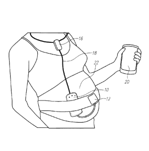
[0035] Fig. 1 is a perspective illustration of system components of the
fetal monitoring
system.
[0036] Fig. 2 is a perspective view of a gateway device displaying a fetal
or maternal
images.
[0037] Fig. 3 is a functional block diagram of the system for fetal and
material monitoring.
[0038] Fig. 4 is a second functional block diagram of the system for fetal
and material
monitoring.
[0039] Fig. 5 is a schematic diagram showing timing of data transmission in
the system.
[0040] Fig. 6 is an illustration of patch for fetal monitoring system.
[0041] Fig. 7 components of the fetal monitoring device: (a) Toco sensor
with belt; (b)
FHR monitor.
[0042] Fig. 8 is plan view illustrating placement of the fetal monitoring
system on the
mother.
[0043] Fig. 9 is a simplified schematic of the FHR user interface.
[0044] Fig. 10 is a connector and cable design for powering: (a)
interconnection between
two components; (b) interconnection between three component.
1 1 a
CA 2816894 2018-10-11
CA 02816894 2013-05-02
WO 2012/061827 PCT/US2011/059630
[0045] Fig. 11 is a typical baseband Doppler signals: (a) analog output
from 100-500 Hz
analog filter with 2400 samples per second ("sps") indicated; (b) output from
digital envelope
detector, before and after down-sampling to 240 sps.
[0046] Fig. 12 is an illustration of the data packet: (a) format; and (b)
timing.
100471 Fig. 13 is a block diagram of the signal processor with timing
generation.
100481 Fig. 14 is an illustration of synchronous communication and sample
timing.
[0049] Fig. 15 shows photographs of system components: (a) assembled FHR
monitor, and
(b) toco sensor.
[0050] Fig. 16 shows a schematic diagram of the digital signal processing
for calculation of
FHP from Doppler ultrasound.
[0051] Fig. 17 shows a sampling spaced in the worst case.
[0052] Fig. 18 shows the required sampling rate versus desired precision
for varying Doppler
frequencies.
[0053] Fig. 19 shows the architecture of the autocorrelation algorithm.
[0054] Fig. 20 shows autocorrelation of a synthesized Doppler signal.
[0055] Fig. 21 is a display of an interface displaying, among others, the
fetal heart rate and
signals corresponding to maternal uterine contractions.
[0056] Fig. 22 is a perspective view of the preferred components of the
prenatal wireless
mobile pack.
[00571 Fig. 23 is a schematic block diagram of the end-to-end solution for
the prenatal
wireless mobile pack.
[0058] Fig. 24 shows test results in an early laboring patient comparing
the subject unit and a
standard cardiotocograph.
Detailed Description of the Invention
[0059] Fig. 1 illustrates one implementation of the wireless fetal
monitoring system based on
this invention. In one implementation, the device uses a fetal heartbeat
detector, such as an
ultrasound Doppler detector, and a pressure sensor, such as a toco transducer,
for monitoring of
contractions. The device consists of a central unit 10 which houses the fetal
heartbeat detector
(ultrasound piezoelectric transducer in one implementation of an ultrasound
Doppler detector),
12
CA 02816894 2013-05-02
WO 2012/061827 PCT/US2011/059630
operating at the frequency in the range of 1-10MHz. The toco transducer 12 may
be integrated
with the sensor or central unit 10, or may be separate and connected to the
central unit using a
wire.
[0060] The
central unit includes a short range communication module. A gateway 20 is used
for local data storage, visualization and to communicate with the mobile data
network to transmit
data to the server. The short range communication is employed for safety
considerations so that
radio frequency (RF) emission with high power (that is required for
communication to the
cellular network) gateway 20 is placed relatively far from the mother/baby 22.
The short range
wireless communication module implemented in the central unit 10 has low power
RF emission
thus it is very less likely to be harmful. The short-range transmission unit
is a low power
transmission unit, preferably having specific absorption rate (SAR) of less
than or equal to 0.1
watts/kg, and more preferably less than 0.05 watts/kg, and most preferably
less than or equal to
0.01 watts/kg. This level of SAR is implemented as known to those skilled in
the art, such as
through the use of Bluetooth technology. Preferably class 3 Bluetooth
technology or otherwise
the lowest radiation class is utilized. Optionally, radiofrequency shielding
is utilized.
100611 One
significant advantage of using a gateway in conjunction with the short range
body
sensor wireless link to the device against direct link from body worn sensor
to mobile data
network is reducing fetus and pregnant mother exposure to the RF radiation of
wireless fetal
monitor.
100621 Both
wireless gateway and Bluetooth module emit non-ionizing radiation at
frequencies ranging in 1-2.5GHz. The FCC limit on the Specific Absorption Rate
(SAR), a
measure of the rate of energy absorption by the body when exposed to an RF
field (see, e.g.,
C.K. Choul, et al, "Radio Frequency Electromagnetic Exposure: Tutorial Review
on
Experimental Dosimetry", Bioelectro-magnetics, Vol. 17, Issue 3, pages 195-208
(1996)), for
cellular telephones is 1.6 W/kg.
100631 The
SAR rate of the gateway is comparable to typical smart phones, in the range of
0.5-1.5 W/kg (see, e.g., Electromagnetic Fields and Public Health: Mobile
Phones", World
Health Organization, Fact Sheet No 193, May 2010) A Bluetooth radio module
configured in
class II generates a SAR level of ¨0.01 W/kg. Therefore, by utilizing a
gateway, placed
relatively far from the pregnant woman the SAR level can be reduced by two
orders-of-
13
CA 02816894 2013-05-02
WO 2012/061827 PCT/US2011/059630
magnitude and well below FCC standards. Using the optional external Bluetooth
necklace,
rather than the built-in module, further diminishes the undesired RF emission
exposure to the
fetus to an even less significant value.
[0064] In order to eliminate any concern regarding absorption of radio
frequency signals by
the fetus, an auxiliary communication unit 16 is optionally utilized. In one
variation, the
auxiliary communication unit is in the form of a necklace, which locates the
transmitter to the
gateway 20 at a significant distance, such as at least two feet (though this
distance will vary
based on the height and physical structure of the mother) from the fetus. In
this implementation,
the communication from the central unit 10 to the auxiliary communication unit
16 may be
wireless, but is preferably wired via connection 18. The wired, i.e., not
wireless, communication
from the central unit 10 minimizes radiation to the fetus.
100651 Fig. 1 illustrates the form factor implementation for the different
components of the
sensing front-end. The central unit integrates the ultrasound transducers,
processing and control
circuitry, and the internal Bluetooth communication module.
[0066] Separate belts are preferably used to hold the central unit and toco
sensor so that
during operation, position of sensors can be independently optimized. The
central unit includes
ultrasound transducers as well as control, processing and Bluetooth
communication circuitry. A
toco pressure sensor, an optional audio feedback earphone and the optional
external Bluetooth
necklace can be plugged in to the central unit.
[0067] Fig. 2 is a plan view of a representative gateway device 20. The
gateway device may
preferably include data visualization. In Fig. 2, the fetal heartbeat is shown
in the upper
waveform, and the signal corresponding to the maternal contractions are
displayed in the lower
portion. Optionally, the display may comprise a touch screen display. The
gateway device
further preferably includes encoding functionality, to permit the secure
transmission of medical
data.
[0068] Fig. 3 shows a schematic functional block diagram of one
implementation of the
system. One possible architecture for the system comprises a wireless sensing
interface, data
transmission gateway, data storage, and user interface over the internet. The
fetal heartbeat
detector, such as a piezoelectric ultrasound transducer 30, is an input to the
sensing hardware 32.
The sensing hardware 32 may be characterized as wireless, though certain
embodiments
14
CA 02816894 2013-05-02
WO 2012/061827 PCT/US2011/059630
contemplate wired connections. The sensing hardware 32 may optionally include
an amplifier,
such as a low noise amplifier (LNA). The output of the sensor 30 is provided
to signal processor
34, such as Doppler signal processing detector, for processing and heartbeat
detection. In turn,
the signal digitization unit 36 digitizes the signal, such as through an
analog to digital converter
(ADC), and may optionally perform heart rate calculation, as well as to
provide control and data
functions. The maternal uterine contraction actuator, such as a toco pressure
sensor 38, provides
output corresponding to maternal contractions to amplification and signal
conditioning circuit 40,
again optionally a utilizing a low noise amplifier (LNA), which in turn is
passed to the signal
digitization unit 36. In one embodiment, an internal short range transmission
unit 42 is provided
which communicates with the gateway 50. Alternately (or in combination) the
external short
range transmission unit 44 communicates, such as by RF communication, with the
gateway 50.
In the later embodiment, preferably a wired communication path 54 is provided.
A
communication network 56, such as the internet or telephone network, couples
the device to a
server 62, preferably a secure data server. A user interface 64 optionally
permits remote patient
monitoring, preferably in a graphical format. The user interface 64 may be
displayed on a
computer or other web-enabled device.
[0069] Fig.
4 shows a schematic functional block diagram of one implementation of the
system. The fetal heart beat 70 is received by the sensor 72, shown in Fig. 4
with the ultrasound
embodiment being a transducer and optional amplifier, most preferably a low
noise amplifier.
The output of the sensor 72 is communicated to the processor 74, preferably
for signal
processing and heartbeat detection. Uterine contraction information 80 is
detected via sensor 82,
shown in this implementation as toco sensor and amplifier 82. Optionally, the
sensor 82 includes
amplification and signal conditioning circuitry. The output of the processor
74 and sensor 82 is
managed by digitization and control block 76. Optionally, the control block 76
includes one or
more of the functions of signal digitization, heart rate calculation systems
or algorithms and data
fusion. The output of block 76 is communicated to gateway 80, which preferably
serves as a
gateway for data storage, display and communications with the network.
Various
communication path options include external short range RF communication path
84, such as
Bluetooth, and internal short range RF communication path 86, such as internal
Bluetooth short
range data communication, and wired communication 88 to the gateway 80. The
wireless
CA 02816894 2013-05-02
WO 2012/061827 PCT/US2011/059630
communication paths are low power communications. The short-range
communications
preferably have specific absorption rate (SAR) of less than or equal to 0.1
watts/kg, and more
preferably less than 0.05 watts/kg, and most preferably less than or equal to
0.01 watts/kg. A
communication network 90, such as the internet, couples the gateway 80 to
storage 90,
preferably secure server based storage, and an optional physician gateway 94
or other user
interface, preferably for security decoding, data visualization and
communication functions.
100701 One
particular implementation of the sensing hardware is described with reference
to
FIGS. 3 and 4. Front-end of the system includes an ultrasound Doppler
heartbeat detector and a
toco pressure sensor, resembling a standard fetal monitoring system. A set of
two half disc
2MHz PZ-27 ultrasound ceramic transducers (Ferroperni, Piezoceramics) along
with off-the-
shelf electronics are employed to detect fetal heartbeat, and to provide an
audio feedback to help
positioning of the ultrasound device during monitoring. A low-cost 8-bit
microcontroller
(PIC16F688, Microchip) is used for system control, analog to digital
conversion via an on-
chipl 0-bit ADC, onboard signal processing and communication with the
Bluetooth module.
[0071] Due
to motion artifacts and/or inappropriate positioning of transducers on a
mothers
abdomen, the heartbeat detector often misses one or more heartbeats. An
algorithm for heartbeat
to heart rate conversion, embedded on microcontroller, eliminates the
erroneous measure via
comparing input beat period with the previously stored value. In case that
current reading is
outside of 25% of the stored value, the algorithm drops the new reading and
raises a flag. If 6
consecutive readings are constantly out of that range the new reading is
stored as updated
measurement result.
[0072] A low-
cost disposable toco sensor (FeatherLiteToco, Ventrex) which consists of a
pressure transducer configured in a Wheatstone bridge is used for contraction
monitoring. An
instrumentation amplifier with a gain of 100 amplifies the signal to the ADC
input range.
Further baseline subtraction and gain adjustment is implemented in the gateway
software. The
device makes an authenticated link with the gateway using a Bluetooth module
(RN-41, Roving
Networks) configured in Serial Port Profile. The module's output RF power can
be programmed
for either class I, II or III. An optional external Bluetooth, in a necklace
form factor is designed
so when it is plugged in to the unit, substitutes the internal Bluetooth.
[0073] Current consumption of the module is dominated by electronics
driving ultrasound
16
CA 02816894 2013-05-02
WO 2012/061827 PCT/US2011/059630
crystals and the Bluetooth module, measured at 60mA and 25mA, respectively
from the 3.3V
regulated supply. The device is powered by two standard AAA batteries which
results in
approximately 8 hours of constant running time. By powering from separate up-
converting
voltage regulators, interference between the sensing interface electronics and
the Bluetooth
module is minimized.
[00741 Fig.
5 depicts various timings for data transmission in the system. The decision as
to
what data to send within the system, and how frequently to send it, strongly
relate to the power
consumption of the system. Internal hardware registers for heart rate and
contraction are being
updated each beat and at a 10Hz rate, respectively. A transmission between the
gateway and the
central unit is initiated by the gateway and acknowledged by a 3 byte response
from the central
unit consisting of the heart rate, contraction information, and an error code
at an update rate of 2-
Hz. Data synchronization in this embodiment occurs at a lower frequency than
above, such as
every 30 seconds. The gateway has been implemented as an application on an
Android based
Smartphone (Nexus One, Google/HTC). It uses internal Bluetooth on the phone to
create the
link with the sensing hardware and chooses the best available data
communication channel to the
network in between Wi-Fi, GPRS, Edge or 3G. The gateway operatively
communicates with
storage, preferably cloud data storage, and may include File Transfer Protocol
(FTP) server
cloud data storage. Cloud computing in all of its forms may also be used for
achieving the
functionality of the systems and methods described herein. (See also the
description of cloud
computing in connection with Fig. 23, which discussion applies generally
throughout this
specification.
100751 Fig.
6 depicts a patch 100 based implementation of the fetal and maternal
monitoring
system. This system implements the sensing part invention in on a patch
(adhesive bandage)
format. In this implementation one single pair, or an array of, ultrasound
transducers 102 is
employed for heartbeat detection and monitoring of electrical activity of
uterus mussels (i.e.
uterus EMG) is used for uterine contraction detection. This technique
eliminates the need for
toco sensor and the belt. A two or three lead EMG recording system is
implemented in the patch
and placed on the mother's belly. The recorded signal includes mother's ECG,
EMG of uterus
mussels and Fetal ECG (FECG).
[0076] The
EMG signals occupies a different band in frequency and could be filtered out
17
= 81770720
from other signals and used for tracking uterine contractions. The ultrasound
transducers
preferably are arranged as an array that enables the electronics process the
signal to minimize the
need to repositioning of the patch due to baby movements. This arrangement is
described in co-
pending United States Provisional Patent Application Serial No 61/327,975,
entitled "Ultrasound
Patch", filed April 26,2010.
10077] Fig. 6 shows
the detail of utilizing a linear array of miniaturized ultrasound
transducers built into an adhesive patch for monitoring a fetal heartbeat. A
linear array of 2 or 4
or 8 transducer elements 102 (e.g., Lead Zirconate -Monate (PZT)) is used to
sweep the targeted
area with ultrasound waves. The penetration depth is dependent on the
frequency of the signal.
For fetal heartbeat monitoring, a higher frequency signal (about 2MHz-10MHz)
is used, as it
needs to penetrate deeper into the body, resulting in much more signal
attenuation. Such an
ultrasound patch can be utilized in a variety of applications depending on the
required power,
configuration, size and characteristics of the ultrasound transducers, which
in turn dictate the
depth of the ultrasound signal penetration, detection sensitivity and
resolution, and system
complexity. Optionally a signal processor 104, preferably a digital signal
processor (DSP) is
used to analyze and process the data from the array. Communication module 106
provides
communication, including at least transmission, but preferably also reception.
Communication is
preferably through the wireless link 108. A pair of EMG electrodes 110 are
preferably disposed
adjacent the electronics components.
100781 In a Doppler ultrasound, the measured shift in the frequency/phase of
the received
signal in comparison to the transmitted signal is of interest, even though it
may be very small.
This method is called continuous-wave (CW) Doppler, where the change in
frequency and phase
of the reflected ultrasound signal is measured. This technique is different
from the traditional
sonographic techniques and does not be used to create an image, but rather to
measure the fetal
heart rate, and optionally other parameters such as flow in blood vessels,
veins, and arteries.
10079] Control circuitry is coupled to the transmission system and the
receiver system. The
control system may include analytical or analysis functions. A processor may
be provided, either
within the patch, or external to the patch, to perform analytical or analysis
functions.
100801 In this
patch embodiment, in addition to sensors for fetal heartbeat monitoring, dry
electrodes are provided to record bin-potentials such as electnamyogram (HMG).
Fig. 6 shows a
18
CA 2816894 2018-02-27
CA 02816894 2013-05-02
WO 2012/061827 PCT/US2011/059630
configuration for a multi-purpose adhesive patch, integrating both microphones
and ultrasound
transducers in a wearable patch. The top view of the patch is the side that
faces the user and
depending on the needed functionality, the user can turn the device On/Off and
select between
the modes: auscultation of sounds of the body or listening to the heartbeat.
Temperature sensors
and accelerometers are among other possibilities, e.g., in a wearable,
adhesive patch, one or more
accelerometers can additionally capture the activity level of the person to
help in additional
assessment of health and well being. Additional ultra-miniature and low-cost
sensors or
electrodes into the platform for expanded diagnostic capabilities. For
example, microphones to
hear other body sounds, such as lung sound or maternal heartbeat.
[0081] In one implementation of the patch, the wearable patch for use on a
body is in the
form of a planar pad. The preferred dimensions of the patch are 80 mm x 25 mm
and thickness 5
mm or less, and most preferably 60 mm x 20 mm 3.5 mm or less. The patch should
be light-
weight, about 16 grams or preferably weighing 8 gams or less.
[0082] The following detailed description has applicability to systems for
multiple births, but
also has general applicability for systems and methods for single births. The
fetal monitoring
device consists of two components, illustrated in Fig. 7, which can be
assembled in a variety of
ways. The components are (a) a passive strain gage ("toco" sensor) used for
contraction
monitoring; and (b) a Fetal Heart Rate (FHR) monitor based on continuous-wave
(CW) Doppler
ultrasound. The FHR monitor includes analog signal processing for both sensor
modalities, a
Bluetooth transceiver, and a low-cost microcontroller, which provides digital
signal processing
(DSP) and system control, 8 bit analog-to-digital conversion, and
communication with the
Bluetooth transceiver. A second, identical FHR monitor can be included as
illustrated in Fig. 8
to monitor the FHR of a twin, or for use as an external (off-body) Bluetooth
transceiver, since by
design the internal Bluetooth transceiver of an FHR monitor is disabled when
another FHR
monitor is connected to its output.
[0083] Data is passed serially from the first (nearest toco) monitor in the
daisy chain to the
last. In all configurations, data is transmitted from the last FHR monitor in
the chain to a nearby
cellular gateway using a Bluetooth communication module. In addition to the
nominal (c) and
twin (d) configurations shown in the figure, the FHR monitor may be used stand-
alone (without
toco sensor), or a 3rd FHR monitor may be connected at the end of the chain to
be used as an off-
19
CA 02816894 2013-05-02
WO 2012/061827 PCT/US2011/059630
body transmitter for a twin configuration.
[0084] When
fitted on the mother, the device would appear approximately as shown in Fig.
8. The architecture employed in the design of this fetal monitoring device
could support any
number of births, but it may be impractical to fit the monitor for more than
twin births. By
providing twin FHR monitors, the monitoring time of a mother can be cut in
half.
[0085] The
device has been developed with usability in mind. The user must simply plug in
components in order to activate power and data collection. The FHR monitor
automatically
detects the presence or lack of a connection, and its type. LED indicators
illuminate to inform
the user of the monitor status: green for a valid input connection, blue to
signify that the
Bluetooth transmitter is operating, and flashing amber for the heart beat.
[0086]
Additional features simplify the fitting procedure. When the toco belt is
tightened,
the green indicator flashes to signify that contraction threshold has been
exceeded, and ceases to
flash when the belt is loosened to produce strain below a slightly lower
threshold. Also, the
demodulated analog output from the Doppler signal processing employed by the
FHR monitor is
buffered and provided to a stereo audio jack so both mother and practitioner
can listen to the
sound of the heartbeat during fitting.
[0087] To
prevent data loss in the event that communication is lost during a monitoring
session, the FHR monitor includes a back-up memory, by way of example a 4.5-
hour backup
memory, which can be implemented using a 1-Mbit serial EEPROM that is written
and read
using a SPI interface running at 1.5 Mbps. When the memory backup feature is
enabled, each
data packet that is transmitted to the serial daisy chain or to the Bluetooth
transceiver, is also
written to the EEPROM.
[0088] The backup memory is set up via the cellular gateway. During memory
setup, the
blue light flashes to indicate that data collection is suspended. A simple
command language has
devised in which an initial receipt of "M" by the Bluetooth module switches
operation from
normal (acquisition) mode to memory mode, in which received characters are
processed as
commands to enable/disable memory backup, to set the memory address, and to
upload data
from the memory.
[0089] As to possible circuit design, the FHR monitor is controlled using a
low-cost, 8-bit
microcontroller that includes all the analog-to-digital conversion, timing,
and indicator drive
CA 02816894 2013-05-02
WO 2012/061827 PCT/US2011/059630
required by the monitor, as illustrated in Fig. 9. The device is powered using
an 850-mAHr
rechargeable Li-polymer cell, and includes two linear 3.3-V regulators to
provide one stable
power supply voltage to the Bluetooth transceiver, and a second stable supply
voltage to all other
circuits. Power is activated when a momentary SPST switch is closed and held,
or when a
device is plugged into its input connector, as described below. The
practitioner may mark events
using a second SPST switch in the form of a squeeze ball, e.g., that
momentarily grounds pin A5
in the simplified schematic.
100901 A piezoresistive Wheatstone bridge toco sensor is connected between
the VsB and
RET pins of the input connector, with its differential sensor output connected
to the Vs+Ns-
pins. Alternatively, an FHR monitor may be connected to the input port, in
which case the serial
data output Tx1 connects to the serial data input Rxl, and the supply voltage
VDD is used to bias
the INA inputs.
10091] As illustrated in Fig. 10, components may use a mini-USB connector
for output, and
micro-USB for input, to prohibit connection from input to input, or output to
output. Data
communication, whether it be analog toco or serial digital, is accomplished
using the 4 wires of a
USB cable, while powering is accomplished using the cable shield as a 5th
connection. A
jumper on the output connector between the shield and battery return line is
used to close the
circuit and power the FHR monitor when the cable is correctly inserted into
both connectors.
100921 Upon start-up, the FHR monitor must determine what type of device is
connected to
its input port, i.e., a toco sensor, an FHR monitor, or a simple powering plug
with no associated
sensing device. This is accomplished through a combination of pull-up and pull-
down resistors
of the appropriate ratios (not shown), in addition to logic in the filinware
of the embedded
microprocessor. As was shown in Fig. 9, one signal pin of the input connector
serves as either
sensor bias (VsB) or serial data receive (Rxl), depending on the type of
device that is connected.
The FHR monitor includes a pull-up resistor which makes this signal a constant
high when no
device is connected to this pin. When a toco sensor is connected, however, the
10x lower
resistance of the toco sensor pulls this logic level to a constant low. When
an FHR monitor is
connected to the input connector of a twin monitor, the activity of its serial
data output can be
detected to reveal this third connection type.
[0093] There are only two types of output connections that must be
detected, i.e., a twin FHR
21
CA 02816894 2013-05-02
WO 2012/061827 PCT/US2011/059630
monitor or no connection. This is accomplished by providing a pull-down
resistor on the serial
data transmit line (Txl). If no device is connected to the output connector,
the logic level is
pulled low. When an FHR monitor is plugged into the output connector, the pull-
up resistor on
its Rx input, having a 10x smaller value, results in a high logic level. Since
output connections
may be made or broken after start-up, this connection must be tested each time
data is to be
transmitted. If an FHR monitor is detected, the internal Bluetooth module is
disabled and data is
sent to the serial daisy chain. If no connection is sensed, the data is sent
to the Bluetooth
transmitter.
[0094] For audio signal processing, the device preferably uses a precision
2.0-MHz sinusoid
is derived from the 12-MHz master clock, and buffered to drive the
transmitting ultrasonic
transducer. The signal from the receiving transducer is first amplified using
a tuned, JFET
common-source amplifier, then demodulated using a chopping mixer. The baseband
signal is
then passed through a four-stage band-pass amplifier that passes the Doppler-
shifted signal in the
frequency range of 100-500 Hz. This audio signal is amplified using a PGA and
input to the
ADCs, and is also buffered to drive a stereo ear-piece. The total voltage gain
may be varied
from 64 dB to 106 dB.
[0095] The differential input from the toco sensor is simply amplified by
46 dB using an
instrumentation amplifier (INA), then input to its ADC and averaged over 120
samples (a half
second) in the microprocessor. Additional baseline subtraction and gain
adjustment is
implemented in the gateway software, and as part of the fitting calibration
procedure.
[0096] For digital signal processing, the MIR is calculated using a robust
algorithm that is
based on autocorrelation, described in more detail, below. Given the
requirement of a minimum
FHR of 30 beats per minute (BPM), the autocorrelation window must be 2 seconds
in duration.
A preliminary examination of typical Doppler signals revealed that the 100-500
Hz signal (Fig.
11 top) could be sampled at a rate as low as 2400 sps to capture the envelope
of the baseband
Doppler signal to an accuracy of 92%. This examination further revealed that
the digitized
envelope could be down-sampled to rate of 240 sps (Fig. 11 middle) while
maintaining an
accuracy of 96% in peak amplitude. Based on this sample rate and the
requirement of 2-second
autocorrelation window, the processor is required to compute single-
instruction multiplications,
additions, and memory transfers at a rate of about 1.5 MIPS using a RAM size
of 4 kbytes. The
22
CA 02816894 2013-05-02
WO 2012/061827 PCT/US2011/059630
FHR calculation is completed by analysis of the autocorrelation data, which
must be updated at
least twice per second, and this increases the total processor speed
requirement to less than 3.0
MIPS.
[00971 As to data format and daisy chain communication, the serial data
chain could be
extended indefinitely. The digital signals that originate with the first FHR
monitor in the chain,
i.e. the "primary", are transmitted serially using RS-232 format. The toco
sample would be
dropped into the beginning of a data packet, and the value 0 could be used as
a marker to indicate
that the toco sensor is not present, as in stand-alone FHR monitoring. The
primary FHR monitor
would drop its FHR data into the next slot and marks all other slots in the
packet as empty. Any
additional FHR monitors in the chain would recognize that they are not the
primary and would
instead drop their FHR data into the first empty slot, then pass it up the
chain. The final FHR
monitor in the chain would transmit the data using its Bluetooth module.
100981 While the concept could be extended indefinitely, it is limited by
the chosen packet
size. In the present implementation, illustrated in Fig. 12, the data packet
includes four bytes, in
which the first byte synch is used for synchronization and event marking, the
2nd byte is used for
toco data, and the 3rd/4th bytes are used for FHR data from the primary/twin
FHR monitors.
The LSB of the synch byte is used for event marking and all other bits are
high, so it has an
integer value from 254 to 255 and can be differentiated from the toco and FHR
data bytes. The
toco byte has a minimum value of 1 (no abdominal strain) and a maximum value
of 253
(maximum abdominal strain), since 0 is reserved to indicate that the toco
sensor is not present.
The FHR data bytes have units of BPM, and the circuitry is designed for a
range of 30 to 240
BPM. Codes of 0 and 253 are used to represent "unit not present" and
"heartbeat not detected,"
respectively.
[0099] Including start and stop bits, a data packet consists of 40 bits,
which is transmitted in
16.7 msec at 2400 bps. When the Bluetooth module is enabled, data is
transmitted wirelessly
upon a query ("Q") received from the module. When the wireless module is
disabled, data is
sent to the daisy chain Tx 1 following each packed received from Rxl , or at
regular update
intervals (each half second in the current implementation). Since a twin FHR
monitor could be
connected/disconnected to/from Tx 1 at any time after startup-up, the device
is programmed to
test the output connection before transmission of each data packet, which
requires that the serial
23
CA 02816894 2013-05-02
WO 2012/061827 PCT/US2011/059630
port circuits be temporarily disabled, then re-enabled prior to transmission.
[00100] As illustrated in Fig. 13, in one implementation of the system, all
timing signals may
be derived from a 12-MHz crystal oscillator. This precision master clock is
divided by 6 using a
Johnson counter to produce the 2-MHz drive required by the ultrasonic
transducer. It is also
divided using counters in the microcontroller hardware/firmware to produce a 3-
MIPS
instruction clock; 2400-sps sampling clock for the demodulated Doppler signal
employed by the
FHR monitor; 240-sps clock used to down-sample the Doppler envelope, acquire
toco samples,
flash the heartbeat indicator LED, and receive/transmit serial data bytes;
and, 2-Hz clock to
trigger output updates and toggle blinking indicators.
[00101] By ensuring synchronicity of timing between ADC samples and serial
communication, interference from the communications circuitry can be
minimized, as illustrated
in Fig. 14. Just prior to transmission of each data byte, a toco sample is
taken. Just prior to each
bit transition in the serial stream, a Doppler sample is taken. As such, a
disturbance introduced
by the serial communication circuitry has a full bit period, about 417 sec,
to settle prior to
sampling.
[00102] Circuits may be fabricated on a printed circuit board (PCB) having
dimension 115.5
mm by 95.0 mm, for ease of debug and test, then laid out for the final size
and form factor, a
double-side, oval PCB having dimensions 85.4 mm by 66.6 mm, of which 1480 mm2
are
occupied by the rechargeable, lithium-polymer battery. Photographs of the
assembled device
components are provided in Fig. 15. Sub-figure (a) shows the assembled FHR
monitor, which is
97.5 mm x 72 mm x 20 mm at widest points, excluding the belt clip, and has a
mass of just 85
grams (3 oz.). The toco sensor is pictured in sub-figure (b).
[00103] The test results were obtained using the assembled FHR monitor when
possible, and
from the PCB with increased form factor, when necessary. The schematic designs
of the
circuitry are equivalent in the two versions. Wireless sensor data was
captured using the
Bluetooth transceiver of a laptop computer.
[00104] Total measured current draw from the rechargeable, 4.2-V lithium-
polymer battery is
112 mA, where 60 mA is drawn by the Bluetooth module, and 13 mA is drawn by
the transducer
drive circuitry. The unit may therefore operate for almost 8 hrs before
recharging the 850-mA
battery.
24
CA 02816894 2013-05-02
WO 2012/061827 PCT/US2011/059630
[00105] An overview of the signal processing algorithms is described. The
digital signal
processing approach for calculating fetal heart rate (FHR) from Doppler signal
has several steps
as illustrated in Fig. 16.
[00106] Preprocessing includes sampling, envelope detection and downsampling.
Performance of the envelope detection depends on how accurately peaks on the
Doppler signal
are sampled. Therefore, the sampling frequency needs to be high enough to
accurately sample
peaks in the signal while maintaining the minimum requirement of satisfying
the Nyquist
criterion. The Doppler signal is sampled at fs = 2400 sps to guarantee a
precision of 92% in
detecting peaks, given a nominal Doppler shift offd = 300 Hz.
1001071 The sampled signal is passed through an envelope detection algorithm
which detects
the positive envelope of the signal. The envelope is then downsampled by a
factor of 10,
reducing the rate of input data to the autocorrelation algorithm to 240 sps, a
sample rate adequate
to track the nominal 20 Hz frequency of the envelope to a precision of 96%.
[00108] Using autocorrelation, repetitive patterns are found from the Doppler
ultrasound
signals, and heart rate values are calculated according to the period of peaks
in the
autocorrelation results. Autocorrelation is a mathematical function that
measures the similarity
between different segments of a time series signal as a function of time-shift
between the
segments. Auto-correlation of a signal xt over a window of length W is given
by
t W
rt(r) = E (I)
#=,+,
and is calculated for different values of time lag, T. Window size is chosen
in this work to be
480 samples to ensure that 2 seconds of Doppler data is considered in the
autocorrelation
calculation, permitting a minimum detectable heart rate of 30 bpm. While a
normal fetal heart
rate ranges between 110 and 160 bpm, abnormal rates can be as low as 30 bpm or
as high as 240.
Therefore, the window size used in autocorrelation algorithm needs to be long
enough to
accommodate at least one heart beat. Furthermore, the window is moved forward
over the signal
to find repeating patterns. The location of the repeating heart beats appear
as peaks in the
autocorrelation results which help in finding the duration and subsequently
frequency of the
CA 02816894 2013-05-02
WO 2012/061827 PCT/US2011/059630
heart rates. Thus, the window needs to be moved for a sufficiently long period
of time in order
to ensure that at least two repetitions of the slowest heart beat (30 bpm)
appear in the
autocorrelation data. Therefore, the autocorrelation is calculated for r
ranging from 1 to 480.
[001091 Occurrence of repeating pattern in the original signal is manifested
in the peaks of the
autocorrelation results as shown in Fig. 16. Thus, a peak detection algorithm
is used to locate
peaks in the autocorrelation and calculate heart rate from time duration of
the peaks.
[00110] For preprocessing, the Doppler signal is sampled at 2400 sps and
downsampled to
240 sps for input to the auto-correlation block. While particular design
parameters are set forth
herein, the particular design parameters may be set by those skilled in the
art to achieve the
functionality and operations of the inventions described herein.
[00111] The choice of sampling frequency relies on two criteria that need to
be met: 1) the
sampling rate needs to be high enough to satisfy the Nyquist criterion, 2) it
needs to be
sufficiently high in order to precisely detect peaks of the Doppler signal,
which will form the
envelope of the signal in subsequent processing block. Studies have shown that
in applications
of Doppler ultra-sound for fetal heart rate monitoring, the Doppler-shifted
signals in the range of
100 to 500 Hz are associated with the baby's heart movements. Therefore, any
sampling
frequency above 2 x 500 would satisfy the Nyquist criterion. In other words,fs
> 1000.
[00112] In order to explore the second criterion for sampling frequency, the
peaks of the
Doppler signals approximate a sinusoid of period 2Tpeak as shown in Fig. 17.
This shows the
samples spaced in the worst case. If samples are spaced by Tsample, the worst
case peak sample is
given by
ir T gam pi e
P = COS( Al Lam Plc ) = cos( õ ) ( 2)
2 2Pear
Thus, for a given value of precision, P, _T-ampie can be calculated by
Zrp COS-1( P)
Lamp! e, = ________________ e (3)
71"
[00113] Fig. 18 shows required sampling frequency for different precisions and
varying
26
CA 02816894 2013-05-02
WO 2012/061827 PCT/US2011/059630
Doppler shift frequencies. For the specific application of fetal heart
monitoring, a nominal
Doppler shift of 300 Hz and precision of 96% results in a sampling rate of
2400 sps.
[00114] As to the downsample rate, the preceding approach may be used. The
input to the
downsampling block is the envelope of the Doppler signal. Experimental data
collected from
real subjects shows that peaks on the envelope signal has a frequency range
between 5 and 20
Hz. Choosing a sampling rate of 240 Hz for downsampled signal gives a
downsampling rate of
10. The sampling rate of 240 is adequate to track the nominal 20 Hz frequency
of the envelope
to a precision of 96% as shown in Fig. 18.
[001151 Architecture of the autocorrelation block is illustrated in Fig.
19. This shows an
architecture of autocorrelation algorithm with maximum lag = L. The window
size (W) is
defined by the frequency of reset signal (Ri) which is set, for example, every
480 samples
resulting in the practical autocorrelation being stored in the final
autocorrelation every 2 seconds.
[00116] It is a semi-systolic array architecture with the main processing
cells being Multiply-
ACcumulate (MAC) units that hold partial autocorrelation results. The
architecture is composed
of 3 register arrays: envelope (top row), partial autocorrelation (middle
row), and final
autocorrelation (bottom row), each of which has a length of L associated with
the maximum lag
of T . Each column of this architecture corresponds to the autocorrelation
calculation for a
specific T. For example, the first column calculates autocorrelation for delay
of T =1, second
column for delay of T =2, etc. As shown in the figure, the maximum lag is L
samples, which is
considered to be L=480 for the experiments as discussed here.
1001171 The envelope array stores the last L samples (2 seconds) from envelope
and
downsampling blocks. Each new downsampled data (xi) is multiplied by each
sample in the
envelope array and is added to a corresponding location in the partial
autocorrelation array. The
window size is controlled by the Ri control signals which are activated
sequentially (RI, R25
Rat, RI, ...). One element of the partial autocorrelation array is copied to
its final autocorrelation
location for each envelope sample, and partial autocorrelation cell is reset
or '0 in preparation for
the next series of MAC operations. Given that the length of the
autocorrelation array is L=480,
each element of the partial correlation is copied/cleared every 2 seconds.
1001181 A graphic of autocorrelation array (T = {T (1), T (2), : : : , T
(L)}) is shown in Fig. 20,
in which a synthesized fetal Doppler signal at 120 bpm was used as input to
the system. Because
27
CA 02816894 2013-05-02
WO 2012/061827 PCT/US2011/059630
the data is noiseless and perfectly periodic, the results of autocorrelation
exhibit clear peaks
every 120 samples, i.e. each half second.
[00119] A weighted median approach is used to detect the center of each peak,
in other words
each peak is said to occur at the weighted median of all autocorrelation
samples that exceed a
certain threshold, as illustrated in the figure. Potentially, there might be
more than one peak in
the autocorrelation data. The time interval of the heart rate is thus
calculated using
7 A E. r.i r(T)
- _______________________________ Vr(r) > .111( t) (4)
Nrk r(r)
where T(T) refers to autocorrelation with lag T, 1\4= r (1) denotes the
autocorrelation value at r =1
and E is a parameter that specifies the threshold for peak detection, and Nk
denotes the peak
number, i.e. the peak at 360 samples in the example is the 3rd peak. Peak
number is identified
by upward and downward threshold crossings, as indicated in the figure.
[00120] As suggested by the above equation, the heart rate calculation
requires scanning
through the entire autocorrelation array of L elements. In the present
implementation, one
sample of the autocorrelation array (T) is analyzed during the 2400-sps
interrupts, so the entire
array is scanned at a rate of 5 times per second, yielding an updated heart
rate calculation every
0:2 seconds. Since 2 seconds are required to update the complete array, each
heart rate
calculation will be based on 10% "new "T data and 90% "old "T data, which
provides a low-pass
filter of sorts on the calculated heart rate.
[00121] The algorithm for calculating heart rate from the autocorrelation data
requires L
iterations to complete a full scan of the autocorrelation array. At each
iteration of the algorithm,
the first autocorrelation value (t (1)) is read and used to set the threshold
since I (1) will always
have maximum correlation given that r (0) is not calculated. A 'peak' is
defined as a span of
autocorrelation data that exceeds threshold thr=-M(1 = c). Within each peak, a
summation
(S-=.7 r( 7) ) = (1VS=7 E r(r))
and weighted summation are
calculated, as required for
calculation of Tpeak, the weighted median of the peak.
[00122]
Several tests are then performed to test the validity of the peak. For
example, a peak
cannot occur less than 1/4 of a second after the previous peak or from the
beginning of the array,
28
CA 02816894 2013-05-02
WO 2012/061827 PCT/US2011/059630
since the device is not sensitive to heart rates > 240 bpm. The width of the
peak should also
exceed a minimum threshold, currently set to 3 samples - such false peaks can
be the result of a
noisy input. Finally, each valid peak is used to calculate the overall
summation (S) and overall
weighted summation (WS), which is to calculate THB, and HeartRate (bpm) = 60
s/m x 240 sps /
THB,
1001231 This formulation is equivalent to calculating the weighted median of
each peak, Tpealo
and then calculating the average of Treak=Nk, weighted by their strength S.
The most memory
consuming blocks in the signal processing pipeline include envelope detection,
partial
autocorrelation calculation, and final autocorrelation calculation as depicted
in Fig. 16. In the
design, the Doppler ultrasound is sampled with a resolution of 8 bits with the
signal being
centered at 0. However, the envelope detection algorithm uses only the
positive peaks on the
signal to form an envelope of the input. Thus, each element in the envelope
array requires only a
7 bit resolution. The partial autocorrelations are calculated by multiplying W
elements of the
envelope data before flashing the result into the final autocorrelation array.
With a window size
of W=480 used for autocorrelation calculation, this requires a maximum of 3
bytes for both
Table 1: Memory requirement of the algorithm
Mom ory A r roy Longth Unit Size (bits) M ainory Usage (by t os
Envelope L=480 7 420
Partial Autocorrelation L=480 24 1440
Final A ut ocor rel at ion L=480 24 1440
To ta I 3300
[00124] MAC operations and r data are as follows. As shown in Table 1, a total
of 3300 bytes
memory suffice to accommodate the entire autocorrelation calculation results.
The amount of
memory required for other computing blocks such as heart rate calculation
algorithm described
compared to the aforementioned storage is negligible.
[00125] For time complexity, major operations which are needed for calculation
of the final
autocorrelation results are analyzed here. Table 2 shows the number of
operations including
multiplication, addition (24 bits) and register transfers (move) required to
update each one of the
29
CA 02816894 2013-05-02
WO 2012/061827 PCT/US2011/059630
Table 2: Number of instructions to process one en-
velope sample for the purpose of autocorrelation cal-
culat ion
Updated Array #Mult IfrAdd24 #Mov
Envelope
Partial A utocorrelation L L 0
Final Autocorrelation 0 0
# Instr uctions L 6L L I
Total 8L+1
arrays during autocorrelation calculations. The envelope array needs L number
of register
transfer operations in order to shift elements of envelope array upon
receiving a new envelope
data. Calculation of partial autocorrelation needs multiply-add operations as
discussed before.
Finally, only one element of final autocorrelation array is updated
(transferring results from
partial array) when a new envelope data is received. Given that envelope data
are generated at a
rate of 240 sps, the algorithm requires 921840 = 240 x (8x480+1) instruction
per second
assuming a length of 480 for each one of the arrays.
[00126] While described primarily herein for applications in fetal monitoring,
as will be
appreciated by those skilled in the art, the applications are much broader.
The autocorrelation-
based approach for estimating frequency of repeating patterns can be used for
a variety of
applications in addition to the Doppler ultrasound signal processing. In
particular, this technique
can be used to measure heart rates from ECG signals, gait parameters such as
step rates from
motion sensors, and respiration rate from photoplethysmograph (PPG) sensors.
[00127] Fig. 21 shows a user interface displaying, among others, the fetal
heart rate and
signals corresponding to maternal uterine contractions. Various identification
information, such
as Doctor ID, patient identification and data information may be displayed.
The sanitized,
HIPAA compliant data is transmitted via secure file transfer protocol to a
remote secure server
located at a remote location. The server supports a web API for remote data
browsing and
viewing from any web browser.
1001281 Fig. 22 depicts representative components usable with the system or
kit. Preferably, a
backpack (shown in background) is provided to hold the various other
components. A
communication device, such as a phone, preferably a smart phone is included
(though may
optionally be supplied by the patient). An exemplary phone is shown in the
foreground.
CA 02816894 2013-05-02
WO 2012/061827 PCT/US2011/059630
Optionally, a charger and cable may be provided. Other local listening type
devices, such as
headphones or Bluetooth ear bud, may be provided. Optionally, multiple sized
sensors may be
provided, such as normal and large. A toco sensor band is supplied, again
optionally in multiple
sizes, such as small, medium and large.
1001291 Various optional blood measurement systems are provided within the
system or kit.
Blood glucose strips are optionally included. If included, a blood draw tool
such as a Lancet,
holder, and sharps disposal unit are provided. If ultrasound is to be used,
ultrasound gel is
optionally provided. Preferably, blood pressure measuring apparatus is
provided, including a
blood pressure cuff (shown in the center of Fig. 22). Various optional
sanitary items may be
provided, such as hand sanitizers, alcohol wipes, protective gloves and
equipment wipes, e.g.,
Cava wipes.
[00130] Fig. 23 shows an end-to-end system solution for wireless fetal
monitoring using the
system and kit of this invention. The discussion of cloud computing is
applicable, whether in the
kit embodiment or a non-kit embodiment. The left-most third 120 of Fig. 23
shows the
monitoring location, either a home, a physician's office, remote health clinic
or other medical
facility. It will be appreciated that any spot at which wireless service is
available is compatible
with the use of the kit or system. Some or all of the various measurement
systems provide
output, such as the output of the fetal monitor (toco) 122, blood pressure and
blood glucose
monitors 124, and urine protein output 126. The measurement systems
communicate, preferably
via wireless communications technology, to a gateway or hub 128. The
communication may be
by Bluctooth, or manual, or by any other communication modality consistent
with the inventions.
Preferably, a display on the device 128, such as a flat panel touch screen
device, displays
information relevant to he outputs of the various measurement systems. As
shown in the center
third of Fig. 23, wireless network connectivity is utilized. The
communications device 128
communicates, in turn, with a communications network 130, such as a wireless
LAN/WAN.
Preferably, a secure FTP (file transfer protocol) or other communication
modality is used. The
data communicated is transmitted within the Telco transport system, which may
be wireless,
wired or any combination thereof, and use any form of telephony or other
communication
modality. The right most third of Fig. 23 shows remote computing and
processing. The
processing may be performed by dedicated hardware and software, or may be a
cloud computing
31
81770720
system 140, which may include a database and or a web server. Data may then be
processed,
analyzed and stored at one or more location, and mirrored for redundancy.
Preferably, the data is
communicated to relevant health care professionals, such as through a web
based interface 142.
The health care professional may access the data via computer or any handheld
type display
device. The data and its implications may optionally be communicated back to
the
patient/mother.
1001311 Fig. 24 shows test results in an early laboring patient comparing the
subject unit and a
standard cardiotocograph. The upper portion shows the fetal heart rate in
beats per minute
comparing the results of a standard cardiotocograph with the output of the
instant inventions.
The bottom portion shows the contraction percentage from a toco transducer.
Both graphs are as
a function of time in the same scale. This shows a comparison test to verify
data for the system
=
against a standard cardiotocograph. It depicts five and half minutes of
concurrent monitoring
data measured at one sample per second, from a 37-years old pregnant woman at
38.5 weeks
gestation age in early labor. System results, extracted from back-end server,
favorably match the
standard device results. Lin's Concordance Correiation Coefficients (CCC) for
heart rate and
contraction, were 0.88 (95% confidence range of 0.85-0.90) and 0.94 (95%
confidence of 0.93-
0.95) which demonstrates close matching between two monitoring devices.
[001321 In designs described above, monitoring of electrical activity on the
mother's belly
could be used for detection of fetal heart beat. This technique eliminates the
need for ultrasound
transducer and it is less sensitive to the positioning of the device. It is a
passive technique,
meaning that, unlike ultrasound, the device does not emit any signal for heart
beat detection, thus
is suitable for continues monitoring.
1001331 The other technique for monitoring of the fetal heart beat is using
MEMS microphones
or microphone arrays to detect the sound of fetal heart. See, e.g., R. R.
Lahiji, M. Mehregany,
"Microphone Arrays for Listening to Internal Organs of the Body", U.S.
Provisional Patent No.
61/258,082, filed Nov. 2009, now published as U.S. Publication 2.011-0137209.
This is a passive technique and is suitable for
continues monitoring.
[001341 Optionally, a manual entry is provided for recording contractions
instead of; or in
addition to, a toco or uterine EMG recording. If the mother herself senses the
uterine
32
CA 2 8 1 6 8 9 4 2 0 1 8 ¨0 2 ¨2 7
81770720
contractions and presses a button or actuator on the gateway to record the
contraction happening
1001351 Although the foregoing invention has
been described in some detail by way of illustration and example for purposes
of clarity and
understanding, it may be readily apparent .to those of ordinary skill in the
art in light of the
teachings of this invention that certain changes and modifications may be made
thereto without
departing from the spirit or scope of the following claims.
33
CA 2816894 2018-02-27