Note : Les descriptions sont présentées dans la langue officielle dans laquelle elles ont été soumises.
CA 02823500 2013-08-13
COMBINATION PEN REFILL CARTRIDGE
AND ACTIVE STYLUS
BACKGROUND
[0001] Stylus pointing devices are utilized to input information and/or
to
control applications executing on a host electronic device. A stylus may be
characterized as active or passive. An active stylus emits signals that are
detected
by the host device and processed to control an application. A passive stylus
modifies an electrical property, such as the capacitance or resistance of a
display
surface or assembly of the host device. When the stylus tip is brought into
close
proximity to the display, the position thereof can be determined in several
ways,
such as, for example by: the effect of the stylus on the electrical properties
of the
display (i.e., by sensing electromagnetic induction, changes in electrical
resistance,
variance in electrical capacitance, and the like); changes in the optical
properties of
the tablet; processing ultrasonic/optical signals, etc.
[0002] In the instance of an active stylus that emits radio signals, a
radio
transmitter associated with the stylus generates and radiates an
electromagnetic
field that is sensed and processed by the host to yield a stylus position.
[0003] Since conventional writing implements cannot be used with an
electronic host device, a user must have both a pen and stylus when writing
and
using an electronic device. It would therefore be desirable to provide a dual-
mode
stylus and pen that can be employed in both environments, thereby eliminating
the
need to carry both.
BRIEF DESCRIPTION OF THE DRAWINGS
[0004] Exemplary embodiments of the disclosure will be described below
with
reference to the included drawings such that like reference numerals refer to
like
elements and in which:
[0005] FIG. 1 is a schematic diagram of an exemplary drawing system, in
1
1
CA 02823500 2013-08-13
accordance with aspects of the disclosure;
[0006] FIG. 2 is a schematic diagram of an illustrative combination ball-
point
pen and active stylus, in accordance with an aspect of the disclosure;
[0007] FIG. 3 is a schematic diagram of an exemplary active refill
cartridge in
accordance with an aspect of the disclosure;
[0008] FIG. 4 is a block diagram of an exemplary circuit assembly for an
active stylus in accordance with an aspect of the disclosure;
[0009] FIG. 5 is a sectional view of an exemplary pen active refill
cartridge in
accordance with an aspect of the disclosure;
[0010] FIG. 6 is a sectional view of a further exemplary pen active
refill
cartridge;
[0011] FIG. 7 is a schematic view of an active refill cartridge;
[0012] FIG. 8 is a flow chart of a method of operation for an active
refill
cartridge in accordance with an aspect of the disclosure;
[0013] FIG. 9 is a block diagram of an active stylus in accordance with
an
aspect of the disclosure;
[0014] FIG. 10 is a sectional view of a two-part active pen refill
cartridge with
an ink level sensor in accordance with an aspect of the disclosure;
[0015] FIG. 11 is a sectional view of a pen refill cartridge in
accordance with
an aspect of the disclosure;
[0016] FIG. 12 is a schematic diagram of a pen refill cartridge including
an
ink level sensor in accordance with an aspect of the disclosure; and
[0017] FIG. 13 is a further schematic diagram of a pen refill cartridge
including an ink level sensor in accordance with an aspect of the disclosure.
2
1
CA 02823500 2013-08-13
DETAILED DESCRIPTION
[0018] For simplicity and clarity of illustration, reference numerals may
be
repeated among the figures to indicate corresponding or analogous elements.
Numerous details are set forth to provide an understanding of the illustrative
embodiments described herein. The embodiments may be practiced without these
details. In other instances, well-known methods, procedures, and components
have not been described in detail to avoid obscuring the disclosed
embodiments.
The description is not to be considered as limited to the scope of the
embodiments
shown and described herein.
[0019] In accordance with an aspect of the disclosure a writing implement
is
provided that enables a user to write on paper and provide inputs to a host
electronic device. The writing implement is a combination pen and active
stylus
that includes a pen refill cartridge and an active stylus module comprising at
least
one element for generating signals that are sensed and processed by the host
device. The pen refill cartridge comprises a hollow body configured to store
ink and
a ball-point assembly configured to receive the ink from the body. The active
stylus
module is configured to electrically couple to the ball-point assembly of the
pen
refill cartridge and operable to transmit signals to the ball-point assembly.
In an
illustrative embodiment, the signals are radio signals, and the active stylus
module
electrically communicates with the ball-point assembly of the pen refill
cartridge via
an electrically insulated conductor, such that the radio signals are radiated
from the
tip of the writing implement. In other embodiments, the ball-point assembly
includes a light emitting diode, configured to generate an optical signal, or
an
ultrasonic transducer, operable to generate ultrasonic signals that may be
sensed
by the host device.
[0020] FIG. 1 is a schematic diagram of an exemplary drawing system 100
in
accordance with an aspect of the disclosure. In FIG. 1, a writing implement
102 is
manipulated by a user 104 to draw a line or other image 106 on display screen
108
of host electronic device 110. The display screen 108 is responsive to a
signal
3
1
CA 02823500 2013-08-13
,
transmitted from a tip 112 of the combination pen and active stylus 102. In
one
embodiment, the host electronic device includes a radio frequency sensor grid.
Other embodiments may utilize infra-red, optical or ultrasonic sensors, for
example.
The display screen 108 may also include a capacitive or resistive touch
screen, for
example. Host electronic device 110 may be, for example, a laptop computer,
tablet computer (tablet), mobile telephone, smart-phone, personal digital
assistant
(PDA), or other portable or non-portable electronic device.
[0021] In operation, display screen 108 of the host electronic device
110
senses one or more touch positions at which the combination pen and active
stylus
102 touches, or is brought into close proximity with, the display screen 108.
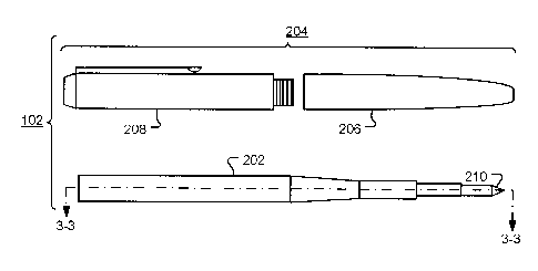
[0022] FIG. 2 is a schematic diagram of a combination ball-point pen
and
active stylus, in accordance with exemplary embodiments of the disclosure. The
combination ball-point pen and active stylus 102 includes active refill
cartridge 202
and pen housing 204. In operation, active refill cartridge 202 is placed
inside pen
housing 204 and the lower pen housing 206 and upper pen housing 208 are
screwed together. Once assembled, ball-point assembly 210 of the cartridge 202
protrudes from an aperture in the end of the lower pen housing 206. In
accordance
with one aspect of the disclosure, the combination ball-point pen and active
stylus
102 enables writing on paper or on a display of an electronic device. When the
combination ball-point pen and active stylus 102 is moved across paper,
friction
between the paper and a ball of the ball-point assembly 210 causes the ball to
rotate and transfer ink from the cartridge 202 to the paper. However, the
viscosity
of the ink within the cartridge is selected such that when the combination
ball-point
pen and active stylus 102 is moved across a display surface of a tablet, smart-
phone, or other electronic device, there is insufficient friction to overcome
the
surface tension of the ink and no ink is transferred to the display surface.
Instead,
a stylus signal is transmitted from the ball-point assembly 210. In one
embodiment, the ball-point assembly 210 operates as a radio antenna to enable
communication with a host electronic device. The pen housing 204 may include a
retraction mechanism operable to move the tip between an advanced position,
where the tip protrudes from the pen housing to allow deposition of writing
material
4
1
i
CA 02823500 2013-08-13
on a surface, and a retracted position, where the tip is disposed within the
pen
housing. A view through the cross-section 3-3 is shown in FIG. 3.
[0023] FIG. 3 is a sectional view of an exemplary active pen refill
cartridge
202. The active pen refill cartridge 202 comprises a hollow body 302
configured to
contain ink 304. The ink 304 is supplied to ball-point assembly 210 to enable
writing on paper. A circuit assembly 306 is operable to transmit a stylus
signal to
the ball-point assembly 210 to enable electronic drawing or writing. The
stylus
signal may be transmitted via a wire, via the hollow body 302, or via a
surface
coating on the hollow body 302. In this embodiment, the circuit assembly 306
is
powered by battery 308. The battery 308 may be electrically coupled to the
circuit
assembly 306 via one or more electrical connections 310. In one embodiment,
the
hollow body 302, or a coating on the hollow body, is electrically conductive
and
may be used to couple one pole of the battery, such as the ground, to the
circuit
assembly. The battery 308 may be located in a battery compartment 316 at the
end of the hollow body 302 to facilitate easy replacement of the battery 308.
A
terminal or contact pad 318 may be used to couple the battery to the circuit
assembly 306.
[0024] In one embodiment, the circuit assembly 306 is immersed in the ink
304. This configuration maximizes the amount of ink contained in the
cartridge.
[0025] The battery may be coupled to the circuit assembly via a switch.
The
switch may be, for example, included in a force sensing mechanism 312. In this
embodiment, the force sensing mechanism 312 is mechanically coupled to the
ball-
point assembly 210 via shaft 314. The shaft may be electrically conductive and
used to provide an electrical coupling between the circuit assembly 306 and
the
ball-point assembly 210. A compliant element 320 reduces the mechanical
coupling
between the ball-point assembly 210 and the end of the hollow body 302, so
that a
force applied to the ball-point assembly 210 is transferred to the force
activated
switch 312 via shaft 314. Additionally, the element 320 may be an electrical
insulator that prevents the stylus signal, supplied to the ball-point assembly
210,
from being electrically coupled to the hollow body 302. This enables hollow
body
CA 02823500 2013-08-13
302 to be used as power supply conductor. For example, the hollow body 302 may
be coupled to a battery and used as an electrical ground or supply voltage.
[0026] In some embodiments, the force-sensing mechanism 312 further
comprises a sensor configured to sense forces applied to the ball-point
assembly
210. When used as an active stylus, the circuit assembly is operable to
generate a
stylus signal that is descriptive of the force applied to the ball-point
assembly 210.
The force signal may be utilized by a host electronic device to control
selected
features of a drawing or writing application executed on the host electronic
device.
[0027] FIG. 4 is a block diagram of an exemplary circuit assembly of an
active stylus. The circuit assembly 306 includes a control module 400, which
may
be a micro-controller, a system on a chip (SoC), an assembly of discrete
components, an assembly of integrated circuits or a combination thereof, for
example. The control module 400 includes power management unit (PMU) 402,
which receives power from an external power supply, such as battery 308, and a
clock system (CLK S) 404 that receives a timing signal from a crystal (XTAL)
406.
The clock system is utilized, for example, to supply an instruction clock to
processing core 408. The clock system 404 may also supply a timing signal to a
radio transmitter 410. The radio transmitter 410 supplies a radio signal to
the ball-
point assembly 210. The ball-point assembly 210 operates as an antenna to
transmit the radio signal to a host electronic device. The control module 400
also
includes an analog-to-digital converter 412, operable to sample a force signal
414
from force-sensing mechanism 312. The force signal 414 is representative of a
force applied to the ball point assembly 210, which is mechanically coupled to
the
force sensing mechanism via coupling 314. The force-sensing mechanism 312 may
also receive a signal 416 from the control module 400 via digital-to-analog
converter 418.
[0028] In the embodiment shown in FIG. 4, an analog-to-digital converter
412 is used to provide a digital representation of the force signal. The
digital
representation may comprise one or more bits. For example, an 8-bit converter
might be used. When a single bit is used to indicate whether the force signal
is
6
1
CA 02823500 2013-08-13
above or below a threshold value, the analog-to-digital converter 412 may be
replaced by a switch.
[0029] The power management unit 402 may incorporate a battery monitor.
An indicator of the battery level may be embedded in the stylus signal and
communicated to a host electronic device, The host electronic device can then
display the battery level to a user, via the display screen, to facilitate
timely battery
replacement.
[0030] A further aspect of the disclosure relates to a writing implement
comprising a pen refill cartridge and an active stylus cartridge that are
constructed
and arranged to fit together within a pen housing. The pen refill cartridge
has a
hollow body, adapted to contain ink, and a ball-point assembly configured to
receive ink from within the hollow body and further configured to receive a
stylus
signal. A terminal at one end of the cartridge enables a stylus signal from
the
active stylus cartridge to be electrically coupled to the ball-point assembly.
The
active stylus cartridge includes a circuit assembly operable to produce a
stylus
signal, and a terminal is located at one end of the cartridge enables the
stylus
signal to be electrically coupled to the pen refill cartridge.
[0031] FIG. 5 is a sectional view of an exemplary active pen refill
cartridge
202, in accordance with an aspect of the disclosure. The active pen refill
cartridge
202 is arranged in two-parts, comprising a signal generation cartridge 502 and
antenna/ink cartridge 504. This embodiment facilitates replacement of the ink
cartridge 504 without having to replace the signal generation cartridge 502.
[0032] The antenna/ink cartridge 504 comprises a hollow body 302'
configured to contain ink 304. The ink 304 is supplied to ball-point assembly
210
to enable writing on paper. Electrical conductor 506 couples a stylus signal
from
terminal 508 to the ball-point assembly 210. The stylus signal may be
transmitted
via a wire, via the hollow body 302', or via a surface coating on the hollow
body
302'.
[0033] The signal generation cartridge 502 comprises a body 302" that
7
1
,
CA 02823500 2013-08-13
houses circuit assembly 306. The circuit assembly 306 is operable to transmit
a
stylus signal to antenna/ink cartridge 504 via terminal 510, which aligns with
electrical coupling 508 of antenna/ink cartridge 504 when the cartridges are
aligned
within a pen housing. The circuit assembly 306 is powered by battery 308. In
operation, signal generation cartridge 502 and antenna/ink cartridge 504 are
aligned in series inside a pen housing, such that a force applied to the ball-
point
assembly 210 pushes stop element 512 against an interior surface of the pen
housing and produces a force across force-sensing mechanism 312. The force-
sensing mechanism 312 may include a force-activated switch and/or a force
sensor
operable to sense the force applied to the ball-point assembly 210. The force
activated switch may be used to switch power to the circuit assembly 306. If
no
force is applied for a set period of time, the circuit assembly is de-powered.
This
enables the active stylus to be used in a 'hover' mode, in which the ball-
point
assembly is close to, but not touching, a display screen of an electronic
device.
When used as an active stylus, the circuit assembly is operable to generate a
stylus
signal that is descriptive of the force applied to the ball-point assembly
210, as
sensed by the force-sensor of the force-sensing mechanism 312. The force
signal
may be utilized by a host electronic device to control selected features of a
drawing
or writing application executed on the host electronic device.
[0034] The battery 308 may be placed in series with the force sensor, so
that
forces are coupled to the sensor through the battery, or the battery may be
placed
at other locations in the hollow body 302". The battery and housing therefor
may
be configured to enable easy replacement of the battery.
[0035] A stylus identifier may be embedded within the stylus signal and
transmitted to a host device. The identifier may be type identifier and/or a
unique
identifier the stylus.
[0036] FIG. 6 is a sectional view of an active an exemplary pen active
refill
cartridge 202 in accordance with an aspect of the disclosure. The active pen
refill
cartridge 202 comprises signal generation cartridge 502 and antenna/ink
cartridge
504. This embodiment allows the antenna/ink cartridge 504 to be replaced
without
8
1
1
CA 02823500 2013-08-13
having to replace the signal generation cartridge 502, and allows the battery
to be
replaced at the same time.
[0037] The antenna/ink cartridge 504 comprises hollow body 302' configured
to contain ink 304. The ink 304 is supplied to ball-point assembly 210 to
enable
writing on paper. Electrical conductor 506 couples a stylus signal from
terminal
508 to the ball-point assembly 210. The stylus signal may be transmitted via a
wire, via the hollow body 302', or via a surface coating on the hollow body
302'.
Battery 308 is electrically coupled to one or more terminals 602 to enable
power to
be supplied to the signal generation cartridge 502.
[0038] The signal generation cartridge 502 comprises body 302" that houses
circuit assembly 306. The circuit assembly 306 is operable to transmit a
stylus
signal to antenna/ink cartridge 504 via terminal 510, which aligns with
electrical
coupling 508 of antenna/ink cartridge 504. In operation, signal generation
cartridge 502 and antenna/ink cartridge 504 are aligned in series inside a pen
housing, such that a force applied to the ball-point assembly 210 pushes force-
sensing mechanism 312 against an interior surface of the pen housing. The
force-
sensing mechanism 312 may include a force-activated switch and/or a force
sensor
operable to sense the force applied to the ball-point assembly 210. The force
activated switch may be used to switch power to the circuit assembly 306. In
this
embodiment, the circuit assembly 306 is powered by battery 308 that is
electrically
coupled to the circuit assembly, through the force activated switch, when the
one or
more terminals 604 make contact with the mating terminals 602. If no force is
applied for a set period of time, the circuit assembly is de-powered. This
enables
the active stylus to be used in a 'hover' mode, in which the ball-point
assembly is
close to, but not touching, a display screen of an electronic device. When
used as
an active stylus, the circuit assembly is operable to generate a stylus signal
that is
descriptive of the force applied to the ball-point assembly 210, as sensed by
the
force-sensor of the force-sensing mechanism 312. The force signal may be
utilized
by a host electronic device to control selected features of a drawing or
writing
application executed on the host electronic device.
9
,
CA 02823500 2013-08-13
[0039] FIG. 7 shows an exemplary two-part active pen refill cartridge in
accordance with an aspect of the disclosure. The active pen refill cartridge
comprises signal generation cartridge 502 and antenna/ink cartridge 504. The
cartridges are shown positioned within the body of pen 102. The cartridges are
electrically coupled through terminal 510 of signal generation cartridge 502
and
terminal 508 of antenna/ink cartridge 504, enabling a stylus signal generated
in
signal generation cartridge 502 to be coupled to the antenna of antenna/ink
cartridge 504. Additional electrical connections may be used if the battery is
located in antenna/ink cartridge 504. A bias element 702 (such as a spring)
holds
the cartridges in the correct position and relieves force on the force-
activated
switch 512 when no force is applied to the ball-point assembly 210. In use, a
force
applied to ball-point assembly 210 is transferred to cartridge 502 and
compresses
bias element 702. This activates force-activated switch 512 to power the
signal
generation cartridge 502. Signal generation cartridge 502 may remain powered
for
a period of time after the force is removed from ball-point assembly 210.
[0040] In one embodiment, the signal generation cartridge 502 is provided
with an on/off switch that may be activated by user when the cartridge is
removed
from the pen body 102. This enables battery power to be conserved when writing
on paper.
[0041] In another embodiment, the signal generation cartridge 502 may be
powered on or off by tapping the ball-point assembly on a surface a set number
of
times within a period of time. Again, this enables battery power to be
conserved
when writing on paper.
[0042] In a further embodiment, the signal generation cartridge 502 is
permanently powered.
[0043] FIG. 8 is a flow chart 800 of a method of operation of a
combination
active stylus and ball-point pen. At start block 802, the circuit assembly is
powered-off or in a low power mode, so as to conserve battery life. Following
start
block 802, a start condition is detected at decision block 804. The start
condition
may be, for example, a user-activated switch, a force-activated switch, or
tapping
1
1
CA 02823500 2013-08-13
of the ball-point assembly on a surface. At block 806, the circuit assembly is
powered to enable full operation. If the start condition is caused by a force
activated switch, a timer is reset at block 808. The timer allows the circuit
assembly to remain powered for a period of time after a start condition is
detected.
Optionally, at block 810, the force applied to the ball-point assembly is
sensed,
using the force-sensing mechanism, and at block 812 a stylus signal is
generated.
The stylus signal, which may be representative of the force applied to the
ball-point
assembly, is transmitted to the antenna at block 814. At decision block 816, a
stop
condition is detected. The stop condition may be, for example, a user-
activated
switch, an absence of force on a force-activated switch, or tapping of the
ball-point
assembly on a surface. If a stop condition is not detected, as depicted by the
negative branch from decision block 816, flow returns to block 808 and the
timer is
reset. If the stop condition is caused by a force activated switch, a check is
made
at decision block 818 to determine if the timer has expired. If the timer has
expired, as depicted by the positive branch from decision block 818, the
circuit
assembly is de-powered or enters a low power operating mode at block 820.
Similarly, if the stop condition is the result of a user-activated switch or
tapping of
the ball-point assembly on a surface, the timer expiration period may be set
to zero
so that flow continues to block 820 when the stop condition is detected.
[0044] FIG. 9 is a block diagram of an exemplary active stylus. The
circuit
assembly 306 includes a control module 400, which may be a micro-controller, a
system on a chip (SoC), an assembly of discrete components, an assembly of
integrated circuits or a combination thereof, for example. In this embodiment,
the
stylus communicates with a host electronic device using near field
communication
(NFC) and the control module 400 is powered from a remote power source. The
remote power source comprises a plurality of inductors 902 close to the
surface of
the display screen 108 of a host electronic device. In operation, when stylus
tip
210 is positioned close to the inductor 902 of the host, the electromagnetic
field
produced by the inductor 902 of the host induces a current in an inductor 904
in
the tip of the stylus. The induced current is supplied to power management
unit
(PMU) 402 to produce power supply 906 for the control module 400. The radio
transmitter 410 supplies a radio signal to the ball-point assembly 210. This
may be
11
'
CA 02823500 2013-08-13
used to modify a property of the inductor 904 (such as the inductance,
resistance,
current etc) that may be sensed by the host electronic device.
[0045] In this embodiment, the stylus position is only detected when the
stylus tip is close to display screen 108 of a host electronic device. The
stylus is
inactive otherwise. By placing a sheet of paper over the display screen 108, a
user
may simultaneously create a drawing on the paper and on the electronic device.
[0046] FIG. 10 is a sectional view of an illustrative two-part active pen
refill
cartridge 202 in accordance with an aspect of the disclosure. In this
embodiment,
the pen refill cartridge 504 incorporates an ink level sensor comprising a
first probe
1002 electrically coupled to a first terminal 1004, and a second probe 1006
electrically coupled to a terminal 1008. Ink 304 is electrically conductive
and
completes a circuit between the first and second probes. The resistance of the
circuit is dependent upon the amount of ink in the cartridge - a full
cartridge will
have a lower resistance than an empty or partially empty cartridge. In
operation,
the first and second probes (1002, 1006) are coupled to signal generation
cartridge
502, via terminal 1010 and 1012, which in turn is operable to sense the
resistance
between the two probes. A signal indicative of the ink level may be embedded
in
the stylus signal and transmitted to a host electrical device via the ball-
point
assembly 210.
[0047] FIG. 11 is a sectional view through at lines 11-11 shown in FIG
10.
Ink 304 is contained within the hollow body 302' and forms an electrical
connection
between first probe 1002 and second probe 1004. The first and second probes
may
be implemented as coatings or traces on the non-conducting interior of the
hollow
body 302'. The width of the probes, or the spacing between the probes, may be
varied in different implementations and may be selected dependent upon the
electrical properties of the ink and/or the probes. For example, wider probe
spacing may be used for a more conductive ink. Once the resistance between the
probes is determined, the information may be embedded in a stylus signal
transmitted along insulated conductor 506 to the ball point assembly.
[0048] In a further embodiment, conductor 506 is not insulated, and the
ink
12
1
1
CA 02823500 2013-08-13
level is determined by measuring the resistance between the conductor 506 and
a
single probe.
[0049] In a yet another exemplary embodiment as shown in FIG. 12, the pen
refill cartridge 504 incorporates a sensor for determining when the ink level
is low.
In this embodiment, a first probe 1202 located in the hollow body 302' is
electrically coupled via insulated conductor 1204 to a first terminal 1206 and
a
second probe 1208 is electrically coupled via insulated conductor 1210 to a
second
terminal 1212. Conductive ink 304 provides an electrical connection between
the
first and second probes when the ink level is above the level of the probes.
However, no connection is provided when the ink level is below the level of
the
probes. The absence of a connection indicates that the ink level is low, and
this
information may be communicated to a host electronic device via the stylus
signal.
The first and second probes may be spaced apart in the longitudinal or
circumferential directions of the hollow body 302' and may be any shape. For
example, longitudinally spaced rings, or circumferentially spaced pads may be
used.
[0050] FIG. 13 is a further view of a pen refill cartridge 504
incorporating a
sensor for determining when the ink level is low. In this embodiment, a first
probe
1202 located in the hollow body 302' is electrically coupled via insulated
conductor
1204 to a first terminal 1206 and a second probe 1208 is electrically coupled
via
insulated conductor 1210 to a second terminal 1212. Conductive ink 304
provides
an electrical connection between the first and second probes when the ink
level is
above the level of the probes. However, no connection is provided when the ink
level is below the level of the probes. The absence of a connection indicates
that
the ink level is low, and this information may be communicated to a host
electronic
device via the stylus signal. The first and second probes may be spaced apart
in
the longitudinal or circumferential directions of the hollow body 302' and may
be
any shape. Circumferentially spaced pads are used in the exemplary embodiment
shown.
[0051] The implementations of the disclosure described above are intended
to
be merely exemplary. It will be appreciated by those of skill in the art that
13
1
CA 02823500 2013-08-13
alterations, modifications and variations to the illustrative embodiments
disclosed
herein may be made without departing from the scope of the disclosure.
Moreover,
selected features from one or more of the above-described embodiments may be
combined to create alternative embodiments not explicitly shown and described
herein.
[0052] The disclosure may be embodied in other specific forms without
departing from its spirit or essential characteristics. The described
exemplary
embodiments are to be considered in all respects only as illustrative and not
restrictive. The scope of the disclosure is, therefore, indicated by the
appended
claims rather than by the foregoing description. All changes that come within
the
meaning and range of equivalency of the claims are to be embraced within their
scope.
14
1