Note : Les descriptions sont présentées dans la langue officielle dans laquelle elles ont été soumises.
CA 02829681 2013-09-10
WO 2012/125300 PCT/US2012/027249
SELF CENTERING BORE MEASUREMENT UNIT
BACKGROUND OF THE INVENTION
[0001] The
present invention relates to the measurement of
bore diameters within hollow members.
Specifically, the
present invention is directed to a self centering bore
measurement unit.
[0002] It
is well known that accurate bore measurements of
hollow members provide important data in the analysis of the
members and the apparatuses which they form a part of. This
data is highly desirable in the manufacture and maintenance of
generator rotor bores, turbine shaft bores, and the like. For
example, initial bore diameter readings may be used to
determine whether a bore has been constructed to proper
specifications.
Additionally, bore creep or areas of high
stress may be revealed through periodic bore measurement
testing during use.
[0003] However, known techniques for measuring bore
diameters have limitations.
BRIEF SUMMARY OF THE INVENTION
[0004]
Current bore measurement devices are limited in
several manners. As
one example, they cannot measure the
entire length of bores that have certain geometries. They may
therefore be limited to measuring bores that do not include
bottle-necks or variances in cross-sectional diameter.
They
may also be limited to bores that are below certain overall
lengths.
Current bore measurement devices may also be
incapable of accurately measuring bores that include an
irregular surface within the bore itself, such as a dimple
created during a routine defect fixing procedure.
[0005]
Additionally, conventional bore measuring units are
limited to three measurement points around the bore diameter
at a particular linear position within the bore. Although it
will be recognized that three points are the minimal number of
-1-
CA 02829681 2015-05-05
' 54106-1454
points required to produce a circle, adding more data points to
the analysis creates a more accurate "best fit" reading of the
actual bore diameter.
[0006] Lastly, conventional bore measurement units must also
be specifically arranged for a single bore diameter. These
units cannot dynamically adjust to bores of different
diameters, let alone a single bore having a variable diameter.
[0007] In view thereof, the present invention provides for a
self centering bore measurement unit that is capable of
performing accurate bore measurements in bores of various
geometries and conditions. =
[0007a] According to one aspect of the present invention,
there is provided a bore measurement unit comprising: an
elongate main body having a first end and a second end; a first
adjustment mechanism disposed near said first end, the first
adjustment mechanism expanding or contracting to relative
diameters; a second adjustment mechanism disposed near said
second end, the second adjustment mechanism expanding or
contracting to relative diameters; a measuring portion
associated with said main body, the measuring portion adapted
to measure the internal diameter of the bore of a hollow
member; wherein when said elongate main body is inserted into a
bore of a hollow member, said first and second adjustment
mechanisms are expanded to generally center said elongate main
body within said bore such that said measuring portion is able
to measure the internal diameter thereof, wherein said first
adjustment mechanism comprises a fixed collar fixedly
positioned about said elongate main body, a sliding collar
configured in a sliding relation about said elongate main body,
-2-
CA 02829681 2015-05-05
54106-1454
and three arms connecting said first fixed collar to said first
sliding collar, said arms each being hinged to collectively
triangulate to form a relative diameter, wherein sliding of
said sliding collar toward said fixed collar increases the
relative diameter of said first adjustment mechanism and
sliding of said sliding collar away from said fixed collar
decreases the relative diameter of said first adjustment
mechanism.
[0007b]
According to another aspect of the present invention,
there is provided a method of measuring the inner bore diameter
of a hollow shaft, said method comprising: inserting an
elongate measuring device comprising a first adjustment
mechanism, a second adjustment mechanism, and a measuring
portion into the inner bore, the adjustment mechanisms
adjustable to relative diameters; adjusting the relative
diameters of the first adjustment mechanism and the second
adjustment mechanism such that the adjustment mechanisms each
abut the inner bore at their relative diameters to generally
center the elongate measuring device within the bore;
activating the measuring portion to take a plurality of
measurement readings of the inner bore in an area adjacent to
the measuring portion, wherein the first adjustment mechanism
used in the method comprises a fixed collar fixedly positioned
about an elongate main body of the elongate measuring device, a
sliding collar configured in a sliding relation about said
elongate main body, and three arms connecting said first fixed
collar to said first sliding collar, said arms each being
hinged to collectively triangulate to form a relative diameter,
wherein sliding of said sliding collar toward said fixed collar
increases the relative diameter of said first adjustment
-2a-
CA 02829681 2015-05-05
' 54106-1454
mechanism and sliding of said sliding collar away from said
fixed collar decreases the relative diameter of said first
adjustment mechanism.
[0008] In one embodiment a bore measurement unit may
comprise an elongate main body having a first end and a second
end, a first adjustment mechanism disposed near the first end,
the first adjustment mechanism expanding or contracting to
relative diameters, a second adjustment mechanism disposed near
the second end, the second adjustment mechanism expanding or
contracting to relative diameters, and a measuring portion
associated with the main body, the measuring portion adapted to
measure the internal diameter of the bore of a hollow member.
When the elongate main body is inserted into a bore of a hollow
member, the first and second adjustment mechanisms may be
expanded to generally center the elongate main body within the
bore such that the measuring portion may measure the internal
diameter thereof.
[0009] The first adjustment mechanism may comprise a fixed
collar fixedly positioned about the elongate main body, a
sliding collar configured in a sliding relation about the
elongate main body, and three arms connecting the first fixed
collar to the first sliding collar, the arms each being hinged
to collectively triangulate to form a relative diameter.
Sliding of the sliding collar toward the fixed collar may
increase the relative diameter of the first adjustment
mechanism while sliding of the sliding collar away from the
-2b-
CA 02829681 2013-09-10
WO 2012/125300 PCT/US2012/027249
fixed collar may decrease the relative diameter of the first
adjustment mechanism. In
other arrangements, this may be
opposite.
[0010] The
first adjustment mechanism may further comprise
a wheel associated with each hinged arm, the wheels positioned
at hinges of the arms at the relative diameter.
[0011] The
bore measurement unit may further comprise a
linear actuator coupling the sliding collar of the first
adjustment mechanism to the elongate body such that the linear
actuator moves the sliding collar relative to the elongate
body. The
linear actuator may be a pneumatically operated
magnetically coupled rodless cylinder, or other type of
actuator such as a screw driven actuator.
[0012] The first adjustment mechanism and the second
adjustment mechanism may be separably adjustable, the
adjustment mechanisms capable of forming two different
relative diameters such that the elongate member remains
centered in a bore having a variable diameter. In such case,
there may be two linear actuators.
[0013] The
measuring portion may comprise at least one
photoelectric distance sensor which rotates to sense distances
associated with the inner bore diameter of the hollow member
about 3600 cycles. The photoelectric distance sensor may take
at least four readings during each cycle for a total of at
least four distance readings. The
bore measurement unit may
further comprise a data collection and processing computer
with display, wherein the at least four distance readings are
collected and fitted to a best fit circle whose dimensions are
displayed on the display.
[0014] The
measuring portion may comprise two photoelectric
distance sensors, the photoelectric distance sensors each
rotating in at least 180 cycles and each taking at least two
distance readings during each cycle.
-3-
CA 02829681 2013-09-10
WO 2012/125300 PCT/US2012/027249
[0015] The measuring portion may measures the bore diameter
of the hollow member to within a tolerance of approximately
1/1000".
[0016] In another embodiment of the present invention, a
method of measuring the inner bore diameter of a hollow shaft
may comprise inserting an elongate measuring device comprising
a first adjustment mechanism, a second adjustment mechanism,
and a measuring portion into the inner bore, the adjustment
members adjustable to relative diameters; adjusting the
relative diameters of the first adjustment mechanism and the
second adjustment mechanism such that the adjustment
mechanisms each abut the inner bore at their relative
diameters to generally center the elongate measuring device
within the bore; and activating the measuring portion to take
a plurality of measurement readings of the inner bore in an
area adjacent to the measuring portion.
[0017] The method may further comprise moving the elongate
measuring device along the length of the inner bore and
activating the measuring portion to take a second plurality of
measurement readings of the inner bore in an area adjacent to
the measuring portion.
[0018] The moving step may comprise adjusting the relative
diameter of at least one of the adjustment mechanisms.
[0019] The step of inserting may be achieved by pushing the
elongate measuring device in the bore with a graduated
measuring rod. In such case, the method may further comprise
identifying the depth of penetration into the inner bore of
the measuring portion and moving the elongate measuring device
along the length of the inner bore a predetermined distance.
Then the method may include activating the measuring portion
to take a second plurality of measurement readings of the
inner bore in an area adjacent to the measuring portion.
[0020] The step of activating the measuring portion may
take at least three readings of the inner bore in an area
-4-
CA 02829681 2013-09-10
WO 2012/125300 PCT/US2012/027249
adjacent to the measuring portion. The
readings may be
conveyed to and stored in a data collection and processing
computer.
[0021] The
measurement portion may include two sensors,
each adapted to take measurement readings.
[0022] In
a further embodiment of the present invention, a
bore measurement unit for measuring the internal diameter of a
hollow member having a bore with a longitudinal axis may
comprise an elongate main body having a longitudinal axis, two
adjustment mechanisms associated with the main body, the
adjustment mechanisms each triangulating to expand and
position the longitudinal axis of the elongate main body along
the longitudinal axis of the bore when the elongate main body
is inserted therein, and a rotating sensor, the rotating
sensor taking a plurality of readings of the internal diameter
of the hollow member.
BRIEF DESCRIPTION OF THE DRAWINGS
[0023] The
above description, as well as further objects,
features and advantages of the present invention will be more
fully understood with reference to the following detailed
description of the self centering bore measurement unit when
taken in conjunction with the accompanying drawings, wherein:
[0024]
Fig. 1 depicts a schematic view of a bore measuring
unit in accordance with one embodiment of the present
invention;
[0025]
Fig. 2 depicts a detailed schematic view of the
first adjustment mechanism of the bore measurement unit of
Fig. 1;
[0026]
Fig. 3 depicts a partial cross-sectional view of the
bore measurement unit of Fig. 1;
[0027]
Figs. 4A and 4B depict detailed views of the
measuring portion of the bore measurement unit of Fig. 1 with
one sensor and two sensors, respectively; and,
-5-
CA 02829681 2013-09-10
WO 2012/125300 PCT/US2012/027249
[0028]
Fig. 5 depicts the bore measuring unit of Fig. 1 in
use within the bore of a hollow member.
DETAILED DESCRIPTION
[0029] In
describing the preferred embodiments of the
subject matter illustrated and to be described with respect to
the drawings, specific terminology will be resorted to for the
sake of clarity. However, the invention is not intended to be
limited to the specific terms so selected, and it is to be
understood that each specific term includes all technical
equivalents which operate in a similar manner to accomplish a
similar purpose.
[0030]
Described herein are embodiments of the self
centering bore measurement unit of the present invention. The
bore measurement unit is designed to measure the inner bore
diameter of hollow members such as generator rotor bores,
turbine shaft bores, and the like. It is envisioned that the
bore measurement unit be capable of measuring bores with
internal diameters in the range of approximately 4"0 to 12"0
and be accurate to within approximately 0.001" (or
approximately 25.4 microns). Ideally, the bore measuring unit
is capable of measuring bore diameters at least as small as
4.25"0.
Additionally, the bore measurement unit may measure
bores within hollow members of upwards of 50 feet in length or
more. The measurements may be taken prior to start-up of the
hollow member or periodically during use, for example once per
year.
[0031]
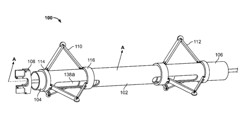
Fig. 1 depicts a schematic view of a bore
measurement unit 100 in accordance with one embodiment of the
present invention. As shown in Fig. 1, the bore measurement
unit includes an elongate and cylindrical main body 102 having
a first end 104 and a second end 106. The
first end 104
includes a measurement portion 108 adapted to detect
measurements of the internal bore diameter of hollow members
within which the bore measurement unit is inserted. Between
-6-
CA 02829681 2013-09-10
WO 2012/125300 PCT/US2012/027249
the first end and second end 104, 106 of the bore measurement
unit 100, and preferably near the first end and second end
respectively, are spaced apart adjustment mechanisms in the
form of a first adjustment mechanism 110 and second adjustment
mechanism 112. As will be discussed, the adjustment
mechanisms 110, 112 alter the overall diameter of the bore
measurement unit 100 and maintain the main body 102 in an
orientation which is parallel to, and centered within, an
internal bore of a hollow member.
[0032] Moving to Fig. 2, there is shown a detailed
schematic view of the first adjustment mechanism 110 of the
bore measurement unit 100. The mechanism consists of several
components, including a fixed collar 114 and a sliding collar
116, both of which are generally annular in shape.
[0033] As
the name suggests, the fixed collar 114 is
fixedly attached to the main body 102, for example by welding,
chemical bonding, or mechanical fixation. The
fixed collar
114 includes three ears, 118a, 118b, 118c, preferably spaced
at 120 intervals around the fixed collar, the ears facing the
sliding collar 116.
Each of the ears includes an aperture
(not visible in the drawings) through which pins 120a, 120b,
120c may be driven to form pivot axes.
[0034] The
sliding collar 116 is arranged similarly to the
fixed collar 114, and also includes ears 122a, 122b, 122c,
preferably spaced at 120 intervals around the sliding collar,
or at least at intervals corresponding to those of the ears
118a, 118b, 118c of the fixed collar.
Ears 122a, 122b, 122c
face the fixed collar 114 and include apertures (not visible
in the drawings) through which pins 124a, 124b, 124c may be
driven to form pivot axis. Unlike the fixed collar 114, the
sliding collar 116 is not fixed in longitudinal relation to
the main body 102.
[0035]
Connecting the corresponding ears, i.e. ear 118a to
ear 122a, ear 118b to ear 122b, and ear 118c to ear 122c, are
-7-
CA 02829681 2013-09-10
WO 2012/125300 PCT/US2012/027249
three pairs of arms, 126a, 126b, 126c.
Each of the arms
articulates about joints 128a, 128b, 128c formed at the
junction between first arm segments 130a, 130b, 130c and
second arm segments 132a, 132b, 132c. It
will be appreciated
that the first arm segments 130a, 130b, 130c and second arm
segments 132a, 132b, 132c may be equal in length or may differ
in length. However, it is preferred that at least all of the
first arm segments 130a, 130b, 130c be of equal length and all
of the second arm segments 132a, 132b, 132c also be of equal
lengths, even if different than the first arm segments.
Additionally, the overall lengths of arms 126a, 126b, 126c
should preferably be equal.
[0036] The joints 128a, 128b, 128c are formed from
corresponding apertures (not visible in the drawings) of the
first arm segments 130a, 130b, 130c and second arm segments
132a, 132b, 132c, which are pinned together by pins 134a,
134b, 134c. Sandwiched within each joint 128a, 128b, 128c are
wheels 136a, 136b, 136c which are arranged to roll freely
along the longitudinal axis of the main body 102, for example
by rotating around the respective pins 134a, 134b, 134c.
Preferably, the wheels are non-marring and include relatively
easy rolling bearings.
[0037]
Although not described in detail herein, it will be
appreciated that the second adjustment member 112 is
configured in much the same manner as the first adjustment
member 110.
[0038]
Referring back to Fig. 1, the main body 102 is shown
with a pair of longitudinally aligned slots each associated
with one of the adjustment members 110, 112.
Using first
adjustment member 110 as an example, it is shown that the slot
138a extends from a point between the fixed collar 114 and the
sliding collar 116 to a point outside the sliding collar 116.
Not shown in Fig. 1 are additional slots located 180 around
-8-
CA 02829681 2013-09-10
WO 2012/125300 PCT/US2012/027249
the main body 102 from the two slots shown.
Slots in this
1800 relation are shown in Fig. 3 as slots 138a, 138b.
[0039]
Fig. 3 depicts a partial cross-sectional view of the
bore measurement unit 100 of Fig. 1. Within the interior of
the bore measurement unit 100, and associated with the first
adjustment mechanism 110, there are shown a pair of spaced
apart actuator supports 140a, 140b. The
actuator supports
140a, 140b may be generally circular bodies with a hollow
central area 142a, 142b and a plurality of cutouts 144a, 144b,
144c, 144d. The supports 140a, 140b support a linear
actuator, preferably in the form of a magnetically coupled
rodless cylinder 146, that spans between the two supports.
The magnetically coupled rodless cylinder 146 is positioned
through the hollow central areas 142a, 142b and may be held in
place with mechanical hardware such as bolts 149a, 149b on the
outsides of the respective supports. The cutouts 144a, 144b,
144c, 144d of the actuator supports 140a, 140b provide
pathways for wires and the air supply to travel. As will be
discussed, the wires are for power and signaling of
electronics such as a motor and sensor and the air supply is
for operation of pneumatic elements.
[0040] It
will be appreciated that the magnetically coupled
rodless cylinder 146 includes a mount 148 that travels along
the cylinder under the influence of air pressure or vacuum, in
the conventional manner. Thus, an air tap 150 provided on the
magnetically coupled rodless cylinder 146 is connected to an
air hose 152, as shown in Fig. 3. The
air hose is in turn
connected to an air supply that provides standard "shop air"
in the range of approximately 90 psi to expand the adjustment
mechanisms 110, 112. Upon removal of the "shop air," the
adjustment mechanisms 110, 112 are permitted to return to a
contracted condition putting the bore measurement unit 100 in
the configuration of its smallest diameter.
This is
advantageous, for example, when removing the bore measurement
-9-
CA 02829681 2013-09-10
WO 2012/125300 PCT/US2012/027249
unit 100 from a bore, as will be discussed.
Magnetically
coupled rodless cylinders suitable for this application
include those provided as Series NCY3B by the SMC Corporation.
[0041]
Connected to the mount 148 are a pair of actuator
attachments 154a, 154b. The actuator attachments 154a, 154b
attach to the mount 148 and each include an extension portion
156a, 156b that is sized and configured to fit firmly within
the slots 138a, 138b, respectively, and to travel within the
slots. As
air is provided or removed from the magnetically
coupled rodless cylinder 146 through the air tap 150, the
mount 148 slides along the magnetically coupled rodless
cylinder and therefore the main body 102, bound only by the
limits of the slots 138a, 138b. This movement causes the legs
126a, 126b, 126c of the first adjustment mechanism 110 to
expand or contract, thus altering the overall diameter of the
bore measurement unit 100.
[0042] At
the first end 104 of the bore measurement
apparatus, and forming the measurement portion 108, are
components adapted for measuring the inner bore diameter of a
hollow member within which the bore measurement unit 100 is
inserted.
Toward this end, the measurement portion 108
includes a motor encoder 158 positioned within the main body
102. The motor encoder 158 is an electric motor that spins a
shaft 160 while converting the angular position of the shaft
to an analog or digital code that may be read by a computer
processor, such as that to be described. In
addition, the
shaft may also include a proximity sensor (not shown), to also
read the angular start/stop position. The shaft 160 includes
a portion 160a within the main body 102, and a portion 160b
outside the main body. The shaft 160 is held in place with a
slip ring 162 forming the end of the main body 102, the slip
ring permitting rotation of the shaft without electrical wires
of the sensor being an impediment. Connected to the shaft 160
at its outside portion 160b is a sensor support 164, in the
-10-
CA 02829681 2013-09-10
WO 2012/125300 PCT/US2012/027249
case of Fig. 3 being a double sensor support. The
sensor
support 164 holds one or more sensors 166a, 166b firmly in
place while the shaft 160 spins the entire sensor support and
sensor combination. It
is important that the sensor support
hold the sensors 166 firmly such that the sensors 166 do not
shift during use, which might introduce errors in the distance
readings.
[0043] The sensors 166 are preferably photoelectric
distance sensors that are not sensitive to surface finish in
the manner of laser sensors, although they may also be
configured as other types of sensors such as laser sensors.
Preferably, the sensors 166 are of the type manufactured by
the Baumer Electronic company, such as model OADM12.
[0044] In
the embodiment shown in Fig. 3, the sensors 166a,
166b are diametrically opposed from each other such that an
entire 360 internal diameter reading may be obtained from a
motor sweep of 180 .
However, space considerations may
require that a single sensor 166a be utilized. In
such case,
the sensor 166 can be swept through the full 360 's of
revolution for each internal diameter reading.
Figs. 4A and
4B depict enlarged views of a single sensor 166a measurement
portion 108 and a double sensor 166a, 166b measurement
portion, respectively. Of
course, more than two sensors may
also be utilized.
[0045]
Shown in Fig. 5 is a bore measurement unit 100
inserted within a bore of a hollow member (M). As
shown in
Fig. 5, the complete bore measurement unit 100 also includes a
data collection and processing computer, or computer processor
(P), which is connected to the electronics of the unit,
including the motor encoder 158 and one or more sensors 166.
Preferably, the computer processor (P) includes a display to
indicate past readings and other information.
[0046] To
insert the bore measurement unit 100, an operator
will place the unit in its smallest diameter configuration,
-11-
CA 02829681 2013-09-10
WO 2012/125300 PCT/US2012/027249
with the adjustment mechanisms 110, 112 fully retracted or
nearly so. The unit 100 may then be placed within the bore of
a hollow member (M). Air may then be slowly introduced into
the magnetically coupled rodless cylinders 146 of each
adjustment mechanism 110, 112, which may be through a common
header or independently, depending on the physical arrangement
and needs of the operator. For
example, complex inner bore
diameters may require independent adjustment. The
air moves
the mounts 148 within the slots 138 and thereby expands the
adjustment mechanisms 110, 112.
This expansion causes the
wheels 136 to abut the inner diameter of the hollow member
(M), while centering the bore measurement unit 100 along a
common longitudinal centerline (CL) of the hollow member (M)
and the bore measurement unit 100.
[0047] A
rod (R) may be used to push the bore measurement
unit 100 into the hollow member.
Preferably, the rod (R) is
indexed such that internal diameter readings may be taken at
fixed intervals. The
insertion may be achieved manually, in
which case an operator can align the indexes with a fixed
position, such as the extreme second end 106 of the bore
measurement unit 100, or with an electronic displacement
mechanism. Air
pressure in the magnetically coupled rodless
cylinders 146 may be adjusted to account for differing
diameters of the hollow member (M) as the bore measurement
unit 100 is advanced into the bore.
Bores of upwards of 50
feet or more may be measured by adding to the length of the
rod (R), for example by adding screw-on segments.
[0048] The
fixed interval for readings may be on the order
of 1/4" to several inches, and is generally approximately
every inch. As such, at every inch (or other fixed interval)
of insertion, a best fit circle of the inner bore diameter of
the hollow member (M) is taken, and recorded by the computer
processor. In
the manual insertion operation, the operator
may enter a keystroke into the computer processor (P) to
-12-
CA 02829681 2015-05-05
54106-1454
advise that a new reading should be taken. In such case, the
excursion of the bore measurement unit 100 into the hollow
member (M) may be manually entered. Where
the bore
measurement unit 100 is inserted automatically, the operation
may be automated.
[0049] A
minimum of three bore diameter readings may be
taken at each interval, three bore diameters representing the
minimum number of readings necessary to complete a best fit
circle.
Preferably, many more diameters may be read, for
example one at each degree of rotation. As a greater number
of diameter readings are taken at each interval, more
computing power and storage capabilities are necessary. As
such, the manufacturer may decide a proper balance between
system requirements and sensitivity.
Preferably, the system
is set up to take at least one reading for each degree of the
360 diameter. The
proximity sensor (not shown) may be
utilized to ensure that the sensors achieve a full sweep of
rotation, be that 360 for a single sensor or 180 for a
double sensor setup.
[0050] Upon
reading of bore diameters throughout the hollow
member, or through whatever portion is desired, the bore
measurement unit 100 may be removed. This
is achieved by
withdrawing the rod (R) in the manual operation or reversing
operation of the automated insertion operator. Again, air
pressure may be adjusted periodically as necessary.
[0100]
Although the invention herein has been described
with reference to particular embodiments, it is to be
understood that these embodiments are merely illustrative of
the principles and applications of the present invention. It
is therefore to be understood that numerous modifications may
be made to the illustrative embodiments and that other
arrangements may be devised without departing from the
scope of the present invention as defined by the appended
claims.
-13-