Note : Les descriptions sont présentées dans la langue officielle dans laquelle elles ont été soumises.
CA 02839190 2013-12-11
WO 2012/174106
PCT/US2012/042248
- 1 -
COMPOSITES UTILIZING POLYMERIC CAPSTOCKS AND METHODS OF
MANUFACTURE
CROSS-REFERENCE TO RELATED APPLICATIONS
[0001] This application claims priority to and the benefit of U.S.
Provisional Patent
Application Serial No. 61/496,273, filed on June 13, 2011, the disclosure of
which is hereby
incorporated by reference herein in its entirety.
FIELD OF THE INVENTION
[0002] This invention relates to systems and methods for fabricating
extruded wood-plastic
composites and, more particularly, to systems for fabricating extruded wood-
plastic composites
that include a capstock having an elastomer and/or a plastomer.
BACKGROUND OF THE INVENTION
[0003] In the past 25 years, a new type of material has entered the
plastics products market.
Commonly referred to as wood-plastic composites (WPCs), fiber-plastic
composites, or plastic
composites (PCs), the new materials have been accepted into the building
products markets in
applications such as outdoor decking and railing, siding, roofing and a
variety of other
products. The market for WPCs has grown, and WPCs are now used in automotive
applications, as well as in the building products market, where they compete
with wood and
other plastic products.
[0004] A wood-plastic composite is a blended product of wood, or other
natural fibers, and
a thermoplastic material. The products can be produced with traditional
plastics processes,
such as extrusion or injection molding. For example, many building products
are produced
using extrusion processing similar to conventional plastics processing. The
wood and plastics
materials are blended before or during the extrusion process. The current WPC
materials are
CA 02839190 2013-12-11
WO 2012/174106
PCT/US2012/042248
- 2 -
most often compounds of wood, or natural fibers, and polyethylene,
polypropylene, or
polyvinyl chloride (PVC).
[0005] Presently available WPCs, however, suffer from certain drawbacks.
For example, if
the composite contains too high or too low of a ratio of plastic to wood, the
finished product
may not have the desired visual appearance or structural performance
characteristics. Such
products are less desirable in the marketplace. Additionally, WPCs may be
expensive to
produce due to, for example, the high cost of thermoplastic materials and
other additives used
in manufacture.
[0006] Ironically, many consumers expect WPCs to appear similar to wood,
but also expect
WPCs to perform as a robust plastic compound. To increase performance,
manufacturers often
incorporate UV stabilizers, antioxidants, biocides, color, fire retardants, or
other additives into
the WPC formulation. These additives, however, can increase manufacturing
costs of the
product, even though certain additives provide noticeable benefit only on a
limited location on
the product (e.g., in the case of UV stabilizers, the benefit only effects the
exterior of the
product that is exposed to sunlight).
[0007] To reduce the amount of additives that are incorporated into the
product,
capstocking is often used. In general, capstocks are coextruded with the core
material to form a
thin layer of polymer over the core extruded material. Various additives may
be incorporated
into the capstock, rather than in the core material, thus reducing the total
amount of additives
per linear foot of product. These capstocks, however, may suffer from
delamination from the
underlying WPC and may crack or otherwise fail, causing an unsightly
appearance, impaired
performance, and consumer dissatisfaction.
[0008] With certain capstocks, to improve adhesion, a discrete tie layer
is placed between
the core material and capstock, but this tie layer can present a number of
problems. For
CA 02839190 2013-12-11
WO 2012/174106
PCT/US2012/042248
- 3 -
example, the bond formed by the tie layer may separate over time from one or
both of the
capstock and core material, leading to product failure. Bond separation may
occur, for
example, due to differences in rates of expansion and contraction between the
core material and
the capstock. Also, water, ice, dirt, pollen, or other materials may penetrate
the capstock layer
through, for example, gaps at the edges of discrete capstock sections.
Additionally,
manufacturing costs of capstocked products utilizing a discrete tie layer tend
to be high, since
the tie layer must be applied to finished capstock and core materials. Another
type of capstock
material is ionomer-based. See, for example, U.S. Application Serial No.
12/643,442,
published as U.S. Patent Application Publication No. 2010/0159213, the
disclosure of which is
hereby incorporated by reference herein in its entirety.
[0009] There is a need for a capstocked WPC that provides improved
resistance to
moisture, sunlight, delamination, and cracking.
SUMMARY OF THE INVENTION
[0010] Described herein are extruded composite building materials that
include a capstock
including an elastomer and/or a plastomer. The building materials may be used
in a wide range
of building products, including decking, siding, trim boards, windows, doors,
fencing, and
roofing. Compared to previous composite building materials, embodiments of the
materials
described herein can offer several advantages, including a modified or greater
coefficient of
friction (i.e., improved slip resistance), improved mechanical resistance to
wear, abrasion,
scratching and the like (e.g., greater durability or toughness), and improved
chemical resistance
(e.g., greater resistance to extreme weather, UV, and/or moisture).
[0011] In one aspect, the invention relates to an extruded composite
adapted for use as a
building material. The extruded composite includes a core having a base
polymer and a filler
material in a substantially homogeneous mixture. The extruded composite also
includes a
CA 02839190 2013-12-11
WO 2012/174106
PCT/US2012/042248
- 4 -
capstock that includes an elastomer and/or a plastomer and is disposed on at
least a portion of
the core. When the capstock includes the plastomer, then (a) the extruded
composite is
substantially free of a compatibilizer, and/or (b) when the filler material
includes a natural
fiber, the natural fiber has or includes a moisture content greater than about
0.5 percent.
[0012] In certain embodiments, the base polymer is polypropylene,
polyethylene, HDPE,
MDPE, LDPE, LLDPE, and/or combinations thereof. The filler material may
include natural
fiber such as wood chips, wood flour, wood flakes, sawdust, flax, jute, hemp,
kenaf, rice hulls,
abaca, and/or combinations thereof. In one embodiment, the capstock also
includes a capstock
polymer, and the capstock polymer and the elastomer and/or the plastomer form
or include a
substantially homogeneous mixture. The base polymer may include a first
polymer (e.g.,
HDPE) and the capstock polymer may include the first polymer. In some
embodiments, the
capstock includes an additive that is or includes a colorant, a variegated
colorant, a UV
stabilizer, an antioxidant, an antistatic agent, a biocide, and/or a fire
retardant.
[0013] In various embodiments, the core includes from about 35% to about
50% base
polymer, by weight. The capstock may include from about 1% to about 30% of the
elastomer
and/or the plastomer, or from about 5% to about 20% of the elastomer and/or
the plastomer, by
weight. In some embodiments, the capstock includes from about 70% to about 99%
capstock
polymer, or from about 80% to about 95% capstock polymer, by weight. A
thickness of the
capstock may be, for example, from about 0.012 inches to about 0.040 inches,
or from about
0.015 inches to about 0.020 inches.
[0014] In certain embodiments, the capstock includes the elastomer, and
the elastomer
includes a propylene based elastomer, an ethylene propylene diene monomer, a
three block
thermoplastic elastomer, and/or a two block thermoplastic elastomer. In one
embodiment, the
capstock includes the plastomer, and the plastomer includes very low density
polyethylene,
CA 02839190 2013-12-11
WO 2012/174106
PCT/US2012/042248
- 5 -
metallocene polyethylene, and/or ethylene methacrylate. The filler material
may include an
inorganic filler (e.g., calcium carbonate, fly ash, and/or talc). The extruded
composite may also
include crumb rubber (e.g., in the capstock and/or the core).
[0015] In another aspect, the invention relates to a method of
manufacturing an extruded
a base polymer; providing a filler material; mixing and heating the base
polymer and the
filler material to produce a base mixture that is or includes a substantially
homogeneous melt
blend; providing a capstock material having an elastomer and/or a plastomer;
and coextruding
the capstock material onto at least a portion of the base mixture through a
die to form an
[0016] In certain embodiments, the method includes providing a capstock
polymer, and
mixing and heating the capstock polymer and the capstock material to produce a
capstock
[0017] In some embodiments, the method includes cooling the extruded
profile by passing
the extruded profile through a liquid. The coextruding may occur, for example,
in a single step
CA 02839190 2013-12-11
WO 2012/174106
PCT/US2012/042248
- 6 -
from constituent materials. In one embodiment, the capstock material includes
the elastomer,
and the elastomer includes a propylene based elastomer, an ethylene propylene
diene monomer,
a three block thermoplastic elastomer, and/or a two block thermoplastic
elastomer.
Alternatively or additionally, the capstock material may include the
plastomer, and the
plastomer may include very low density polyethylene, metallocene polyethylene,
and/or
ethylene methacrylate. The filler material may include an inorganic filler
(e.g., calcium
carbonate, fly ash, and/or talc). The method may also include the step of
providing crumb
rubber for incorporation into the base mixture and/or the capstock material.
[0018] Herein, unless otherwise noted, the use of one material when
describing a particular
application, process, or embodiment does not limit the described application,
process, or
embodiment to the specific material identified. The materials may be used
interchangeably, in
accordance with the described teachings herein. Additionally, unless otherwise
noted, the
terms WPCs, PCs, fiber-plastic composites, and variations thereof are used
interchangeably.
BRIEF DESCRIPTION OF THE DRAWINGS
[0019] Other features and advantages of the present invention, as well
as the invention
itself, will be more fully understood from the following description of the
various
embodiments, when read together with the accompanying drawings, in which:
= FIG. 1 is a schematic, perspective view of a capstocked WPC, in
accordance
with one embodiment of the present invention;
= FIG. 2 is a schematic, perspective view of a system for extruding a
capstocked
WPC, in accordance with another embodiment of the present invention;
= FIG. 3 is a cross-sectional schematic representation of a system for
extruding a
capstocked WPC, in accordance with another embodiment of the present
invention;
CA 02839190 2013-12-11
WO 2012/174106
PCT/US2012/042248
- 7 -
= FIGS. 4A and 4B are schematic representations of a process line for
forming a
capstocked WPC, in accordance with another embodiment of the present
invention;
= FIG. 5 is a schematic, end view of a co-rotating twin screw extruder used
in a
system for forming a capstocked WPC, in accordance with another embodiment of
the present
invention;
= FIG. 6 is a schematic, perspective view of a Y-block adapter and
extrusion die
assembly used in a system for forming a capstocked WPC, in accordance with
another
embodiment of the present invention;
= FIG. 7A depicts schematic side section and front views of a coextrusion
die
assembly used in a system for forming a capstocked WPC, in accordance with
another
embodiment of the present invention;
= FIG. 7B depicts schematic inlet, side section, and outlet views of the
plates of
the coextrusion die assembly of FIG. 7A, in accordance with another embodiment
of the present
invention;
= FIG. 7C depicts enlarged partial side section views of the coextrusion
die
assembly of FIG. 7A, in accordance with another embodiment of the present
invention;
= FIG. 8 is a plot depicting a relationship of capstock formulation to
adhesion
strength, in accordance with another embodiment of the present invention; and
= FIG. 9 is a plot depicting a relationship of capstock formulation to slip
resistance, in accordance with another embodiment of the present invention.
DETAILED DESCRIPTION OF THE INVENTION
[0020] As used herein, "plastomer" is understood to mean a non-ionomeric
copolymer that
includes ethylene and/or propylene.
CA 02839190 2013-12-11
WO 2012/174106
PCT/US2012/042248
- 8 -
[0021] As used herein, "compatibilizer" is understood to mean an agent
that has a primary
function to improve the wetting of a polymer on a natural fiber, such as wood
fiber. Examples
of such compatibilizers include titanium alcoholates, esters of phosphoric,
phosphorous,
phosphonic, and silicic acids, metallic salts and esters of aliphatic,
aromatic, and cycloaliphatic
acids, ethylene/acrylic or methacrylic acids, ethylene/esters of acrylic or
methacrylic acid,
ethylene/vinyl acetate resins, styrene/maleic anhydride resins or esters
thereof,
acrylonitrilebutadiene styrene resins, methacrylate/butadiene styrene resins
(MBS), styrene
acrylonitrile resins (SAN), and butadieneacrylonitrile copolymers. Other
examples of
compatibilizers include modified polyethylene and modified polypropylene,
which are obtained
by modifying polyethylene and polypropylene, respectively, using a reactive
group, including
polar monomers such as maleic anhydride or esters, acrylic or methacrylic acid
or esters,
vinylacetate, acrylonitrile, and styrene.
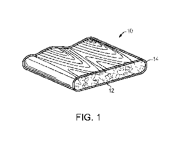
[0022] FIG. 1 shows one embodiment of a capstocked extruded wood-plastic
composite 10
(WPC) in accordance with the present invention. The extruded WPC 10 generally
includes a
dimensional composite body or core 12 formed from a mixture including one or
more base
polymers and natural fibers or other fillers. The base polymers may include
polypropylene,
polyethylene, HDPE, MDPE, polypropylene, LDPE, LLDPE, like materials, and
combinations
thereof. The natural fibers or filler materials help to provide the extruded
core 12 with the
appearance and feel of a natural wood product. Types of natural fibers, such
as wood fillers or
the like, include wood chips, wood flour, wood flakes, sawdust, flax, jute,
abaca, hemp, kenaf,
rice hulls, like materials, and combinations thereof. The use of such fillers
can reduce the
weight and cost of the core 12. Additionally, the core 12 may include
additives such as
colorants, lubricants, flame retardants, mold inhibitors, biocides, UV
stabilizers, antioxidants,
antistatic additives (e.g., to reduce dust attraction), other materials, and
combinations thereof.
CA 02839190 2013-12-11
WO 2012/174106
PCT/US2012/042248
- 9 -
[0023] In certain embodiments, the natural fibers have a moisture
content from about 0.5%
to about 5%. In other embodiments, the moisture content of the natural fibers
is from about 1%
to about 3%. For example, the moisture content of the natural fibers may be
about 2%.
[0024] In some embodiments, the natural fibers are replaced by or
supplemented with other
types of fillers. For example, the core 12 may include inorganic fillers
and/or natural or
synthetic elastomers in various forms, such as crumb rubber in different
grades and mesh sizes,
including pulverized crumb rubber. The inorganic fillers may be or may
include, for example,
calcium carbonate, talc, bottom ash, and/or fly ash. The talc may be, for
example, talcum
powder. The crumb rubber may have a mesh size ranging from about 4 to about
100, or from
about 20 to about 40, or about 30. The crumb rubber may be of any grade, for
example from
No. 1 to No. 5, or from No. 1 to No. 3, or preferably of grade No. 2 or No. 3.
The crumb
rubber may be or include any type of rubber, including natural rubber,
synthetic rubber, a
thermoset, and/or a thermoplastic. For example, the crumb rubber may include
SBR, nitrile, or
other synthetic variations. The natural fibers and/or other fillers may be
dispersed within the
core and held in place with the base polymer.
[0025] The core 12 is coated at least on one side by a capstock 14 that
includes a capstock
polymer and an elastomer and/or a plastomer. The capstock polymer may be any
polymeric
material capable of providing the desired mechanical, chemical, and thermal
properties. In
certain embodiments, the capstock polymer includes a polyolefin, such as
polyethylene and/or
polypropylene. In one embodiment, the capstock polymer is polyethylene (e.g.,
HDPE, product
6007 manufactured by Chevron Phillips).
[0026] Similarly, the elastomer may be any type of elastomer that
provides the capstock 14
with the desired mechanical, chemical, and thermal properties. Suitable
elastomers include
propylene based elastomers, ethylene propylene diene monomer (EPDM), three
block
CA 02839190 2013-12-11
WO 2012/174106
PCT/US2012/042248
- 10 -
thermoplastic elastomers (TPEs), and two block TPEs. The propylene based
elastomers refer
to those propylene products that have been produced using specific molecular
architecture and
a tightly controlled molecular weight range. This is unlike the modified
polypropylenes
referred to above as compatibilizers. These compatibilizers are polypropylene
molecules that
have had maleic anhydride or similar graftings to realize the modification. An
example of a
propylene-ethylene based elastomer is VERSIFY, manufactured by Dow Chemical,
of
Midland, MI. An example of an EPDM is VISTALONTm, manufactured by Exxon Mobil,
of
Irving, Texas. Examples of three block TPEs are styrene-ethylene/butylene-
styrene (SEBS),
such as KRATON G, block copolymers of styrene and butadiene, such as KRATON D
(SBS),
and polymers based on styrene and isoprene, such as Kraton D (SIS),
manufactured by Kraton
Performance Polymers Inc. of Houston, TX. A weight percentage of elastomer in
the capstock
may be between about zero and about 50%, between about 5% and about 30%,
between about
10% and about 20%, or about 5%.
[0027] Likewise, the plastomer may be any type of plastomer that
provides the capstock 14
with the desired mechanical, chemical, and thermal properties. Suitable
plastomers include
very low density polyethylene (VLDPE), metallocene polyethylene (PE), and
ethylene
methacrylate (EMA). In one embodiment, the propylene based elastomers,
described above,
are plastomers, in addition to being elastomers, and are therefore suitable
for use in the
capstock 14 as a plastomer and/or an elastomer. VLDPE and metallocene PE may
be obtained
from Dow Chemical or Exxon Mobil. EMA may be obtained from Dow Chemical. A
weight
percentage of plastomer in the capstock may be between about zero and about
50%, between
about 5% and about 30%, between about 10% and about 20%, or about 5%.
[0028] In certain embodiments, the base polymer facilitates adhesion
between the capstock
14 and the extruded WPC 10, particularly when the base polymer and the
capstock polymer are
CA 02839190 2013-12-11
WO 2012/174106
PCT/US2012/042248
-11 -
the same (e.g., HDPE). Since polymers such as polyethylene weather rapidly
under certain
conditions, inclusion of additives and stabilizers also may improve exterior
weather
performance. The elastomers and/or the plastomers, along with the additives
and stabilizers,
provide improved surface properties over those of uncoated extruded WPC. The
elastomeric
and/or plastomeric compound on the surface of the extruded WPC 10 increases
scratch
resistance, color fade resistance, and stain resistance, as shown in a number
of controlled tests.
The elastomer and/or plastomer capstock also reduces damage to the WPC 10 from
water at
high and low temperatures.
[0029] WPCs need not be completely surrounded by capstock to benefit
from the
advantages associated therewith, however. In some embodiments, it may be
desirable to
coextrude a capstock onto fewer than all surfaces of a core profile, for
example, on only those
surfaces subject to the most severe environmental exposure (e.g., an upper
horizontal surface
and optionally vertical edges of extruded deckboards).
[0030] As noted above, in certain embodiments, the capstock polymer is
substantially the
same as or identical to the base polymer utilized in the core 12. For example,
both the capstock
polymer and base polymer may be polyethylene. Alternatively, a polyethylene
capstock
polymer may be used in conjunction with a polypropylene base polymer. Use of
polypropylene
capstock polymers in conjunction with polyethylene base polymers, as well as
other
combinations of dissimilar polymers, is also contemplated. In one embodiment,
similarity
between the capstock polymer and the base polymer helps ensure adhesion
between the core 12
and the capstock 14. Additionally, the capstock 14 may include natural fibers,
inorganic fillers,
crumb rubber, and/or additives, such as those listed above with regard to the
core 12. By
incorporating the natural fibers, inorganic fillers, crumb rubber, and/or
additives into the
capstock 14 instead of the core 12, the total amount of natural fibers,
inorganic fillers, crumb
CA 02839190 2013-12-11
WO 2012/174106
PCT/US2012/042248
- 12 -
rubber, and/or additives per linear foot of extruded composite may be
significantly reduced
(e.g., compared to composites that have these materials incorporated only in
the core). Note
that inclusion of certain materials in the capstock 14 (e.g., natural fibers)
can compromise
certain performance characteristics (e.g., stain resistance and/or fading),
depending on the
composition and application of the building material.
[0031] In certain embodiments, the invention includes systems and
methods for forming
plastic composite extrusions having a coextruded capstock that includes an
elastomer and/or a
plastomer. As shown in FIGS. 2 and 3, an extrusion system 100 includes at
least four main
stations: a supply station or primary feeder 150 that dispenses a base polymer
(e.g., in the form
[0032] In the extrusion system 100 depicted in FIG. 2, the extruder 102
includes an
extrusion barrel 120 and a pair of co-rotating extrusion screws 110, 112. The
extrusion barrel
120 defines an internal cavity 122 (FIG. 5) where materials (e.g., base
polymer, filler materials,
CA 02839190 2013-12-11
WO 2012/174106
PCT/US2012/042248
- 13 -
within the internal cavity 122 and extending from an upstream feed zone 130 to
the extrusion
die 140. The screw segments 116 are removable, replaceable, and
interchangeable and the
screw flights can be arranged to achieve a desired feeding, conveying,
kneading, and mixing
sequence as the materials are processed through the extruder, along the
internal cavity 122 of
the extrusion barrel 120.
[0033] The extrusion screws 110, 112 are arranged in parallel relation
and configured for
co-rotational movement relative to each other. The co-rotational movement of
the extrusion
screws 110, 112 mixes materials, such as the base polymer, wood fiber,
additives, etc., and
conveys these materials through the extrusion barrel 120. The extrusion barrel
120 and
extrusion screws 110, 112 can be made of commercially available parts. A
similar type of twin-
screw extruder, wherein the screws rotate in a counter-rotational movement
relative to each
other, may also be used for the process. In a counter-rotational arrangement,
the process differs
from the above co-rotational configuration in that the mixing and dispersion
tend to be less
intense. Thus, a greater reliance is placed on the addition of heat, as
opposed to shear mixing,
to achieve the compounding of all the ingredients prior to passage through the
extrusion die
140.
[0034] As shown in FIGS. 2 and 3, the extrusion system 100 includes at
least four main
stations: a supply station 150; a co-rotating twin screw extruder 102; a
secondary side-feeder
160; and an extrusion die 140. The supply station 150 can include a single
and/or double screw
(i.e., twin-screw) loss-in-weight gravimetric feeder for throughput of solid
materials, typically
in the form of fibers, powders, and/or pellets, into a feed zone 130 in the
extruder 102. A loss-
in-weight feeder or feeders with a maximum feed rate of between about 50 lb/hr
and about
2000 lb/hr may be utilized for typical commercial-sized system. The feeder(s)
also deliver
materials directly into the extruder when the process is initially started.
CA 02839190 2013-12-11
WO 2012/174106
PCT/US2012/042248
- 14 -
[0035] Referring still to FIGS. 2 and 3, the twin screw extruder 102
includes an extrusion
barrel 120 and a pair of co-rotation extrusion screws 110, 112. The extrusion
barrel 120 is an
assembly of discrete barrel segments 128 forming a substantially continuous
barrel. This
arrangement offers flexibility when compared to a counter-rotational extruder,
in that the
individual barrel segments 128 can be moved, removed, and/or exchanged to
provide different
barrel configurations, e.g., to allow for different feeding (e.g., entry
ports), vacuum, or injection
locations. In addition, the segmented barrel configuration offers the
flexibility of choosing
between multiple entry ports (for example, as shown at 132a, 132b) into the
extruder 102. For
example, the use of more than one entry port can be employed to achieve a more
sophisticated
extruded product in terms of compound ingredients, product properties, and
appearance. Each
barrel segment 128 defines a barrel bore which, when assembled, forms a
substantially
continuous internal cavity 122 along the length of the extrusion barrel 120
(i.e., extending from
the feed zone 130 toward the extrusion die 140). Each barrel segment 128
includes electrical
heating elements, such as heating cartridges, and cooling bores for counter-
flow liquid cooling,
together providing for optimizeable dynamic regulation and control of
temperature.
[0036] Individual barrel segments 128 are selected from open barrels
(i.e., with entry ports
for feed zones), open barrels with inserts (for degassing, metering, or
injection zones), closed
barrels, and/or combined barrels for combined feeding (e.g., side feeding of
fibers or additives)
and venting, each being between about four inches and about twenty inches in
length. As
shown in FIG. 3, the extrusion barrel 120 includes two open barrel segments
128a, 128b for
fluid communication with the primary feeder 150 and the secondary side-
feeder(s) 160,
respectively. A leak-proof seal is formed at the interface between adjacent
barrel segments 128.
Adjacent barrel segments 128 can be connected with bolted flanges 127, as
shown in FIG. 2, or,
alternatively, C-clamp barrel connectors.
CA 02839190 2013-12-11
WO 2012/174106
PCT/US2012/042248
- 15 -
[0037] Referring to FIG. 2, the co-rotating extrusion screws 110, 112
provide for a
relatively efficient type of extruder in terms of its ability to disperse and
distribute additions
and other materials within a matrix of the molten extrudate. As shown, each of
the extrusion
screws 110, 112 comprises a segmented screw arrangement, wherein each of the
extrusion
screws 110, 112 include a series of discrete elements or flights (i.e., screw
segments 116) fit
onto a shaft 117. Teeth or splines 124 (see FIG. 5) allow the individual
segments 116 to be
secured to the shaft 117. Suitable screw segments are commercially available
from ENTEK
Manufacturing, Inc., of Lebanon, Oregon. The individual screw segments 116 are
each
removable and replaceable and may be selected to have contrasting screw
profiles, thus
allowing for a flexible screw profile arrangement that can be tailored to
specific applications
and/or process requirements.
[0038] Among the various types of screw segment profiles, the individual
segments can be
selected from conveying elements, mixing elements, kneading elements, and/or
special
elements. Mixing and kneading elements are designed in a variety of lengths,
pitches and pitch
directions. Kneading blocks are constructed using several sub-segments of
equal or varying
widths spaced at equal distances from each other. The order in which kneading,
mixing,
conveying, and other segments may be arranged to control shear, the degree of
melt, and energy
addition. In addition, this mixing process provides homogeneous melt and
controlled
dispersion-distribution of the base polymer and other additives. The segmented
screws 110,
112 allow for modification of the screw profile, e.g., for modification of
processing parameters,
varying physical properties, and/or surface appearance of the extruded
product. Generally, an
overall diameter of the screw segments remains constant; however, the shape of
the flights
(e.g., pitch and distance between flights) can vary.
CA 02839190 2013-12-11
WO 2012/174106
PCT/US2012/042248
- 16 -
[0039] The screw segments 116 can be arranged so that about a first half
of the extruder
102 provides relatively high shearing and kneading (i.e., for dispersive
mixing of the base
materials and any additives) and about the second half of the extruder 102
provides relatively
low shearing (i.e., for distributive mixing of the composite material and
colorants or other
additives). This arrangement can be used to inhibit overmixing of the one or
more polymers
and additives that form the polymeric portion of the composite material.
[0040] FIGS. 3, 4A, and 4B depict an exemplary embodiment of the
manufacturing
equipment. Each of extrusion screws 110, 112 includes fifty-two (52) discrete
screw segments
116, each between about 60 mm and about 120 mm in length. This particular
configuration
defines twelve (12) processing zones Z1-Z12, each zone exhibiting a change in
screw profile
defined by one or more discrete screw segments (see, e.g., FIGS. 3, 4A, 4B,
and Table A-1). In
this embodiment, the screw segments 116 are arranged such that the first five
zones (Z1-Z5)
form a first mixing region 170 configured for dispersive mixing (i.e.,
relatively high kneading
and shearing), and the last seven zones (Z6-Z12) form a second mixing region
172 configured
for distributive mixing (i.e., relatively low shearing). In dispersive mixing,
cohesive
resistances between particles can be overcome to achieve finer levels of
dispersion; dispersive
mixing is also called intensive mixing. In other words, dispersive mixing
includes the mixing
and breaking down of discrete particles within the compound. Distributive
mixing aims to
improve the spatial distribution of the components without cohesive resistance
playing a role; it
is also called simple or extensive mixing. Distributive mixing allows for
division and
spreading of discrete particles into a mixture without substantially affecting
the size and/or
shape of the particles (i.e., no breaking down of the particles).
[0041] FIGS. 4A and 4B are schematic representations of a process line
250 for forming a
capstocked WPC in accordance with one embodiment of the invention. Depicted is
the
CA 02839190 2013-12-11
WO 2012/174106
PCT/US2012/042248
- 17 -
extruder 102, as well as a pair of capstock extruders 300a, 300b, and various
components
downstream of the profile extrusion system 100 depicted in FIGS. 2 and 3. Each
capstock
extruder system 300 includes a capstock feeder 302 and a variegated color
feeder 304 that each
deliver desired quantities of components to a coextrusion hopper 306. The
capstock feeder 302
is filled with a mixture of elastomer and/or plastomer (plus additives, if
desired) and capstock
polymer, in any ratio desired or required for a particular application. This
mixture may be
delivered premixed to the feeder 302 or may be introduced to the feeder 302
via two hoppers.
Additional additives may be introduced to the hopper 306 via one or more
additive feeders 308.
The additives may include colors, biocides, flame retardants, UV inhibitors,
etc.
[0042] Each coextruder body 310 includes, in the depicted embodiment, four
zones (Z1-
Z4) and connects to a coextrusion die 312 at the outlet of the core extrusion
die 140. The
coextruder 310 may be either a single-screw or twin-screw configuration.
Process parameters
associated with the capstock extruder 300 are presented in Table A-1. In the
depicted
embodiment, unlike the extruder 102, the extruder body 310, the screw and
barrel are not
segmented. Additionally, the screw profile is not designed for mixing, but
rather for melting
and conveying. In other embodiments, different types of extruders using
segmented barrels or
screws may be utilized. In certain embodiments, output from each coextruder
body 310 is
about 125 lb/hr to about 175 lb/hr. If a single capstock coextruder is
utilized, the output may be
between about 250 lb/hr to about 400 lb/hr. Other outputs are contemplated,
depending on
configurations of particular process lines, surface area and thickness of the
capstock layer, etc.
In general, the coextruder output represents about 5% of the total output of
the system 100.
After extrusion, the extruded, capstocked composite may be decorated by an
embosser 314, if
desired, and passed through one or more cooling tanks 316, which may be filled
with a liquid
such as water and/or coolant, to expedite cooling. Optional sizing dies of the
vacuum type or
CA 02839190 2013-12-11
WO 2012/174106
PCT/US2012/042248
- 18 -
other types may be used during cooling to maintain dimensional requirements
for he composite.
A puller 318 is used to pull the extruded composite through the cooling tanks
316 and sizing
dies to maintain dimensional consistency of the product as it is cooled. One
or more saws 320
cut the finished extruded composite prior to a final ambient cooling station
322 and a
packaging station 324.
[0043] Other embodiments of the process line 250 depicted in FIGS. 4A
and 4B are
contemplated. For example, a single coextruder 310 may be utilized to feed
molten capstock
material to both coextrusion dies 312a, 312b. The depicted co-extruder system
may be
particularly desirable, however, allowing capstocks of different formulations
to be applied to
different surfaces of the extruded WPC, or to permit quick changeover of
capstock material to
be applied to same batch of core material. This allows for production of
capstocked WPCs of
different colors, for example.
[0044] As depicted in FIG. 4A, in certain embodiments, the core and
capstock are formed
in a single step by simultaneously coextruding the core and the capstock from
constituent
materials in multiple extruders, without pre-pelletizing the core materials or
capstock materials.
In alternative embodiments, the core materials and/or capstock materials can
be pre-pelletized,
to support a multi-step process.
[0045] Table A-1 identifies typical zone temperatures and other details
regarding the
extruder processing system employed in the various embodiments of the
invention.
Temperatures for each zone, in a high/low range, are presented. Notably, the
ranges presented
may be utilized to produce both capstocked and uncapstocked WPCs.
Additionally, the ranges
presented may also be utilized to produce composites that utilize no wood or
natural fibers at
all, but that are made solely of additives and base polymer. Examples of both
capstocked and
uncap stocked WPCs manufactured in accordance with the ranges exhibited in
Table A-1 are
CA 02839190 2013-12-11
WO 2012/174106
PCT/US2012/042248
- 19 -
described below. Temperature and other process parameter ranges outside of
those depicted are
also contemplated.
MAIN EXTRUDER
Melt Pump Inlet Melt Pump Outlet Extruder Melt Polymer Wood
Added
Mat'l Temp Pressure Mat'l Temp Pressure Speed Pump Feed Feed
Wax
deg C Bar deg C Bar rpm rpm lb/hr
lb/hr lb/hr
High 180 30 185 80 350 25 2000 2000
10
Low 140 7 140 10 250 15 700 800
0
Zone 0 Zone 1 Zone 2 Zone 3 Zone 4 Zone 5 Zone 6
Zone 7 Zone 8 Zone 9 Zone 10 Zone 11 Zone 12
Set Set Set Set Set Set Set Set Set Set
Set Set Set
deg C deg C deg C deg C deg C deg C deg C deg
C deg C deg C deg C deg C deg C
High 60 240 240 240 240 190 180 165 155
150 150 150 150
Low 30 190 190 190 190 180 170 155 145
130 125 115 110
Adapter Melt Pump Y-block 1 Y-block 2 Y-block 3 Die Li Die L2 Die
L3 Die R1 Die R2 Die R3
Set Set Set Set Set Set Set Set Set
Set Set
deg C deg C deg C deg C deg C deg C deg C
deg C deg C deg C deg C
High 165 165 165 165 165 165 165 165 165
165 165
Low 140 140 140 140 140 140 140 140 140
140 140
CO-EXTRUDER
Extruder Zone 1 Zone 2 Zone 3 Zone 4
Adapter
Speed Set Set Set Set Set
rpm deg C deg C deg C deg C deg C
High 130 180 190 190 200 Ambient
Low 30 130 140 150 160 Ambient
Table A-1: Processing Parameters for Coextruded Capstocked Composites
[0046] With regard to the main extruder, in general, conveying and feed
elements (e.g., Z1,
Z2, Z4, Z6, Z8, Z10, and Z12) serve to displace material through the extrusion
barrel 120, from
the first entry port 132a toward the extrusion die 140. Kneading blocks (see,
e.g., Z3 and Z6)
provide for high shear and dispersing (e.g., of base materials). Mixing
elements (see, e.g., Z7,
Z9, and Z11) provide for relatively high particle distribution (e.g., high
distribution of fiber
materials). Zones having a flight pitch less than 90 provide for compression
of materials.
Zones having a flight pitch of about 90 provide for frictional heating of the
materials while
providing little if any aid in the conveyance of the material. Zones having a
flight pitch
exceeding 90 provide for relatively high conveyance.
[0047] Referring to FIGS. 3-5, and Table A-1, zone ZO is the ambient
temperature. Zones
Z1 and Z2 are configured for moving materials from the throat of the extruder
102 and heating
it before it is introduced to zone Z3. More specifically, the first processing
zone Z1 is
CA 02839190 2013-12-11
WO 2012/174106
PCT/US2012/042248
- 20 -
configured to move cold material, e.g., pelletized base polymers, from an
entry point at ambient
temperature, i.e., main entry port 132a, toward the second processing zone Z2.
The second
processing zone Z2 is configured to increase pressure on the material as it is
moved forward in
the direction of the third processing zone Z3. The first eight to twenty-four
segments making
up the second processing zone Z2 have a flight pitch of about 90 . In this
portion, conveyance
is achieved primarily through the introduction of additional material from the
first processing
zone Z1, which results in the build up of pressure in the second processing
zone Z2, which, in
turn, forces the material through the second processing zone Z2.
[0048] Processing zones Z3-Z5 define a high shear section. In this
section the base
materials are thoroughly dispersed into a molten composite mixture. Zone Z6
marks a
transition to the distributive mixing region 172. This is the zone in which
the wood or other
natural fibers (as fillers) and some additives are added to the molten
composite mixture. The
greater flight pitch of 120 in this zone provides for increased conveyance
along or about zone
Z6, i.e., this zone moves materials along quickly, thereby inhibiting cooling-
off of the
materials. Zones Z7-Z9 are configured to provide high distribution mixing of
the fiber filler
material with the molten composite mixture. The tenth processing zone Z10
includes six to
twelve discrete screw segments. These segments define a first section Z10a of
relatively high
compression, followed by a section ZlOb of relatively low conveyance, which
allows the
material to expand, allowing moisture to rise to the outer surface where it
can evaporate and be
vented from the extrusion barrel 120. This is followed by a second section
Z1Oc of relatively
high compression.
[0049] The eleventh processing zone Z11 is a mixing zone with a
relatively high flight
pitch, which provides for increased conveyance and subtle mixing. The twelfth
processing
zone Z12 transitions from a first section of relatively high conveyance (i.e.,
this zone moves
CA 02839190 2013-12-11
WO 2012/174106
PCT/US2012/042248
-21 -
material at a relatively high flow/feed rate to inhibit cooling prior to
entering the die) to a
second section of relatively high compression, which provides for a build-up
of pressure near
the distal end 126 of the extruder 102, for forcing the material through the
extrusion die 140.
[0050] Referring again to FIGS. 2-4, one or more secondary side-feeders
160 are provided
for dispensing one or more additional materials (e.g., filler materials or
natural fibers, colorants,
and/or other additives) into the extrusion barrel for mixing with the base
polymer. As described
herein, providing these additives in the capstock material instead of the core
material may be
desirable and reduce the total amount of additives added per linear foot of
extruded composite.
It may be desirable or required to include additives within the core material
to meet certain
requirements (e.g., the addition of additives such as fire retardants to meet
particular product
safety regulations). The secondary side-feeders 160 move the materials into
the extruder 120
through a second side entry port 132b using a single-screw or double-screw
configuration. As
shown in FIG. 3, the secondary side-feeder 160 can include one or more loss-in-
weight
gravimetric feeders 166 for dispensing wood fibers and a multiple feeder array
162, such as
volumetric auger feeders, for dispensing multiple colorants (or other
additives) into the
extruder. Thus, two, three, four or more additives may be added from
individual hoppers 164
during the extrusion process. As mentioned, these additives may include crumb
rubber and/or
inorganic fillers such as calcium carbonate, fly ash, and/or talc.
[0051] The secondary side-feeder 160 can be disposed in a position
downstream of the
primary feeder 150 (where the base polymer is introduced) and the first mixing
region 170,
such that the filler materials and additives are dispensed into the extruder
102 for mixing with
the base polymer in the second (relatively low kneading and shear) mixing
region 172.
Introduction of the filler material and additives at a common zone may present
particular
advantages. For example, the downstream shearing and kneading effect of the
extrusion screws
CA 02839190 2013-12-11
WO 2012/174106
PCT/US2012/042248
- 22 -
110, 112 on the fibers and additives is less than the upstream effect on the
base materials,
thereby providing a thoroughly mixed composite material (i.e., including the
base polymer and
filler materials).
[0052] As shown in FIGS. 4A and 6, the system may include a Y-block
adapter 200
disposed at a distal end 126 of the extruder 102. The Y-block adapter 200
includes two adapter
segments 202, 204 divided into three temperature zones, approximately defined
by locations
Ti, T2, T3. Heating is performed by heating cartridges. The Y-block adapter
200 defines a
flow channel 206, that divides flow from the internal cavity 122 of the
extrusion barrel 120 into
two discrete flow paths 208, 209.
[0053] The system 100 also includes an extrusion die 140 disposed at a
distal end 210 of
the adapter 200, as depicted in FIG. 6. The extrusion die 140 may define a
pair of extrusion
channels 142a, 142b, each corresponding to an associated one of the flow paths
208, 209, for
forming, in tandem, a pair of extruded products (i.e., extrudates) each having
a predetermined
profile or shape (i.e., corresponding to a shape of the extrusion channels
142a, 142b). Each of
the extrusion channels 142a, 142b includes up to three (or more) discrete
segments Li-L3,
corresponding to channel 142a, and R1-R3, corresponding to channel 142b. These
discrete
segments Li-L3, R1-R3 smoothly transition the geometry of the cylindrical flow
paths 208,
209 along the extrusion channels 142a, 142b to prevent introduction of air
bubbles, creation of
low flow or high pressure areas, etc. Each of Li-L3 and R1-R3 comprise
discrete temperature
zones and are heated using individual heaters.
[0054] Referring again to FIG. 3, a base mixture 190 includes a base
polymer (in one
embodiment, a polyethylene mixture including, for example, virgin high density
polyethylene
(HDPE), recycled HDPE, and/or reprocessed HDPE), and other additives (e.g.,
base
colorant(s), internal processing lubricants, flame retardants, etc.),
generally in the form of solid
CA 02839190 2013-12-11
WO 2012/174106
PCT/US2012/042248
-23 -
particles, such as powders and/or pellets. In one embodiment, the base mixture
190 is
dispensed from the supply station 150 from a main extruder hopper 156 into the
feed zone 130
of the extruder 102 at a total feed rate of between about 400 lb/hr to about
2000 lb/hr. Other
suitable base polymers include polypropylene, medium density polyethylene, low
density
polyethylene, linear low density polyethylene, and PVC, when using a counter-
rotational twin-
screw extruder. In one example, regrind polymer, reprocessed polymers, and
recycled polymer
(e.g., carpet waste) may be added along with the base polymer, or as a
substitute for virgin base
polymer. The base mixture 190 is heated by electrical heating elements, and
dispersed (i.e., the
polymer particles and additive particles are mixed and broken down) as it is
conveyed through
the extrusion barrel 120 from the feed zone 130 towards the extrusion die 140
with the
extrusion screws 110, 112 at a feed rate of between about 400 lb/hr and about
2000 lb/hr.
[0055] As mentioned above, the extrusion screws 110, 112 define twelve
discrete
processing zones Z1-Z12, wherein the first six processing zones Z1-Z6 form a
first mixing
region 170 (for relatively high kneading and shearing) and the last six zones
Z7-Z12 form a
second mixing region 172 configured for relatively low shearing and mixing.
High and low
temperatures used in various embodiments of the invention are exhibited in
Table A-1, although
higher or lower temperatures than those depicted are contemplated. As shown in
Table A-1, the
base mixture 190 is heated from a temperature of about 30 C (ambient, at zone
ZO) to about
240 C as it is conveyed along the first four (i.e., Z1-Z4) of these
processing zones, and
gradually cooled before exiting the first mixing region 170, thereby forming a
thoroughly
mixed molten plastic material. At this point in the process, the molten
material is a composite
of the base polymer, i.e., high density polyethylene, and additives.
[0056] Still other materials, such as filler materials (wood or natural
fibers) and colorants
can be added to achieve the desired physical properties and appearance
effects. The wood or
CA 02839190 2013-12-11
WO 2012/174106
PCT/US2012/042248
- 24 -
natural fibers give the resultant WPC the desired stiffness, rigidity,
appearance, or other
properties required of a commercially successful product. The colors are for
appearance
effects.
[0057] Referring again to FIGS. 3, 4A, and 4B, a plurality of natural
fibers 192, such as, for
example, wood fibers, hemp, kenaf, abaca, jute, flax, and rice hulls (e.g.,
ground rice hulls), and
one or more additives, are metered into the extruder 102 through the one or
more secondary
side-feeders 160 for mixing with the molten polymer materials. The natural
fibers 192 and
optional additives 194 are introduced into the extruder 102 in an area
proximate the sixth
processing zone Z6. The fibers 192 and additives/colorants 194 are then mixed
with the molten
base material 190 as it is conveyed through the second (relatively low
shearing) mixing region
172. As the molten composite is conveyed along about the tenth processing zone
Z10, it is first
compressed under vacuum of about 29 in-Hg. Then, the material is allowed to
expand,
allowing moisture to rise to an outer surface for evaporation. The material is
then compressed
again under vacuum of about 25 to about 29 in-Hg. This transition region Z10
removes
moisture as the material is conveyed toward the extrusion die. The screw
segments 116 are
selected as described in greater detail above, to provide high distribution of
the fibers 192 in the
composite material 190, while at the same time inhibiting over mixing of the
colorants 194 with
the composite material. In this embodiment, the natural fibers 192 are metered
into the
extruder 102 at a rate of about 400 lb/hr or less to about 2000 lb/hr or more.
The additives that
may be introduced at this point into the extruder are usually much smaller in
quantity, being in
the range of 5 lb/hr to about 50 lb/hr. The exceptions being molder and/or
cutter trim, which
may be added at rates of about 50 lb/hr to about 300 lb/hr, and recycled
carpet waste which
may be added at rates of about 50 lb/hr to about 500 lb/hr. The recycled
carpet waste may be in
granule form, as described in U.S. Patent Application Publication No.
2008/0128933, the
CA 02839190 2013-12-11
WO 2012/174106
PCT/US2012/042248
- 25 -
disclosure of which is hereby incorporated by reference herein in its
entirety. The granules
may be from about 4 mesh to about 100 mesh, from about 5 mesh to about 40
mesh, or
preferably from about 8 mesh to about 16 mesh.
[0058] All the feeders, both for the main entry port and for secondary
port(s), are controlled
through a programmable logic controller 180. Additionally, the controller 180
also controls the
coextruders 300 and related components, as well as the downstream components
(e.g., the
puller 318, saws 320, etc.). The amount of each material added is controlled
for optimum
formulation control, allowing for the use of specific materials in specific
amounts to control the
physical properties of the extruded composite product.
[0059] The composite material is gradually cooled from the temperature when
exiting the
first mixing region 170 to a temperature of about 170 C to about 180 C as it
is conveyed along
the second mixing region 172 towards the extrusion die 140. This cooling
allows the fibers 192
to mix with the molten composite material 190 without being burned or
destroyed by the
process temperatures. The material is compressed as it is conveyed from zone
Z11 to zone
Z12, thus allowing pressure to build-up, e.g., between about 7 bar to about 30
bar at the
extruder exit and increased to 10 bar to 80 bar at the melt pump exit, in
order to force the
material through the die. In one embodiment, an adapter and melt pump are
located at the
distal end 126 of the extrusion system 100. The melt pump levels pressure of
the extruded
material within the system 100. Table A-1 also depicts the temperature and
pressure ranges of
the material at the melt pump. The composite material is then fed into the Y-
block adaptor (if
present) where it is heated to a temperature of about 165 C and split into two
separate flows,
which are forced through corresponding extrusion ports 142a, 142b of the
extrusion die 140 to
form a pair of extruded composite profiles to be coextruded with a capstock.
The coextrusion
die 312 is located at the exit face 140a, 140b (as depicted in FIG. 6) of each
extrusion die 140,
CA 02839190 2013-12-11
WO 2012/174106
PCT/US2012/042248
- 26 -
and is described in more detail below. Similarly, the internal pressure in the
die(s) depends on
whether the extrusion is being done on a single die or double die arrangement.
[0060] FIGS. 7A-7C are various views of a coextrusion die 312 in
accordance with one
embodiment of the invention. The coextrusion die 312 is a laminated four plate
die with
discrete sections A-D. Certain holes 400 in each die section accommodate bolts
or locator pins
to align the individual sections. Each section of the die 312 defines a
channel 402 sized to
accommodate the extruded core material, which flows through the die 312 in a
direction F.
Two coextrusion dies are used. The inlet face of section A is secured to the
exit face 140a,
140b of each extrusion die 140. Molten capstock material is introduced to the
die 312 via an
inlet 406 in section A. The molten capstock material flows through a plurality
of channels 408.
Each channel 408 corresponds generally to a matching channel 408 on an
adjacent abutting
section of the die 312. For example, the channel configuration on the outlet
face of section B
corresponds substantially to the channel configuration on the inlet face of
section C.
Ultimately, the molten capstock material is introduced to the extruded core
material at locations
410 at the interfaces between sections B and C and sections C and D and
metered onto the
passing outer surfaces of the core extrudate. These locations 410 are shown in
more detail in
the enlarged partial figures depicted in FIG. 7C, as indicated by the circular
overlays designated
FIG. 7C in FIG. 7A.
[0061] A number of potential capstock formulations were prepared and
tested to determine
performance characteristics. Table B-1 identifies a number of formulations,
identified as
samples LCC ¨ 12, LCC ¨ 15, COF ¨2, COF ¨3, COF ¨4, COF ¨5, COF ¨6, COF ¨7,
COF
¨ 8, COF ¨ 9, COF ¨ 10, and COF ¨ 11, prepared in accordance with the
invention.
Formulations are provided in percentage of each component, by weight of the
total formulation.
As the table indicates, the capstock polymer for each sample was HDPE, and
elastomers and
CA 02839190 2013-12-11
WO 2012/174106
PCT/US2012/042248
-27 -
plastomers included VLDPE, metallocene PE, a propylene based elastomer, EMA,
EPDM, and
SEBS TPE.
[0062]
Test results for the various sample formulations are also provided in Table B-
1.
ASTM standard tests were performed to obtain the results identified below:
Melt Index Test
(ASTM D-1238); Shore D Hardness Test (ASTM D-2240); Gardner Impact Test (ASTM
D-
5420); Tensile Strength Test (ASTM D-412); Elongation Test (ASTM D-412); and
Flexural
Modulus Test (ASTM D-790). In sum, samples performed acceptably during these
tests.
LCC - 12 LCC - 15 COF - 2 COF - 3 COF - 4 COF - 5 COF - 6 COF - 7 COF - 8 COF -
9 COF - 10 COF - 11
Polymer %wt %wt %wt %wt %wt %wt %wt %wt %wt %wt %wt %wt
HDPE Capstock Polymer 85.0 90.0 90.0 80.0 90.0 80.0
80.0 90.0 80.0 90.0 80.0 90.0
VLDPE 15.0
Metallocene PE 10.0
. . . . . . . . . . . . . .
.
Propylene based Elastomer 10.0 20.0
EMA (Ethylene Acrylic Ester) 10.0 20.0
EPDM Elastomer 10.0 20.0
SEBSTPE 10.0 20.0
SEBSTPE
10.0 20.0
Total Base + Modifier 100.0 100.0 100.0 100.0 100.0 100.0
100.0 100.0 100.0 100.0 100.0 100.0
Additives
--
Color/Stabilizers
Fire Retardants
Anti-Statics
Mineral Fillers
Total Additives 0.0 0.0 0.0 0.0 0.0 0.0 0.0 0.0
0.0 0.0 0.0 0.0
Test Results
Gardner Impact, in.-lb.@RT 213.0 214.0 212.0
Surface Hardness, Shore D 67.0 66.0 76.0
Melt Index, Condition E 0.8 0.7
Melt Index, Condition L 5.3
Coefficient of Friction 1.6 1.3 2.0 2.4-3.6 1.44-2.08 1.44-1.84
1.44-1.52 2.6-2.8
Tensile Strength, psi 2600.0 3200.0 4500.0
Elongation, % 14.6 14.3 15.9
Stiffness, psi 92500.0 79750.0 103600.0
Adhesion to HDPE, lb. 74.3 66.0 64.6
Table B-1: Exemplary Formulations
[0063]
Table B-2 identifies additional formulations for capstocks that include
various
percentages of HDPE and a plastomer (VLDPE or Metallocene PE) or an elastomer
(propylene
based elastomer). Measured performance data (in accordance with the ASTM
standard tests
described above with regard to Table B-1) are provided along with desired or
target
CA 02839190 2013-12-11
WO 2012/174106 PCT/US2012/042248
- 28 -
performance values. As indicated in the table, the measured performance values
meet or
exceed the target values for each formulation, for most of the tests.
LCC - 12 LCC - 15 COF - 2 COF - 3 Property
Polymer %wt
%wt %wt %wt Targets
HDPE Capstock Polymer 85.0 90.0 90.0 80.0
VLDPE 15.0
Metallocene PE 10.0
Propylene based Elastomer I 10.0 20.0
[MA (Ethylene Acrylic Ester)
EPDM Elastomer
SEBS TPE
SEBS TPE
Total Base + Modifier 100.0 100.0 100.0 100.0
Additives
Color/Stabilizers
Fire Retardants
Anti-Statics
Mineral Fillers
Total Additives 0.0 0.0 0.0 0.0
. . . . . . . . .
.
Test Results
Gardner Impact, in.-I b.@RT 213.0 214.0 212.0 150
min.
Surface Hardness, Shore D 67.0 66.0 76.0 62
min.
Melt Index, Condition E 0.8 0.7 0.9
Melt Index, Condition L 5.3
Coefficient of Friction f 1.6 f
1.3 f
2.0 2.4 -3.6
Tensile Strength, psi 2600.0 3200.0 4500.0 3000.0
Elongation, % 14.6 14.3 15.9 20.0
Stiffness, psi 92500.0 79750.0
103600.0 50,000
Adhesion to HDPE, lb. 74.3 66.0 64.6 60
min.
Table B-2: Capstock Formulations
[0064] Table C-1
depicts the ranges of various components that may be utilized in
capstocked composite formulations in accordance with the present invention.
The ranges
provided in Table C-1, and all the tables herein, are approximate; acceptable
ranges may be
lower and higher than those actually enumerated. Any of the capstock
formulations depicted in
CA 02839190 2013-12-11
WO 2012/174106
PCT/US2012/042248
- 29 -
Tables B-1 and B-2 may be utilized with the WPCs or solely plastic cores
described herein.
Specifically, materials introduced via the main feed may include HDPE pellets
(as a base
polymer), lubricants, and colorants. Other components, such as regrind (in
pulverized or flake
form), repro, and/or recycled polymers to replace at least a portion of the
HDPE pellets used as
the base polymer, also may be introduced via the main feed. The regrind
material is post-
industrial or post-consumer polyethylene materials or a combination of the
two. The repro is
reprocessed extrusion materials generated in the production of the extruded
product. The
recycled polymer may be recycled carpet waste, plastic bags, bottles, etc. The
side feed,
located downstream from the main feed, may be utilized to introduce wood
filler and other
additives, if desired.
CA 02839190 2013-12-11
WO 2012/174106 PCT/US2012/042248
- 30 -
Main Extruder Range
Low High
Material
Main Feed
Base Polymer 1 100
Regrind (pulverized) 0 50
Regrind (flake) 0 50
Repro 0 50
Lubricant 0 9
Color (incl. UV/A0) 0 2
Side Feed
Wood Filler 0 70
Co-Extruder Range
Low High
Material
Capstock Polymer 1 100
Plastomer 0 50
Elastomer 0 50
Color (incl. UV/A0) 0 4
Variegated Color 0 4
Wood Filler 0 25
Biocide 0 2
Fire Retardant 0 30
Other Additives 0 10
Table C-1: Formulations for Extruded Composites with Coextruded Capstock.
[0065] It has been discovered that, surprisingly, polymeric capstocks
containing plastomers
and/or elastomers, as described herein, may be coextruded with WPCs to produce
an extruded
product having enhanced performance and appearance characteristics, without
the need to alter
the formulation of the standard, core wood-plastic composite, and can be
processed in the
extruder using the same screw profiles and zone parameters. Additionally,
specific examples
of capstocked WPCs manufactured in accordance with the component ranges of
Table C-1 and
the process ranges of Table A-1 are depicted in Table D-1.
CA 02839190 2013-12-11
WO 2012/174106
PCT/US2012/042248
- 31 -
[0066] Table C-1 illustrates the range of individual components that may
be used to
produce acceptable capstocked WPCs. As a weight percentage, the capstock may
include from
about 1% to about 100% of capstock polymer, from about 0% to about 50% of
plastomer, and
from about 0% to about 50% of elastomer. In certain embodiments, the weight
percentage of
capstock polymer in the capstock is from about 20% to about 80%, from about
30% to about
60%, from about 30% to about 50%, from about 70% to about 99%, from about 75%
to about
95%, from about 80% to about 95%, or about 90%. Likewise, in certain
embodiments, the
weight percentage of elastomer in the capstock is from about 1% to about 30%,
from about 5%
to about 20%, or about 10%. Similarly, in certain embodiments, the weight
percentage of
plastomer in the capstock is from about 1% to about 30%, from about 5% to
about 20%, or
about 10%. In another embodiment, the weight percentage of elastomer and
plastomer,
combined, in the capstock is from about 1% to about 30%, from about 5% to
about 20%, or
about 10%. An embodiment of the capstock formulation utilizing about 10%
plastomer or
elastomer and about 90% HDPE has displayed particularly desirable commercial
properties. In
this last formulation, adhesion is very high, while scratch resistance and
ability to withstand
damage is not severely impacted.
[0067] Further, different types of lubricant perform equally well in the
processing. For
example, where both a "one-pack" or combined specialty lubricant is used as
well as a more
conventional individual lubricant package (e.g., zinc stearate, EBS wax,
etc.), the materials
processed acceptably, regardless of the lubricant approach to formulating.
Within the ranges of
components depicted in Table C-1, certain formulations have proven
particularly desirable for
commercial purposes. One such embodiment of the core material is about 42%
polymer, about
7.5% lubricant, about 1% color, and about 49% wood filler. The capstock
material for this
CA 02839190 2013-12-11
WO 2012/174106
PCT/US2012/042248
- 32 -
embodiment is about 85% HDPE polymer, about 10% plastomer, and about 5% color,
including stabilizers.
[0068] The capstock may also include an antistatic agent, such as an
ethoxylated amine.
The antistatic agent may be an internal antistatic agent or an external
antistatic agent. In certain
embodiments, a weight percentage of antistatic agent in the capstock is from
about 1% to about
5%. For example, the weight percentage of antistatic agent may be about 1.2%.
[0069] The capstock layer may also include crumb rubber. A weight
percentage of crumb
rubber in the capstock may be up to about 50% or 75%, but typically in a range
from about 5%
to about 35%. For example, the weight percentage of crumb rubber in the
capstock may be
about 10%. The crumb rubber may have a mesh size ranging from about 10 to
about 100, or
from about 20 to about 40, or about 30. The crumb rubber may be of any grade,
for example
from No. 1 to No. 5, or from No. 1 to No. 3. The crumb rubber is preferably of
grade No. 2 or
No. 3.
[0070] It has also been determined that high percentages of capstock
polymer used in the
formulation result in increased adhesion, even while retaining acceptable
weatherability. FIG.
8 depicts the relationship between the percentage of HDPE in the formulation
and adhesion
strength. Notably, while adhesion increases steadily as HDPE is increased to
about 50%,
further increases in HDPE display little, if any, improvement in adhesion.
[0071] The downstream mechanical operations, beyond the coextruder die
arrangement,
follow the same pattern as the formulation and processing conditions, in that,
the coextruded,
capstocked composite has minimal effect on processing of the final product
relative to the
uncapstocked, wood-plastic composite. The extruded product can be cut using
conventional
traveling saw or other equipment. Likewise, the extruded board can be molded
and/or
embossed using standard equipment. In the case of molding, a blade cutter can
be used to
CA 02839190 2013-12-11
WO 2012/174106
PCT/US2012/042248
- 33 -
change the surface appearance to a grooved or sanded appearance. These
formulations also are
capable of being hot surface embossed. An embossing roll using either an
internal hot oil
system to heat the surface of the embossing roll or an infra-red heating
system to heat the roll
surface both emboss the board, or ambient temperature roll surfaces may be
pressed on a hot
co-extrusion surface.
[0072] Coextruded composite formulations yield equivalent flexural
strength and stiffness
to the standard uncapstocked composites. Upon extrusion and cooling, the
finished composite
materials may be tested and inspected to ensure acceptable performance and
geometry.
Multiple parameters may be evaluated, including visual appearance, dimensional
control,
physical properties, water absorption, etc.
[0073] Visually, the composites are inspected for cracks along the edges
or gaps within the
material internally (e.g., the composites may be cut, bored, etc., to confirm
consistent
distribution of the materials, adhesion of the capstock, etc.). Dimensional
control inspections,
both static and when subject to loading, determine whether the composites
adequately resist
warping, bending, or twisting. Samples may be tested, for example under ASTM-
D790, to
determine specific physical properties, such as stress, displacement, modulus
of elasticity, and
load.
EXAMPLES
[0074] Table D-1 depicts the formulations for three capstocked WPCs,
identified as
samples 10080602A, 10080602B, and 10080602C, manufactured in accordance with
the
invention. The core material included HDPE pellets, reprocessed WPC products,
regrind
(recycled polyethylene), lubricant, and color. Maple, maple/oak blends, or oak
wood flour was
added to the polymer mixture, which was then coextruded with a capstock. The
core
formulation for each of the three samples was identical. The capstock for each
sample included
CA 02839190 2013-12-11
WO 2012/174106
PCT/US2012/042248
- 34 -
a package of HDPE and color/stabilizer. The capstock for sample 10080602A did
not include a
plastomer or an elastomer, while the capstocks for samples 10080602B and
10080602C
included a plastomer (i.e., Metallocene PE and VLDPE, respectively) but no
elastomer.
[0075] The capstocked WPC samples were subjected to a Hot/Cold Water
Exposure Test
that included immersing the samples in water at ambient temperature (i.e.,
between about 68 F
and about 78 F) for 28 days, followed by immersing the samples for an
additional 28 days in
water at approximately 150 F. After both water immersion periods, the samples
were evaluated
for changes in appearance and dimensions.
[0076] The test results indicated that the capstocked samples absorb
very little water and
experience minimal water damage, especially when compared to test results for
uncapstocked
WPCs. For example, unlike the capstocked WPCs, the ends and edges of
uncapstocked WPCs
degrade, fray, and absorb moisture. In addition, while some cracking appeared
in the
capstocked WPCs, it was significantly less than the amount of cracking that
appeared in the
uncapstocked WPCs. Further, visual results from the test display similar
differences, with the
capstocked samples experiencing minimal visual degradation and the
uncapstocked WPCs
experiencing some visual degradation. Prior to the test, it was expected that
the uncapstocked
WPC would be able to retain its shape better than the capstocked WPC, since it
could expand
freely in all directions. The contrary results from the test are surprising in
that the capstocked
WPC was better able to withstand the testing procedures.
[0077] Mold and mildew resistance is improved over uncapstocked WPCs
through the use
of biocides, which need only be incorporated into the capstock on the surface
of the composite
core. In addition, ultra-violet and oxygen stabilizers can be used to protect
the pigmentation of
the capstock compound, allowing for improved aging properties of the
capstocked WPC.
CA 02839190 2013-12-11
WO 2012/174106 PCT/US2012/042248
- 35 -
Production Plastomer Modified Elastomer Modified
Control Board Capstock Capstock
10080602 A 10080602 B 10080602 C
Material lb. % lb. % lb. %
Main Feed
HDPE (pellets) 50.0 9.8 50.0 9.8 50.0 9.8
Same Color Repro 0.0 0.0 0.0 0.0 0.0 0.0
Mixed Color Repro 145.0 28.4 145.0 28.4 145.0
28.4
Regrind PE 100.0 19.6 100.0 19.6 100.0
19.6
Lubricant 38.0 7.5 38.0 7.5 38.0 7.5
Color/Stabilizer 7.0 1.4 7.0 1.4 7.0 1.4
Side Feed I 1
Maple/Oak 170.0 33.3 170.0 33.3 170.0
33.3
Total Board 510.0 100.0 510.0 100.0 510.0
100.0
Capstock
Capstock Polymer + Color/Stab. 30.0 100.0 25.8 80.8 27.2
85.3
Plastomer (Metal locene PE) 0.0 0.0 4.2 13.2 0.0 0.0
Plastomer (VLDPE) 0.0 0.0 0.0 0.0 2.8 8.8
Secondary Color 0.0 0.0 0.8 2.5 0.8 2.5
Tertiary Color 0.0 0.0 1.1 3.5 1.1 3.5
.. ... . ... . ...
Total Capstock 30.0 100.0 31.9 100.0 31.9
100.0
TOTAL 540.0 541.9 541.9
Table D-1: Co-extruded Capstocked Materials With and Without Plastomers
[0078] In addition to the formulas described above in Table D-1, it is
contemplated that the
properties of the capstock, and indeed the entire board, may be modified with
additional
materials, added to the capstock and/or the core. Possible additional
materials include, but are
not limited to, biocides, fire retardants, lubricants (e.g., slack wax or
other waxes), slip
resistance modifiers, and aesthetics modifiers.
[0079] Alternatively or additionally, the natural fibers can be replaced
in whole or in part
with synthetic fibers, such as those present in recycled carpet waste or other
virgin, recycled, or
CA 02839190 2013-12-11
WO 2012/174106
PCT/US2012/042248
- 36 -
reclaimed sources. See, for example, U.S. Patent Application Publication No.
2008/0213562
and U.S. Patent Application Publication No. 2008/0064794, the disclosures of
which are hereby
incorporated by reference herein in their entireties. The carpet waste may
include carpet fibers
of, for example, polypropylene, polyester, and/or NYLON. In some embodiments,
the carpet
fibers in the composite are melted. For example, the composite may include a
combination of
melted carpet fibers and unmelted carpet fibers. Generally, the melted carpet
fibers are fibers
that include or consist of lower melting point materials such as
polypropylene. The unmelted
carpet fibers generally include or consist of higher melting point materials
such as polyester or
NYLON. In one implementation, the composite includes polypropylene (e.g.,
melted
polypropylene carpet fibers) and unmelted polyester and/or NYLON fibers.
[0080] When carpet fibers (melted or unmelted) are included in the
composite, the carpet
fibers may be substantially of a single type. For example, the carpet fibers
may be substantially
polypropylene, polyester, or NYLON. In one embodiment, the carpet fibers are
substantially
polypropylene with trace aments of polyester and/or NYLON.
[0081] Carpet generally includes a mixture of fibers and adhesive. Used
carpet or carpet
waste may also include dirt and other impurities. In addition to including the
carpet fibers, the
composite may incorporate the adhesive, the dirt, and/or the other impurities.
For example, the
composite may include the adhesive, which may be or may include a mixture of
latex and
calcium carbonate. In alternative embodiments, the carpet materials are
processed (e.g., using
filters or separators) to substantially remove the adhesive, the dirt, and/or
other impurities. In
that case, the composite may include carpet fibers (melted or unmelted) and
only small
amounts of other carpet components.
[0082] In certain embodiments, the core and/or capstock of the composite
include any type
of inorganic filler, such as fly ash, talc, and/or calcium carbonate. See, for
example, U.S.
CA 02839190 2013-12-11
WO 2012/174106
PCT/US2012/042248
- 37 -
Provisional Patent Application No. 61/371,333 and U.S. Patent Application
Publication No.
2012/0077890, the disclosures of which are hereby incorporated by reference
herein in their
entireties.
[0083] As mentioned, in some embodiments, the composite includes crumb
rubber. The
crumb rubber may be included within the core and/or the capstock of the
composite.
[0084] The materials (e.g., base polymer, fibers, fillers, additives,
etc.) within the core or
capstock of the composite are generally uniformly and homogeneously
distributed. As a result,
the material and physical properties of the core or the capstock, such as
density, specific
gravity, or modulus, generally do not vary or do not vary substantially within
the core or the
capstock, respectively.
[0085] FIG. 9 is a plot depicting the coefficient of friction for the
capstock formulations
listed in Table B-1. The results indicate that the highest coefficients of
friction were obtained
with formulations that included an elastomer (e.g., COP ¨ 3, COP ¨ 10, and COP
¨ 11). Each
of the samples had a higher coefficient of friction than a baseline WPC
product, which was
HORIZON decking, manufactured by Fiberon, LLC of New London, NC. A high
coefficient
of friction may be desirable to improve traction.
[0086] Each numerical value presented herein, for example, in a table, a
chart, or a graph, is
contemplated to represent a minimum value or a maximum value in a range for a
corresponding
parameter. Accordingly, when added to the claims, the numerical value provides
express
support for claiming the range, which may lie above or below the numerical
value, in
accordance with the teachings herein. Absent inclusion in the claims, each
numerical value
presented herein is not to be considered limiting in any regard.
[0087] The terms and expressions employed herein are used as terms and
expressions of
description and not of limitation, and there is no intention, in the use of
such terms and
CA 02839190 2013-12-11
WO 2012/174106
PCT/US2012/042248
- 38 -
expressions, of excluding any equivalents of the features shown and described
or portions
thereof. In addition, having described certain embodiments of the invention,
it will be apparent
to those of ordinary skill in the art that other embodiments incorporating the
concepts disclosed
herein may be used without departing from the spirit and scope of the
invention. The features
and functions of the various embodiments may be arranged in various
combinations and
permutations, and all are considered to be within the scope of the disclosed
invention.
Accordingly, the described embodiments are to be considered in all respects as
only illustrative
and not restrictive. Furthermore, the configurations described herein are
intended as illustrative
and in no way limiting. Similarly, although physical explanations have been
provided for
explanatory purposes, there is no intent to be bound by any particular theory
or mechanism, or
to limit the claims in accordance therewith. For example, the core may be
foamed, with or
without natural and/or synthetic fibers.
[0088] What is claimed is: