Note : Les descriptions sont présentées dans la langue officielle dans laquelle elles ont été soumises.
CA 02846642 2014-04-25 _________________________________________ =
- =
=
METHOD FOR SIZING AND POSITIONING CATALYTIC CONVERTER INSULATION
FIELD OF THE INVENTION
The invention relates to the field of exhaust gas treatment.
BACKGROUND OF THE INVENTION
It is known to reduce backpressure by the interposition of a layer of
insulation in the
substrate of a catalytic converter; using the teachings of PCT/CA2013/000663,
incorporated herein by reference, for any given application, suitable
insulation can be
designed through routine experimentation by persons of ordinary skill in the
art.
SUMMARY OF THE INVENTION
Forming one aspect of the invention is a method for expediting the design of
an
insulation layer in a catalytic converter substrate for a combustion engine
that has a
operating power range having upper and lower limits, the substrate being of
the type
which, in use, substantially fully occupies, but for the diffuser cones, a
catalytic
converter can to which a cylindrical inlet pipe leads. The method comprises
the steps:
determining the gas direction at the point of maximum gas velocity at the
intersection of the inlet pipe and the can, when the engine is operating at
the
lower limit of the operating power range;
determining the gas direction at the point of maximum gas velocity at the
intersection of the inlet pipe and the can, when the engine is operating at
the
upper limit of the operating power range; and
iii. defining a benchmark catalytic converter substrate.
1
CA 02846642 2014-04-25-----
In the benchmark:
= an outer catalytic zone portion of the substrate surrounds an inner
catalytic zone
portion of the substrate;
= an insulation material thermally separates the inner and outer zones;
= an insulation material extends through the substrate and has a uniform
cross-
section throughout the length of the substrate;
= the uniform cross-section is substantially defined by the intersection of
two
notional cylinders and the upstream face of the substrate;
= each notional cylinder has: a nominal inner diameter that is between 1.08
and
1.20 of the diameter of the inlet pipe; a thickness of 0.8 -4 mm; and an axis
aligned with the gas direction at the point of maximum velocity at the
intersection
of the inlet pipe and the can
= one of the notional cylinders is associated with the gas flow at the
lower limit of
the operating power range and the other of the notional cylinders is
associated
with the gas flow at the upper limit of the operating power range.
Forming another aspect of the invention is an improved catalytic converter
substrate,
the substrate being of the type used with a combustion engine that has a
operating
power range having upper and lower limits; and further being of the type used
in a
catalytic converter can to which a cylindrical inlet pipe leads.
2
CA 02846642 2014-04-25 ktt-A,
The improvement comprises: an inner catalytic zone portion of the substrate;
an outer
catalytic zone portion of the substrate, surrounding the inner catalytic zone;
and an
insulation material thermally separating the zones.
The insulation material extends through the substrate and has a uniform cross-
section
throughout the length of the substrate. The uniform cross-section is
substantially
defined by the intersection of two notional cylinders and the upstream face of
the
substrate, each notional cylinder having: a nominal inner diameter that is
between 1.08
and 1.20 of the diameter of the inlet pipe; a thickness of 0.8 - 4 mm; and an
axis aligned
with the gas direction at the point of maximum velocity at the intersection of
the inlet
pipe and the can. One of the notional cylinders is associated with the gas
flow at the
lower limit of the operating power range and the other of the notional
cylinders is
associated with the gas flow at the upper limit of the operating power range.
Advantages, features and characteristics of the present invention will become
apparent
to persons of ordinary skill in the art upon review of the following detailed
description
and the appended drawings, the latter being briefly described hereinafter.
BRIEF DESCRIPTION OF THE DRAWINGS
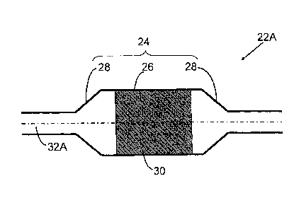
FIG. 1 shows a schematic axially symmetric catalytic converter
FIG. 2 shows a schematic catalytic converter with angled inlet
FIG. 3 shows a schematic catalytic converter with curved inlet
FIG. 4 is a view similar to FIG. 1 showing the points of maximum gas
velocity at
the intersection of the inlet pipe and the can at the lower limit of an
operating power range and the upper limit of an operating power range
3
,
CA 02846642
FIG. 5 is a view similar to FIG. 2 showing the points of maximum gas
velocity at
the intersection of the inlet pipe and the can at the lower limit of the
operating power range and the upper limit of the operating power range;
FIG. 6 is a view similar to FIG. 3 showing the points of maximum gas
velocity at
the intersection of the inlet pipe and the can at the lower limit of the
operating power range and the upper limit of the operating power range;
FIG. 7 shows a schematic catalytic converter similar to FIG. 1;
FIG. 7A is a view along section 7A-7A of FIG. 1;
FIG. 8 shows a schematic catalytic converter similar to FIG. 1;
FIG. 8A is a view along section 8A-8A of FIG. 7;
FIG. 9 shows a schematic catalytic converter similar to FIG. 1;
FIG. 9A is a view along section 9A-9A of FIG. 9;
FIG. 10 shows a schematic catalytic converter similar to FIG. 3;
FIG. 10A is a view along section 10A-10A of FIG. 10;
FIGS. 11A-0 show inlet back pressure as a function of insulation position for
a variety of
catalytic converters of the type shown in FIG. 7.
4
, , ,
" = ' CA 02846642 2014-04-25 __ --" ' __ =
DETAILED DESCRIPTION OF AN EXEMPLARY METHOD
Reference is now made to FIGS. 1-3 which show exemplary catalytic converter
systems
with which the invention can be usefully deployed:
= FIG. 1 shows a schematic axially symmetric catalytic converter system 22A
= FIG. 2 shows a schematic catalytic converter system 22B with angled inlet
= FIG. 3 shows a schematic catalytic converter system 22C with curved inlet
Each system 22A,22B and 22C includes a can 24 having a cylindrical housing 26
and a
pair of diffuser cones 28 and a honeycomb ceramic substrate 30 substantially
fully
occupying the can 24. The can 24 in system 22A is fed by a cylindrical inlet
pipe 32A
aligned with the axis of the can 24; in system 22B, the inlet pipe 32B is
cylindrical but
disposed at angle a to the axis of the can; and in system 22C, the inlet pipe
32C is
curved.
Initial steps in the method involve, in respect of any given engine with which
the
converter is to be used, the determination of the gas direction at the point
of maximum
gas velocity
= when the engine is at the lower limit of the operating power range of
concern;
and
= when the engine is at the upper limit of the operating power range of
concern.
_ _ ..
CA 02846642 2014-04-25
The operating range varies from application to application and in some cases,
the range
may be defined by a single value. For example, stationary engines, such as
generators,
are often used at a single power setting, typically 60 ¨ 80% of designed
power, while
large freight trucks are operated at a highway cruising power level (20 ¨ 30%
of
maximum) for most of their operating time. In the case of common passenger
vehicles,
the operating range used may be that defined by the typical operating power
range, i.e.
something between 30 and 80 percent of the maximum power of the engine. The
determination of gas direction can be done through measurement, but will
normally be
done through Computational Fluid Dynamics (CFD) modelling, as the
interposition of
measurement devices can themselves create flow disruption
In the context of the catalytic converter shown in FIG. 3, there exists a
substantial
difference between the points of maximum gas velocity Vrnax 1, Vmax 2: at
lower gas
velocities the centrifugal force that the gas molecules are exposed to in the
curved pipe
is lower and the maximum of the exhaust gas distribution V.1 is closer to the
center of
the pipe; at higher gas velocities the centrifugal force is stronger and the
maximum of
the exhaust gas distribution Vmax2 is closer to the pipe wall, all as shown in
FIG. 6.
CFD simulations show, that, for a curved inlet pipe 58 mm in diameter, the
difference
between the low and high flow positions is 11 mm.
Similar simulations can be done for the catalytic converters of FIGS. 2 and 3,
as in
some exceptional circumstances, some divergence may occur, but nominally, the
point
of maximum gas velocity, and both high and low flow conditions, is simply
aligned with
the centreline of the inlet pipe in both cases, as shown in FIGS. 4 and 5.,
wherein Vmax
and Vmax i are defined by the same vector.
6
CA 02846642 2014-04-25 - ____________________________
With this information in hand, a benchmark is designed. In the benchmark:
= an outer tubular outer catalytic zone portion of the substrate surrounds
an inner
catalytic zone portion of the substrate;
= an insulation material thermally separates the inner catalytic zone and
the outer
outer catalytic zone;
= an insulation material extends through the substrate and has a uniform
cross-
section throughout the length of the substrate;
= the uniform cross-section is substantially defined by the intersection of
two
notional cylinders and the upstream face of the substrate;
= each notional cylinder has: a nominal inner diameter that is between 1.08
and
1.20 of the diameter of the inlet pipe; a thickness of 0.8-4 mm; and an axis
aligned with the gas direction at the point of maximum velocity at the
intersection
of the inlet pipe and the can; and
= one Ci of the notional cylinders is associated with the gas flow at the
lower limit
of the operating power range and the other C2 of the notional cylinders is
associated with the gas flow at the upper limit of the operating power range
The benchmarks for the exemplary systems of FIGS. 4-6 are shown in FIGS. 7-9;
in
each benchmark, the outer zone is indicated by Z., the inner zone is indicated
by Z1
and the insulation layer is indicated by I.
7
02846642 2014-04-25 .----
It will be evident that, in the converter of FIG. 1, the notional cylinders C1
and C2 will be
coincident and define a cylinder of insulation, as indicated in FIG. 7A; in
the converter of
FIG. 2, the notional cylinders C1 and C2 will be coincident and will define an
ellipse, as
indicated in FIG. 8A; and in the converter of FIG. 6, the notional cylinders
will be
overlapping but not coincident and the insulation is defined by an ovaloid C1
C2 that
overlaps both projections, as indicated in FIG. 9A.
A variation to FIG. 9 is shown in FIG. 10, wherein the inlet pipe is curved
and enters
adjacent the sidewall of the housing. The location causes a portion of the
ovaloid
C1+C2 defined by notional cylinders C1 and C2 to project outside the
cylindrical housing
26, such that only an arc lies within the housing 26. To accommodate this
notional loss
of flow area, the endpoints of the arc are drawn apart from one another, as
indicated by
arrows A in FIG. 10, until such time as the area encompassed between the arc
and the
can sidewall is equivalent to the area of the original ovaloid. The same
adjustment
applies for converters of the type shown in FIG. 8, if the projection lies
outside the can.
Without intending to be bound by theory, it is believed that the benchmark
will expedite
the design of insulated catalytic converter substrates, as this reduce the
routine
experimentation otherwise required of persons of ordinary skill in the art.
Experimentation has been carried out which supports this conclusion. By way of
example, FIGS. 11A-11D show inlet back pressure as a function of insulation
position
for a variety of catalytic converters of the type shown in FIG. 7. FIG. 11A
shows results
for a 26mm radius inlet pipe. FIG. 11B shows results for a 29 mm radius inlet
pipe.
FIG. 11C shows results for a 32 mm radius inlet pipe. FIG. 11D shows results a
35 mm
radius inlet pipe. All other simulation parameters were equal, including
exhaust gas
temperature and flow rate through the catalytic converter.
8
Optimum insulation position was defined as that producing the minimum area
averaged
back pressure in the inlet pipe approx. 30 cm from the catalytic converter
can. In each
case, the optimum insulation diameter fell within the range of 1.08 and 1.20
of the inlet
pipe diameter.
Whereas but a specific embodiment of a method is described, and various
specific
embodiments of catalytic converter substrates are described, it will be
evident that
variations are possible.
For example, whereas the examples contemplate usefulness with cylindrical
inlet pipes,
the methodology would be useful for pipes that departed slightly from the
perfectly
cylindrical; thus, "cylindrical" in the description and in the claims should
be understood
as any pipe that appears generally cylindrical in cross section.
Additionally, whereas the terms "inner" and "outer" are used in the
specification and
claims, it should be understood that in the variation contemplated by FIG. 10,
the "outer"
zone is that portion indicated as lying above insulation I and the "inner"
zone is that
portion indicated as lying below insulation I; "inner" and "outer" are
references to
proximity to the inlet pipe axis.
Accordingly, the invention should be understood as limited only by the
accompanying
claims, purposively construed.
9