Note : Les descriptions sont présentées dans la langue officielle dans laquelle elles ont été soumises.
.1 = A
81778790
1
REVERSE CIRCULATION BIT ASSEMBLY
PRIORITY CLAIM
[0001] This application claims the benefit of and priority
from U.S. Provisional
Patent Application No. 61/548,037 filed on October 17, 2011.
FIELD
10002] The present application relates to drill bits used
for earth boring, such as
water wells; oil and gas wells; injection wells; geothermal wells; monitoring
wells,
mining; and, other operations in which a well-bore is drilled into the Earth.
BACKGROUND
100031 Specialized drill bits are used to drill well-bores,
boreholes, or wells in
the earth for a variety of purposes, including water wells; oil and gas wells;
injection
wells; geothermal wells; monitoring wells, mining; and, other similar
operations.
These drill bits come in two common types, roller cone drill bits and fixed
cutter
drill bits.
[0004] Wells and other holes in the earth are drilled by
attaching or connecting a
drill bit to some means of turning the drill bit. In some instances, such as
in some
mining applications, the drill bit is attached directly to a shaft that is
turned by a
motor, engine, drive, or other means of providing torque to rotate the drill
bit.
100051 In other applications, such as oil and gas drilling, the well may be
several
thousand feet or more in total depth. In these circumstances, the drill bit is
connected to the surface of the earth by what is referred to as a drill string
and a
motor or drive that rotates the drill bit. The drill string typically
comprises several
elements that may include a special down-hole motor configured to provide
additional or, if a surface motor or drive is not provided, the only means of
turning
CA 2855717 2019-02-28
CA 02855717 2014-04-15
WO 2013/059344
PCT/US2012/060647
2
the drill bit. Special logging and directional tools to measure various
physical
characteristics of the geological formation being drilled and to measure the
location
of the drill bit and drill string may be employed. Additional drill collars,
heavy,
thick-walled pipe, typically provide weight that is used to push the drill bit
into the
formation being drilled. Finally, drill pipe connects these elements, the
drill bit,
down-hole motor, logging tools, and drill collars, to the surface where a
motor or
drive mechanism turns the entire drill string and, consequently, the drill
bit, to
engage the drill bit with the geological formation to drill the well-bore
deeper.
[0006] A standard roller cone drill bit 202 is shown in FIG. 3. In FIG.
3, the
roller cone drill bit 202 is comprised of a body 300 having a shank 302 and a
plurality of legs 304. Although not shown in FIG. 3, the shank 302 has an
external
thread for connection to an adjacent drill string component. A bore 310
extends
from the shank 302 through the body 300 of the roller cone bit 202. The legs
304
extend towards the front of the roller cone bit 202 and have a roller cone 306
disposed at an end of the leg 304. Although not illustrated, each roller cone
306 has
at least one cutter disposed on an external surface of the roller cone 306 for
degrading a formation. The cutters may be formed of a hardened material or
have a
coating of a hard material such as polycrystalline diamond. The roller cones
306
have a central axis about which they rotate, with the roller cone 306 being
rotatably
connected to the leg 304.
[0007] As a bore hole is drilled, fluid, typically a water or oil based
drilling fluid
referred to as drilling mud, is pumped down the drill string through the drill
pipe and
any other elements present and through the drill bit. Other types of drilling
fluids
are sometimes used; including air, nitrogen, foams, mists, and other
combinations of
gases, fluids, and mixtures of gases and fluids, but for purposes of this
application,
CA 02855717 2014-04-15
WO 2013/059344
PCT/US2012/060647
3
drilling fluid and/or drilling mud refers to any type of drilling fluid,
including gases,
fluid, and combinations thereof. In other words, drill bits typically have a
fluid
channel within the drill bit to allow the drilling mud to pass through the bit
and out
one or more jets, ports, or nozzles. The purpose of the drilling fluid is to
cool and
lubricate the drill bit, to stabilize the well-bore from collapsing, to
prevent fluids
present in the geological formation from entering the well-bore, and to cany
fragments or cuttings removed by the drill bit up thc annulus and out of the
well-
bore.
[0008] In a standard roller cone bit, drilling fluid is pumped to a
working face
308 of the roller cone bit 202 through the drill string to the roller cone
drill bit 202.
The fluid flows through the bore 310 of the roller cone drill bit 202 to the
roller
cones 306 and around the roller cone bit 202. The drilling fluid returns up an
annulus (the space between the exterior of the drill pipe and the wall of the
well-
bore). As the drilling fluid flows from the working face 308 to the outside of
the
roller cone bit 202, the drilling fluid carries cuttings from the formation
away from
the roller cone bit 202.
[0009] It may be beneficial in some situations to reverse the
circulation of the
drilling fluid. In such situations the drilling fluid is pumped down the
annulus of the
well-bore, across the face of the drill bit, and into the inner fluid channels
of the drill
bit through and up into the interior of the drill string. Alternatively, the
drill string
may have at least one section of double-wall pipe. Double wall pipe has an
inner
passage defined by an inner surface of the inner wall of the pipe and an outer
passage defined by the outer surface of the inner wall and the inner surface
of the
outer wall. The drilling fluid may then be pumped down the outer passage and
exit
the exterior of the drill string proximate the drill bit. The drilling fluid
then returns
CA 02855717 2014-04-15
WO 2013/059344
PCT/US2012/060647
4
through the inner passage. It is also possible for the fluid to be pumped down
the
inner passage and crossover to the outer passage prior to the drill bit where
the
drilling fluid exits the drill string.
[0010] In either situation, the drilling fluid being pumped down the
annulus or
the drilling fluid being pumped down the outer passage of the double wall
pipe, the
drilling fluid does not necessarily pass across the face of the drill bit.
Often much of
the drilling fluid bypasses the face of the drill bit and flows to the inner
channels of
the drill bit through other paths, such as between the legs in the roller cone
bit. To
direct more of the fluid to the face of the roller cone bit, extensions may be
welded
to the roller cone bit between each of the legs. However, the process of
welding the
extensions may heat the bearings and seals of the roller cones affecting the
longevity
of the drill bit. Thus there is a need for a way to direct more of the fluid
to the face
of an existing roller cone drill bit without detrimentally affecting the
longevity of the
dill bit.
SUMMARY
[0011] Embodiments of the present invention include a drill bit assembly
for
earth boring. The drill bit assembly includes a drill bit and a bit sub. The
drill bit
has a front bit end and a rear bit end. The front bit end has a plurality
cutting
elements at a forward face of the front bit end and a first fluid return
passage
extending through the drill bit to the rear end. The bit sub is disposed about
the rear
bit end and couples to the rear bit end. The bit sub includes a body with a
front sub
end, a rear sub end, and a bore disposed at the front sub end sized and shaped
to
receive the rear bit end of the drill bit. The rear sub end is adapted to
connect to an
adjacent downhole component, such as a drill pipe. A plurality of legs extends
from
a mid sub region toward the front sub end between pairs of cutting elements.
The
81778790
plurality of legs preferably have a fluid delivery passage disposed therein
with the fluid
delivery passage extending from the plurality of legs to the rear sub bit end.
The bit sub has a
second fluid return passage connecting the first fluid return passage to the
rear sub bit end
with the second fluid return passage preferably being isolated from the fluid
delivery passage
5 within the bit sub.
[0012j In another embodiment, a bit sub includes a body, a plurality
of legs, and a
fluid return passage. The body has a front end, a rear end, and a bore
disposed at the front end
sized and shaped to receive a drill bit. The rear end is adapted to connect to
an adjacent
downhole component. The plurality of legs extends from the front end and has a
forward end.
The plurality of legs is adapted to complement an outer surface of the drill
bit. Each of the
plurality of legs has a fluid delivery passage disposed therein with the fluid
delivery passage
extending from the forward end to the rear sub bit end. The fluid return
passage connects to
the bore sized and shaped to receive a drill bit and is isolated from the
fluid delivery passage
within the body.
[0013] In another embodiment, a method of fabricating a reverse circulation
drill bit
assembly from a standard drill bit includes providing a standard drill bit and
a bit sub
component. The standard drill bit includes a shank and the bit sub component
has a plurality
of legs extending from a front end of the bit sub component. The shank is
inserted into bit sub
component such that the plurality of legs extends past the shank to a working
surface of the
.. drill bit. The bit sub component is then secured to the drill bit.
10013a1 According to one aspect of the present invention, there is
provided a drill bit
assembly for earth boring, the drill bit assembly comprising: a drill bit
having a front bit end
and a rear bit end, the front bit end having a plurality of cutting elements
at a forward face of
the drill bit, and a first fluid return passage extending through the drill
bit from the front bit
.. end to the rear bit end; a bit sub disposed about the rear bit end and
coupled to the rear bit end,
the bit sub comprising: a nut component having a first end with a bore sized
and shaped to
receive the rear bit end of the drill bit in a threaded connection, a second
end adapted to
CA 2855717 2019-01-23
=
81778790
5a
connect to an adjacent downhole component, and a second fluid return passage
connecting the
first fluid return passage to the second end; and a skirt component disposed
between the nut
component and the drill bit, the skirt component having a central bore sized
and shaped to fit
over a portion of the rear bit end and a plurality of legs extending from the
skirt component
toward the front bit end between pairs of cutting elements.
10013b] According to another aspect of the present invention, there is
provided a bit sub
component comprising: a body with a front bit sub end, a rear bit sub end, and
a bore disposed
at the front bit sub end sized and shaped to receive a drill bit, the rear bit
sub end adapted to
connect to an adjacent downhole component; a plurality of legs extending from
the front bit
sub end toward a forward end, the plurality of legs adapted to complement an
outer surface of
the drill bit, and having a fluid delivery passage disposed therein, the fluid
delivery passage
extending from the forward end to the rear bit sub end: and a fluid return
passage connecting
the bore sized and shaped to receive the drill bit, the fluid return passage
being isolated from
the fluid delivery passage.
10013c1 According to still another aspect of the present invention, there
is provided a
- method of fabricating a reverse circulation drill bit assembly from a drill
bit, the method
comprising: providing a drill bit having a shank; providing a bit sub
component comprising a
nut component and a skirt component having a plurality of legs extending from
the skirt
component; inserting the shank through the skirt component and into nut
component such that
the plurality of legs extends past the shank to a working surface of the drill
bit; and rotating
the nut component relative to the shank to secure the drill bit through a
threaded connection to
the nut component with the plurality of legs extending past the shank to the
working surface
of the drill bit.
[0013d] According to another aspect of the present invention, there is
provided a drill
bit assembly for earth boring, the drill bit assembly comprising: a drill bit
having a front bit
end and a rear bit end, the front bit end having a plurality of cutting
elements at a forward face
of the drill bit, and a first fluid return passage extending through the drill
bit from the front bit
end to the rear bit end; a bit sub disposed about the rear bit end and coupled
to the rear bit end,
CA 2855717 2019-01-23
=
81778790
5b
the bit sub comprising: a body with a front bit sub end, a rear bit sub end,
and a bore disposed
at the front bit sub end sized and shaped to receive the rear bit end of the
drill bit, the rear bit
sub end adapted to connect to an adjacent downhole component; a plurality of
legs extending
from front bit sub end toward the front bit end between pairs of cutting
elements; and a second
fluid return passage connecting the first fluid return passage to the rear bit
sub end; wherein
the plurality of legs have a fluid delivery passage disposed therein, the
fluid delivery passage
extending from the plurality of legs to the rear bit sub end, wherein the
fluid delivery passage
is separated from the second fluid return passage.
[0013e] According to another aspect of the present invention, there is
provided a
method of fabricating a reverse circulation drill bit assembly from a standard
drill bit, the
method comprising: providing an existing drill bit having a shank; providing a
bit sub
component having a plurality of legs extending from a front bit sub end of the
bit sub
component; inserting the shank into the bit sub component such that the
plurality of legs
extends past the shank to a working surface of the existing drill bit; and
securing the bit sub
component to the standard drill bit; wherein the bit sub component is
comprised of a skirt
having the plurality of legs and a body section, wherein the method further
comprises placing
the skirt over the shank such that the shank extends through the skirt and the
shank is coupled
to the body section through a threaded connection; and wherein the body
section is comprised
of a nut section and a check valve section, the method further comprising
coupling the nut
section to the check valve section.
BRIEF DESCRIPTION OF THE DRAWINGS
[00141 To further clarify the above and other advantages and features
of the one or
more present inventions, reference to specific embodiments thereof are
illustrated
CA 2855717 2019-01-23
CA 02855717 2014-04-15
WO 2013/059344
PCT/US2012/060647
6
in the appended drawings. The drawings depict only typical embodiments and are
therefore not to be considered limiting. One or more embodiments will be
described
and explained with additional specificity and detail through the use of the
accompanying drawings in which:
[0015] FIG. 1 illustrates a schematic of a cross-section of a bore hole
having a
drill string compatible with embodiments of the present invention.
[0016] FIG. 2 illustrates a rcversc flow bit assembly in accordance with
an
embodiment of the current invention.
[0017] FIG. 3 illustrates a cross section of a three cone roller cone
bit used in
reverse flow bit assembly of FIG 2.
[0018] FIG. 4 illustrates a cross section of a skirt section used in the
reverse
flow bit assembly of FIG. 2.
[0019] FIG. 5 illustrates a cross section of the nut section used in the
reverse
flow bit assembly of FIG. 2.
[0020] FIG. 6 illustrates a cross section of a check valve section used in
the
reverse flow bit assembly of FIG. 2.
[0021] FIG. 7 illustrates a cross section of the reverse circulation
drill bit
assembly of FIG. 2 showing the flow of drilling fluid.
[0022] FIG. 8 illustrates a reverse flow bit assembly in accordance with
an
embodiment of the current invention.
[0023] FIG. 9 illustrates a cross section of a skirt section used in the
reverse flow
bit assembly of FIG. 8.
[0024] FIG. 10 illustrates a cross section of the nut section used in
the reverse
flow bit assembly of FIG. 8.
CA 02855717 2014-04-15
WO 2013/059344
PCT/US2012/060647
7
[0025] FIG. 11 illustrates a cross section of the reverse circulation
drill bit
assembly of FIG. 8 showing the flow of drilling fluid.
[0026] The drawings are not necessarily to scale.
DETAILED DESCRIPTION
[0027] As used herein, "at least one," "one or more," and "and/or" are open-
ended expressions that are both conjunctive and disjunctive in operation. For
example, each of the expressions "at least one of A, B and C," "at least one
of A, B,
or C," "one or more of A, B, and C," "one or more of A, B, or C" and "A, B,
and/or
C" means A alone, B alone, C alone, A and B together, A and C together, B and
C
together, or A, B and C together.
[0028] Various embodiments of the present inventions are set forth in
the
attached figures and in the Detailed Description as provided herein and as
embodied
by the claims. It should be understood, however, that this Summary does not
contain
all of the aspects and embodiments of the one or more present inventions, is
not
meant to be limiting or restrictive in any manner, and that the invention(s)
as
disclosed herein is/are and will be understood by those of ordinary skill in
the art to
encompass obvious improvements and modifications thereto.
[0029] Additional advantages of the present invention will become
readily
apparent from the following discussion, particularly when taken together with
the
accompanying drawings.
[0030] FIG. 1 illustrates a schematic of a cross-section of a borehole
100 having
a drill string 102 disposed therein. A derrick 104 connects the drill string
102 to the
top surface of an earthen formation 106. The drill string 102 is comprised of
a
plurality of down-hole tool components, such as pipe segments, measuring
tools,
and drill bits. The pipe segments have an inner bore providing a passageway
for
CA 02855717 2014-04-15
WO 2013/059344
PCT/US2012/060647
8
fluid to be transferred through the drill string. The pipe segments may be
double
walled providing two separate passages for fluid. An annulus 108 is formed
between the drill string 102 and an inner wall of the borehole 100. A drill
bit 110
disposed at the bottom of the drill string 102. Movement of the drill bit 110
degrades the formation 106 allowing the drill string 102 to proceed further
into the
formation 106.
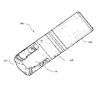
[0031] FIG. 2 illustrates an embodiment of a reverse circulation bit
assembly
200. The reverse circulation drill bit assembly 200 is generally comprised of
a roller
cone bit 202 and a skirt 204. The reverse circulation bit assembly 200 further
comprises a nut section 206 and a check valve section 208. In the embodiment
of
FIG. 2 the skirt 204, the nut section 206, and the check valve section 208 are
shown
as three distinct parts, but in some embodiments they may be combined with one
another so as to have less than three distinct components. The skirt 204, the
nut
section 206, and the check valve section 208 are generally referred to as a
bit sub,
whether they are distinct components or combined. Furthermore, the skirt 204,
the
nut section 206, or the check valve section 208 may each be comprised of
individual
parts making up that component.
[0032] FIG. 3 illustrates the roller cone bit 202 of FIG. 2 in more
detail. The
illustrated roller cone bit 202 is a standard three cone roller cone bit.
However,
other types of bits may be used in the reverse circulation bit assembly 200
and
embodiments are not limited to three cone roller cone bits. The bits may be
off the
shelf parts and modified to become a reverse circulation bit assembly.
[0033] The operation of the roller cone bit of FIG. 3 was previously
described as
a standard circulation drill bit. Using embodiments of the current invention,
the
roller cone bit of FIG. 3 can be used as a reverse circulation drill bit.
Embodiments
CA 02855717 2014-04-15
WO 2013/059344
PCT/US2012/060647
9
of the current invention enable most drill bits to be used as a reverse
circulation drill
bit.
[0034] FIG. 4 illustrates a cross-section of the skirt 204. The skirt
204 enables
the standard roller cone bit 202 to be used as a reverse circulation bit. The
skirt 204
has a plurality of legs 402 that extend towards the working face 308 of the
roller
cone bit 202. Each leg 402 is sized and shaped to fit closely around and
between the
roller cone bit legs 304. In some embodiments, the roller cone bit legs 304
may be
modified to have a profile that is complementary to that of the skirt legs
402, or in
other embodiments the roller cone bit legs 304 may be unmodified and the skirt
legs
402 may have been modified to complement the profile of the roller cone bit
legs
304. In some embodiments, a combination of modifying the roller cone bit legs
304
and the skirt legs 402 may be used.
[0035] At least one skirt leg 402 has a passageway 404 through which
drilling
fluid can be delivered. The passageway 404 exits the skirt leg 402 proximate
the
working face 308 of the roller cone bit 202. Since the drilling fluid is
provided at
the working face 308, the drilling fluid is more likely to flow across the
working
face 308 and then into the bore 310 of the roller cone bit 202, as opposed to
flowing
closer to the roller cone bit legs 304 without the skirt 204.
[0036] The skirt 204 is sized and shaped to slide over the roller cone
bit 202
such that the skirt legs 402 are proximate the roller cones 306. The skirt 204
has a
central bore 406 sized and shaped to complement the outer surface of the bit
body
300. In some embodiments, the skirt 204 may press fit over the bit body 300.
[0037] FIG. 5 illustrates a cross-sectional view of the nut section 206
of the
reverse circulation bit assembly 200. The nut section 206 secures the skirt
204 to
the roller cone bit 202. The nut section 206 includes an internal surface
having an
CA 02855717 2014-04-15
WO 2013/059344
PCT/US2012/060647
internal thread sized and shaped to complement the external thread of the
roller cone
bit shank 302. As the roller cone shank 302 is threaded into internal thread
of the
nut section 206, the nut section 206 advances towards the working face 308 of
the
roller cone bit 202. The skirt 204 is unable to advance past the front of the
roller
5 cone bit 202 and forms a stop for the nut section 206. When a rear
surface of the
skirt 204 contacts a forward surface 504 of the nut section 206, the nut
section 206
can advance no further. The skirt 204 is then constrained from forward
movement
by the roller cone bit 202 and rearward movement by the nut section 206.
[0038] The nut section 206 includes a trough 506 disposed in the forward
10 surface 504. The trough 506 is annular and the forward surface forms an
inner
sealing surface 510 and an outer sealing surface 508 about the trough 506.
When
the rear surface of the skirt 204 and the forward surface 504 of the nut
section 206
contact one another, a seal is formed between the skirt 204 and the nut
section 206
such that the trough 506 forms a front annular passageway. The through bores
404
from the legs 402 of the skirt 204 extend through the back of the skirt 204
such that
the through bores 404 are fluidly connected with the trough 506 forming the
front
annular passageway. As the nut section 206 is threaded onto the roller cone
bit 202
with the skirt 204 in place, the angular position of the nut assembly 206
relative to
the skirt 204 is unimportant, as the through bores 404 will always line up
with the
trough 506 forming the front annular passageway.
[0039] The nut section 206 may have at least one side bore 512 through
which a
set screw or pin can be inserted to secure the nut section 206 to the roller
cone bit
202. A matching side bore can me be machined in the roller cone bit 202 to
receive
the set screw or pin to prevent the roller cone bit 202 from rotating relative
to the nut
section 206. The matching side bore may be machined prior to the nut section
206
CA 02855717 2014-04-15
WO 2013/059344
PCT/US2012/060647
11
being threaded on the roller cone bit 202, or the matching side bore may be
machined after the nut section 206 is threaded on the roller cone bit 202. In
some
embodiments, no matching side bore may be present and the set screw or pin may
press into the shank 302 of the roller cone bit 202. Other means of securing
the nut
section or the entire bit sub to the bit may be employed.
[0040] A rear end 514 of the nut section 206 includes a rear annular
trough 516
and a center protrusion 518. A nut section bore 520 extends from the forward
surface 504 of the nut section 206 to the rear end 514 of the center
protrusion 518.
The nut section bore 520 aligns with the bore 310 of the roller cone bit 204
and
provides a passage for the return of drilling fluid. The rear annular trough
516 and
the front annular trough 506 are connected by at least one through passage
522. The
through passage 522 enables fluid communication between the rear annular
trough
516 and the forward annular trough 506.
[0041] FIG. 6 illustrates a cross-sectional view of the check valve
section 208.
The check valve section 208 is generally cylindrical with an outer diameter
602
similar to that of the nut section 206 and the skirt section 204. The check
valve
section 208 has a central bore 604 that extends from a front face 606 of the
check
valve section 208 to the rear of the check valve section 208. A wall 610 is
formed
between the central bore 604 and an outer surface 608 of the check valve
section
208. Disposed within the wall 610 is at least one check valve passageway 612
providing fluid communication to the front face 606 of the check valve section
208.
The rear of the check valve section 208 has an enlarged bore 614 that extends
from
the rear of the check valve section 208 to about mid-way the length of the
check
valve section 208.
CA 02855717 2014-04-15
WO 2013/059344
PCT/US2012/060647
12
[0042] Disposed within the check valve passageway 612 is a check valve
assembly 616. The check valve assembly 616 inhibits drilling fluid from
flowing up
the check valve passageway 612. Although different types of check valves
assemblies are compatible with the present embodiments, the check valve
assembly
616 of FIG. 6 comprises a seat 618, a biasing member 620, and a piston 622.
The
biasing member 620 biases the piston 622 into the seat 618 forming a seal.
When a
pressure differential across the seal is sufficient to overcome the bias of
the biasing
member 620, the piston 622 moves against the bias, opening the valve.
[0043] The front face 606 of the check valve section 208 is coupled to
the rear
face of the nut section 206. The front face 606 may be coupled by way of a
welded
connection or other connection means. The front face 606 seals to the rear
annular
trough 516 of the nut section 206 forming a rear annular passage. Like the
relation
between the nut assembly 206 and the skirt 202, the angular position of the
nut
section 206 relative to the check valve section 208 is unimportant, as the
check valve
passageway 612 will always line up with the rear annular passageway.
[0044] As shown in FIG. 7, an inner tube flange 700 is disposed within
the
enlarged bore 614. The inner tubular flange 700 may be threaded into the check
valve section 208. The inner tubular flange 700 has an outer surface, an inner
surface, and a wall there between. The inner surface defines an inner tube
flange
bore that aligns with the central bore 604 of the check valve section 208 and
provides fluid communication from the rear end of the check valve section 208
to
the bore 502 of the nut section 206. The outer surface and the enlarged bore
together define an annular passageway fluidly connecting the rear of the check
valve
section 208 and the check valve passageway 612.
CA 02855717 2014-04-15
WO 2013/059344
PCT/US2012/060647
13
[0045] The rear end of the check valve section 208 is adapted to be
connected to
a tool string. The tool string may be a double walled tool string having two
separate
fluid paths. The tool string connects to the rear end of the check valve
section 208
and connects the two separate fluid paths to the annular passageway of the
check
valve section 208 and the central bore of the check valve section 208.
[0046] Although the bit sub was described with relation to the skirt
204, nut
section 206, and check valve section 208, the check valve section 208 may be
combined with the nut section 206. In some embodiments, the check valve
section
208 may not include a check valve assembly 616. For example, in some instances
a
drill operator may not be concerned about back flow and the check valve
assembly
616 may be eliminated. In such instances, it may be simpler to manufacture the
nut
section 206 and the check valve section 208 as a single component.
[0047] The operation of the reverse circulation drill bit will be
explained in
relation to FTG. 7, which is a cross section of the assembled reverse
circulation drill
bit assembly 200. Drilling fluid is delivered to the annular passageway
fluidly
connecting the rear of the check valve section 208 and the check valve
passageway
612. The pressure of the drilling fluid generates a pressure differential
across the
check valve assembly 616, causing the check valve assembly 616 to open. The
drilling fluid flows from the check valve passageway 612 into the annular
passageway formed by the rear annular trough 516. The drilling fluid then
flows
from the rear annular trough 516 through the through passage 522 into the
forward
annular trough 506. The forward annular trough 506 is in fluid communication
with
the skirt leg passage way 404 and the drilling fluid flows into the skirt leg
passageway 404.
CA 02855717 2014-04-15
WO 2013/059344
PCT/US2012/060647
14
[0048] From the skirt leg passageway 404, the drilling fluid is
delivered to the
working face 308 of the roller cone bit 202. The drilling fluid collects
cuttings and
other material and flows into the bore 310 of the roller cone bit 302. The
bore 310
of the roller cone bit 202 is in fluid communication with the inner tube
flange bore
through the nut section bore 502 and the check valve section bore 604. The
drilling
fluid flows up the reverse flow bit assembly 200 and out of the inner tube
flange
bore.
[0049] FIG. 8 illustrates another embodiment of a reverse circulation
drill bit
assembly 800. The reverse circulation drill bit assembly 800 comprises a
roller cone
bit 202, a skirt section 804, and a nut section 806. In this embodiment, the
drilling
fluid is delivered to the annulus between the drill bit and the bore wall and
not
through the skirt as described in the previous embodiment.
[0050] FIG. 9 illustrates a cross-section of the skirt section 804 of
the reverse
circulation drill bit assembly 800. The skirt section has a plurality of legs
902
extending toward the working face 308 of the roller cone bit 202. Each leg 902
is
sized and shaped to fit closely around and between the roller cone bit legs
304. In
some embodiments, the roller cone bit legs 304 may be modified to have a
profile
that is complementary to that of the skirt legs 902, or in other embodiments
the
roller cone bit legs 304 may be unmodified and the skirt legs 902 may have
been
modified to complement the profile of the roller cone bit legs 304. In some
embodiments, a combination of modifying the roller cone bit legs 304 and the
skirt
legs 902 may be used.
[0051] Unlike the previous embodiment, the skirt legs 902 do not have a
passageway for the delivery of drilling fluid. Instead drilling fluid is
delivered to the
annulus of the drill bit and the skirt legs 902 inhibit the drilling fluid
from flowing
CA 02855717 2014-04-15
WO 2013/059344
PCT/US2012/060647
into the bore 310 of the roller cone bit 202 between the roller cone bit legs
304.
Since the drilling fluid is inhibited from flowing into the bore until 310 it
reaches the
working face 308, the drilling fluid is more likely to flow across the working
face
308 and into the bore 310 of the roller cone bit 202, as opposed to between
the roller
5 cone bit legs 304 without the skirt legs 902.
[0052] The skirt 804 is sized and shaped to slide over the roller cone
bit 202
such that the skirt legs 902 arc proximate the roller cones 306. The skirt 804
has a
central bore 906 sized and shaped to complement the outer surface of the bit
body
300. In some embodiments, the skirt 804 may press fit over the bit body 300.
10 [0053] FIG. 10 illustrates a cross-sectional view of the nut section
806 of the
reverse circulation bit assembly 800. The nut section 806 secures the skirt
804 to
the roller cone bit 202 and provides a means for connecting the reverse
circulation
bit assembly 800 to the drill string. The nut section 806 includes an internal
surface
908 having an internal thread sized and shaped to complement the external
thread of
15 the roller cone bit shank 302. As the roller cone shank 302 is threaded
into internal
thread of the nut section 806, the nut section 806 advances towards the
working face
308 of the roller cone bit 202. The skirt 804 is unable to advance past the
front of
the roller cone bit 202 and forms a stop for the nut section 806. When a rear
surface
of the skirt 804 contacts a forward surface 910 of the nut section 806, the
nut section
806 can advance no further. The skirt 804 is then constrained from forward
movement by the roller cone bit 202 and rearward movement by the nut section
806.
[0054] The nut section 806 includes a shank 910 adapted to connect to a
drill
string. The shank 910 may have an external thread (not shown) for threading
into a
drill string. An internal bore 912 aligns with the bore 310 of the roller cone
bit 202
and allows fluid to flow from the bore 310 of the roller cone bit 202 to a
drill string
CA 02855717 2014-04-15
WO 2013/059344
PCT/US2012/060647
16
bore. The nut section 806 may include a side bore 914 that may receive a set
screw
or pin that can be inserted to secure the nut section 806 to the roller cone
bit 202. A
matching side bore can be machined in the roller cone bit 202 to receive the
set
screw or pin to prevent the roller cone bit 202 from rotating relative to the
nut
section 806. The matching side bore may be machined prior to the nut section
806
being threaded on the roller cone bit 202, or the matching side bore may be
machined after the nut section 806 is threaded on the roller cone bit 202. In
some
embodiments, no matching side bore may be present and the set screw or pin may
press into the shank 302 of the roller cone bit 202. Other means of securing
the nut
section or the entire bit sub to the bit may be employed.
[0055] FIG. 11 illustrates a cross section of the reverse circulation
drill bit
assembly 800 and will be used to describe the reverse circulation of the
drilling
fluid. The direction of the flow of fluid is represented by the arrows on the
figure.
The drill fluid initially is delivered to the annulus 1202 and flows around
the roller
cone drill bit 202. Near the working face 308 the fluid is inhibited from
flowing
between the roller cone legs 304 by the skirt legs 902. The drilling fluid
flow across
the working face 308 and into the central bore 310 of the roller cone drill
bit 202.
The drilling fluid flows from the central bore 310 to the bore 912 of the nut
section
904. From there the drilling fluid flows into the bore of the drill string.
[0056] The forgoing reverse flow bit assemblies 200, 800 can be
manufactured
using a standard, off the shelf drill bit. Embodiments of the invention
include a
method of making a reverse flow circulation bit assembly.
[0057] The method includes providing a standard drill bit. The standard
drill bit
may be a roller cone bit as previously described, or it may include a fixed
blade bit
or any other type of drill bit. A skirt sized and shaped to complement the
drill bit is
CA 02855717 2014-04-15
WO 2013/059344
PCT/US2012/060647
17
provided. In some embodiments the standard drill bit may be modified to
complement the size and shape of the skirt or the skirt may be modified to
complement the size and shape of the standard drill bit. The skirt is placed
over the
shank of the drill bit.
[0058] A nut assembly is then provided and coupled to the standard drill
bit. In
some embodiments the nut assembly may have a female thread that complements
the shank of the standard drill bit. In such embodiments the nut assembly is
threaded onto the shank until the nut assembly contacts the skirt, securing
the skirt in
place. A set screw or pin may then be inserted into the nut assembly to hold
the drill
bit in place. After the nut is in place, a check valve section may then be
coupled to
the nut assembly. Such a coupling may be performed by welding, a threaded
connection, or some other means of connection. In other embodiments, the check
valve section may be coupled to the nut section prior to the nut section being
coupled to the standard drill bit. In some embodiments, the check valve
section and
the nut may be single components that are coupled to the standard drill bit.
[0059] An inner tube flange is provided and coupled to the rear end of
the check
valve section. The inner tube flange may be coupled to the rear end of the
check
valve section prior to the check valve section being coupled to the nut
section, or it
may be coupled after. In some embodiments the inner tube flange is an integral
part
of the check valve section and is not removable.
[0060] The inner tube flange may be sized and shaped for connection to a
specific type of drill string. For example, different inner tube flanges may
be used to
connect the reverse circulation bit assembly with different drill pipes. In
this way a
single reverse circulation drill bit assembly may be compatible with multiple
types
of drill pipe.
CA 02855717 2014-04-15
WO 2013/059344
PCT/US2012/060647
18
[0061] The foregoing discussion of the invention has been presented for
purposes of illustration and description. The foregoing is not intended to
limit the
invention to the form or forms disclosed herein. In the foregoing Detailed
Description for example, various features of the invention are grouped
together in
one or more embodiments for the purpose of streamlining the disclosure. This
method of disclosure is not to be interpreted as reflecting an intention that
the
claimed invention requires more features than arc expressly recited in cach
claim.
Rather, as the following claims reflect, inventive aspects lie in less than
all features
of a single foregoing disclosed embodiment. Thus, the following claims are
hereby
incorporated into this Detailed Description, with each claim standing on its
own as a
separate preferred embodiment of the invention.
[0062] Moreover, though the description of the invention has included
description of one or more embodiments and certain variations and
modifications,
other variations and modifications are within the scope of the invention,
e.g., as may
be within the skill and knowledge of those in the art, after understanding the
present
disclosure. It is intended to obtain rights which include alternative
embodiments to
the extent permitted, including alternate, interchangeable and/or equivalent
structures, functions, ranges or steps to those claimed, whether or not such
alternate,
interchangeable and/or equivalent structures, functions, ranges or steps are
disclosed
herein, and without intending to publicly dedicate any patentable subject
matter.