Note : Les descriptions sont présentées dans la langue officielle dans laquelle elles ont été soumises.
CA 02859763 2014-09-26
253945
BLEED AIR AND HOT SECTION COMPONENT COOLING
AIR SYSTEM OF A GAS TURBINE AND METHOD
BACKGROUND
[0002] The subject matter disclosed herein relates generally to gas turbine
engines
and, more particularly, to bleed air and hot section component cooling air
systems for
gas turbine engines and methods of operating bleed air and hot section
component
cooling air systems.
[0003] Some gas turbine engines include an air flow path through a low
pressure
compressor, a high pressure compressor, a combustor, a high pressure turbine,
and a
low pressure turbine. Some gas turbine engines may be configured to withdraw
compressed air from the high pressure compressor and provide the compressed
air for
use in various aircraft and/or engine systems. As used herein, compressed air
taken
from a compressor of a gas turbine engine may be referred to as "bleed air."
[0004] In some gas turbine engines, the temperature of the gas stream exiting
the
combustor may be above about 1500 degrees C. To prevent undesired thermal
effects
on turbine components due to exposure to the high-temperature gas stream, some
components of the turbine may be cooled. For example, bleed air may be
supplied to
one or more hot section components (e.g., high pressure turbine blades) for
cooling.
As used herein, bleed air used for hot section component cooling may be
referred to
as "hot section component cooling air."
[0005] The problem: Withdrawing bleed air from a compressor of a gas turbine
engine may reduce the efficiency of the gas turbine engine.
BRIEF DESCRIPTION OF THE INVENTION
[0006] The solution for the above-mentioned problem is provided by example
embodiments of the present disclosure.
[0007] Some example combined bleed air and hot section component cooling air
systems for gas turbine engines according to at least some aspects of the
present
1
CA 02859763 2014-06-18
WO 2013/126122
PCT/US2012/068327
disclosure may include a high-pressure bleed air line configured to receive
high-
pressure bleed air from a high-pressure stage of a compressor; a first
precooler
operatively connected to the high-pressure bleed air line to receive at least
some of the
high-pressure bleed air, transfer heat from the high-pressure bleed air to
ambient air,
and discharge cooled high-pressure bleed air; a high-pressure discharge line
operatively connected to the first precooler to receive the cooled high-
pressure bleed
air; a first pressure regulator in the high-pressure discharge line, the first
pressure
regulator being configured to receive at least some of the cooled high-
pressure bleed
air and discharge pressure-regulated cooled bleed air; a pneumatic systems
supply line
operatively connected to the high-pressure discharge line downstream of the
first
pressure regulator to receive the pressure-regulated cooled bleed air; and/or
a hot
section component cooling air line operatively connected to the high-pressure
discharge line upstream of the first pressure regulator and configured to
convey at
least some of the cooled high-pressure bleed air to a hot section component
for use as
hot section component cooling air.
[0008] Some example combined bleed air and hot section component cooling air
systems for gas turbine engines according to at least some aspects of the
present
disclosure may include a high-pressure bleed air line configured to receive
high-
pressure bleed air from a high-pressure stage of a compressor; a first
precooler
operatively connected to the high-pressure bleed air line, the first precooler
being
configured to receive at least some of the high-pressure bleed air, transfer
heat from
the high-pressure bleed air to ambient air, and discharge cooled high-pressure
bleed
air; a high-pressure discharge line operatively connected to the first
precooler to
receive the cooled high-pressure bleed air; an intermediate-pressure bleed air
line
configured to receive intermediate-pressure bleed air from an intermediate
stage of
the compressor; a second precooler operatively connected to the intermediate-
pressure
bleed air line, the second precooler being configured to receive the
intermediate-
pressure bleed air, transfer heat from the intermediate-pressure bleed air to
the
ambient air, and discharge cooled intermediate-pressure bleed air; an
intermediate-
pressure discharge line operatively connected to the second precooler to
receive the
cooled intermediate-pressure bleed air; a first pressure regulator operatively
connected to at least one of the high-pressure discharge line and the
intermediate-
2
CA 02859763 2014-06-18
WO 2013/126122
PCT/US2012/068327
pressure discharge line, the first pressure regulator being operative to
discharge
pressure-regulated cooled bleed air; and/or a pneumatic systems supply line
operatively connected to the first pressure regulator to receive the pressure-
regulated
cooled bleed air; a hot section component cooling air line operatively
connected to the
high-pressure discharge line upstream of the pressure regulator and configured
to
convey at least some of the cooled high-pressure bleed air to a hot section
component
for use as hot section component cooling air.
[0009] Some example methods of operating a combined bleed air and hot section
component cooling air system according to at least some aspects of the present
disclosure may include withdrawing high-pressure air from a high-pressure
stage of a
compressor of a gas turbine engine via a high-pressure bleed air line; cooling
at least a
first portion of the high-pressure air using a precooler operatively connected
to the
high-pressure bleed air line to provide cooled high-pressure air via a high-
pressure
discharge line; supplying a first portion of the cooled high-pressure air to a
hot section
component of the gas turbine engine for use as hot section component cooling
air via
a hot section component cooling air line operatively connected to the high-
pressure
discharge line; supplying a second portion of the cooled high-pressure air to
a
pressure regulator via the high-pressure discharge line, the pressure
regulator
providing pressure-regulated cooled air to a pneumatic systems supply line;
and/or
supplying the pressure-regulated cooled air to at least one pneumatic system
via the
pneumatic systems supply line.
[0010] The foregoing brief description is illustrative only and is not
intended to be
in any way limiting. In addition to the illustrative aspects, embodiments, and
features
described above, further aspects, embodiments, and features will become
apparent by
reference to the drawings and the following detailed description.
BRIEF DESCRIPTION OF THE DRAWINGS
[0011] Example embodiments are described herein with reference to the
drawings,
in which:
FIG. 1 is a block diagram of an example combined bleed air and hot section
component cooling air system;
FIG. 2A is a perspective view of an example two-compartment precooler;
3
CA 02859763 2014-06-18
253945
FIG. 2B is a perspective view of an alternative example two-compartment
precooler;
FIG. 3 is a block diagram of an alternative example combined bleed air and
hot section component cooling air system;
FIG. 4 is a block diagram of an alternative example combined bleed air and
hot section component cooling air system;
FIG. 5 is a block diagram of an alternative example combined bleed air and
hot section component cooling air system; and
FIG. 6 is a flowchart illustrating an example method of operating a combined
bleed air and hot section component cooling air system; all in accordance with
at least
some aspects of the present disclosure.
DETAILED DESCRIPTION
[0012] In the following detailed description, reference is made to the
accompanying
drawings, which form a part hereof. In the drawings, similar symbols typically
identify similar components, unless context dictates otherwise. The
illustrative
embodiments described in the detailed description, drawings, and claims are
not
meant to be limiting. Other embodiments may be utilized, and other changes may
be
made, without departing from the scope of the subject matter presented here.
It will
be readily understood that the aspects of the present disclosure, as generally
described
herein, and illustrated in the figures, can be arranged, substituted,
combined, and
designed in a wide variety of different configurations, all of which are
explicitly
contemplated and make part of this disclosure.
[0013] The present disclosure includes, inter alia, combined bleed air systems
and
hot section component cooling air systems associated with gas turbine engines
and
methods of operating combined bleed air and hot section component cooling air
systems.
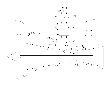
[0014] FIG. 1 is a block diagram of an example gas turbine engine 10,
according to
at least some aspects of the present disclosure. Engine 10 may be configured
to flow
air through a fan 102, a low-pressure compressor 104, a high-pressure
compressor
106, a combustor 108, a high-pressure turbine 110, and/or a low-pressure
turbine 112.
Engine 10 may include a combined bleed air and hot section component cooling
air
4
CA 02859763 2014-06-18
WO 2013/126122
PCT/US2012/068327
system 100, which may be configured to provide bleed air (e.g., compressed air
taken
from low-pressure compressor 104 and/or high-pressure compressor 106) to one
or
more pneumatic systems 114, such as an aircraft environmental control system
(ECS).
Other example pneumatic systems which may utilize bleed air include, without
limitation, wing anti-icing systems, engine cowl anti-icing systems, pneumatic
actuators, and engine starting systems.
[0015] Bleed air may be taken from one or more stages of low-pressure
compressor
104 and/or high-pressure compressor 106. For example, intermediate-pressure
bleed
air may be taken from an intermediate stage (e.g., via an intermediate-
pressure bleed
air line 116, which may be connected to an extraction port 117 approximate a
fourth
stage of high-pressure compressor 106) and/or high-pressure bleed air may be
taken
from a high-pressure stage (e.g., via a high-pressure bleed air line 118,
which may be
connected to an extraction port 119 approximate a seventh stage of high-
pressure
compressors 106) of high-pressure compressor 106. In some example embodiments
in which extraction port 119 is disposed approximate a final stage of high-
pressure
compressor 106, high-pressure bleed air line 118 may receive bleed air at
about
compressor discharge pressure.
[0016] Intermediate-pressure bleed air line 116 and/or high-pressure bleed air
line
118 may direct bleed air to a precooler 120. Intermediate-pressure bleed air
line 116
and/or high-pressure bleed air line 118 may include one or more valves between
high-
pressure compressor 106 and precooler 120. For example, intermediate-pressure
bleed air line 116 may include a check valve 122, which may be arranged to
allow air
flow from high-pressure turbine 106 to precooler 120 while substantially
preventing
air flow from precooler 120 to high-pressure turbine 106. High-pressure bleed
air line
118 may include an isolation valve 124, which may be selectively operable to
allow
and substantially prevent air flow from high-pressure compressor 106 to
precooler
120.
[0017] As described below in connection with FIGS. 2A and 2B, precooler 120
may
comprise a heat exchanger configured to transfer heat from the bleed air to
ambient
air 206, which may be supplied from fan 102. For example, precooler 120 may be
configured to cool the bleed air to less than about 230 degrees C by
transferring heat
to cooling stream air, such as, but not limited to, ambient, fan, or bypass
streams. For
CA 02859763 2014-06-18
WO 2013/126122
PCT/US2012/068327
example, precooler 120 may transfer heat to ambient air 206, which may be
supplied
via fan 102 as a fan stream. Some example embodiments may include a fan air
valve
207, which may be arranged to allow, prevent, and/or regulate ambient air 206
supplied from fan 102. Precooler 120 may be configured to discharge cooled
intermediate-pressure bleed air via an intermediate-pressure discharge line
132 and/or
precooler 120 may be configured to discharge cooled high-pressure bleed air
via a
high-pressure discharge line 134. In some example embodiments, a position
(e.g.,
open-shut) of fan air valve 207 may be controlled at least in part based upon
a
temperature of cooled intermediate-pressure bleed air in intermediate-pressure
discharge line 132 and/or a temperature of cooled high-pressure bleed air in
high-
pressure discharge line 134. Some example embodiments may include separate
precoolers operatively coupled to intermediate-pressure bleed air line 116 and
high-
pressure bleed air line 118. Such embodiments may be configured in a parallel
or
series flow arrangements from the perspective of ambient air 206.
[0018] Intermediate-pressure discharge line 132 may supply pressure-regulated
cooled bleed air to pneumatic systems 114 via one or more pressure-regulators,
such
as pressure-regulating shut-off valve 126. High-pressure discharge line 134
may
supply pressure-regulated cooled bleed air to pneumatic systems 114 via one or
more
pressure-regulators, such as a pressure-regulating shut-off valve 128. In some
example embodiments, pressure-regulating shut-off valve 126 and/or pressure-
regulating shut-off valve 128 may be configured to supply pressure-regulated
cooled
bleed air to pneumatic systems 114 at about 30 psig to about 40 psig (about
207 kPa
to about 276 kPa) via pneumatic systems supply line 127.
[0019] Some example combined bleed air and hot section component cooling air
systems 100 may be configured to supply hot section component cooling air to
one or
more hot section components, such as high-pressure turbine 110, for cooling.
For
example, hot section component cooling air may be supplied to turbine blades
and/or
vanes for cooling. Hot section component cooling air may be supplied from high-
pressure compressor 106 to high-pressure turbine 110 via high-pressure bleed
air line
118, valve 124, precooler 120, high-pressure discharge line 134, and a hot
section
component cooling air line 130, which may be connected to high-pressure
discharge
line 134. Because hot section component cooling air line 130 may receive
cooled
6
CA 02859763 2014-06-18
WO 2013/126122
PCT/US2012/068327
high-pressure bleed air that has flowed through precooler 120, hot section
component
cooling air line 130 may supply hot section component cooling air to high-
pressure
turbine 110 at a temperature lower than the temperature of high-pressure bleed
air
taken from high-pressure compressor 106 by high-pressure bleed air line 118.
[0020] Some example combined bleed air and hot section component cooling air
systems 100 may be configured to supply hot section component cooling air to
high-
pressure turbine 110 from high-pressure compressor 106 without flowing the hot
section component cooling air through precooler 120. For example, some
combined
bleed air and hot section component cooling air systems 100 may include a
bypass
line 136, which may include a bypass line valve 138. If it is desired to
supply some or
all hot section component cooling air directly from high pressure compressor
106,
bypass line valve 138 may be partially or fully opened. If it is desired to
supply some
or all hot section component cooling air via precooler 120, valve 124 may be
partially
or fully opened. In some example embodiments, valve 124 and/or bypass line
valve
138 may be throttled to achieve a desired flow rate therethrough. Some example
embodiments may not include valve 124, bypass line 136, and/or bypass line
valve
138. Some example embodiments may be configured to supply hot section cooling
air comprising both cooled air (e.g., via hot section component cooling air
line 130)
and uncooled air (e.g., via bypass line 136), such as by at least partially
opening both
valve 124 and bypass line valve 138.
[0021] FIG. 2A is a perspective view of an example two-compartment precooler
120, according to at least some aspects of the present disclosure. It is
within the scope
of this disclosure to use any known suitable heat exchanger, such as one or
more
known precoolers. Precooler 120 may include a first compartment 202 configured
to
receive air from intermediate-pressure bleed air line 116 and discharge air to
intermediate-pressure discharge line 132. Precooler 120 may include a second
compartment 204 configured to receive air from high-pressure bleed air line
118 and
discharge air to high-pressure discharge line 134. First compartment 202 and
second
compartment 204 may be disposed approximate one another to comprise two-
compartment precooler 120 in a series flow arrangement from the perspective of
ambient air 206. Individual compartments 202, 204 may be referred to as
precoolers
7
CA 02859763 2014-06-18
WO 2013/126122
PCT/US2012/068327
and/or one or more compartments and/or one or more separate precoolers in a
bleed
air system (see, e.g., FIG. 4) may be collectively referred to as a precooler.
[0022] Precooler 120 may be configured to thermally contact ambient air 206
(such
as from fan 102 (FIG. 1)) with air flowing through first compartment 202
and/or
second compartment 204. For example, ambient air 206 may be thermally
contacted
with air flowing through compartment 202 and/or air flowing through
compartment
204 in a cross-flow arrangement and/or a counterflow arrangement. In some
example
embodiments, precooler 120 may be sized and/or shaped to allow use in
connection
with existing air scoops and/or fan air valves.
[0023] FIG. 2B is a perspective view of an alternative example two-compartment
precooler 1120, according to at least some aspects of the present disclosure.
It is
within the scope of this disclosure to use any known suitable heat exchanger,
such as
one or more known precoolers. Precooler 1120 may include a first compartment
1202
configured to receive air from intermediate-pressure bleed air line 116 and
discharge
air to intermediate-pressure discharge line 132. Precooler 120 may include a
second
compartment 1204 configured to receive air from high-pressure bleed air line
118 and
discharge air to high-pressure discharge line 134. First compartment 1202 and
second
compartment 1204 may be disposed approximate one another to comprise two-
compartment precooler 120 in a parallel flow arrangement from the perspective
of
ambient air 206. Individual compartments 1202, 1204 may be referred to as
precoolers and/or one or more compartments and/or one or more separate
precoolers
in a bleed air system (see, e.g., FIG. 4) may be collectively referred to as a
precooler.
[0024] Precooler 1120 may be configured to thermally contact ambient air 206
(such as from fan 102 (FIG. 1)) with air flowing through first compartment
1202
and/or second compartment 1204. For example, ambient air 206 may be thermally
contacted with air flowing through compartment 1202 and/or air flowing through
compartment 1204 in a cross-flow arrangement and/or a counterflow arrangement.
In
some example embodiments, precooler 1120 may be sized and/or shaped to allow
use
in connection with existing air scoops and/or fan air valves.
[0025] In some engine operating conditions (e.g., low engine RPM), it may be
desirable to utilize bleed air obtained via extraction port 119 and high-
pressure bleed
air line 118 for hot section component cooling and/or pneumatic systems 114.
In
8
CA 02859763 2014-06-18
WO 2013/126122
PCT/US2012/068327
some engine operating conditions (e.g., high engine RPM), it may be desirable
to
utilize bleed air obtained via extraction port 117 and intermediate-pressure
bleed air
line 116 for pneumatic systems 114 and/or bleed air obtained via extraction
port 119
and high-pressure bleed air line 118 for hot section component cooling.
[0026] The present disclosure contemplates that the amount of turbine cooling
air
required to achieve desired hot section component cooling may depend upon the
temperature of the hot section component cooling air supplied to the hot
section
component. For example, hot section component cooling effectiveness, E, may be
given by the following equation:
dT
E =
Tcombustor outlet ¨ Tcooling air
where Tcombustor outlet may be the temperature of the gas stream exiting
combustor
108 and Tcooling air may be the temperature of the hot section component
cooling air
supplied to high pressure turbine 110.
[0027] Hot section component cooling effectiveness may be considered at two
cooling air temperatures, Tcooling airi and Tcooling air2' to provide a hot
section
component cooling effectiveness ratio,
Li
Tcombustor outlet ¨ Tcooling air2
¨ =
El Tcombustor outlet ¨ Tcooling
[0028] In an example embodiment, Tcombustor outlet may be about 1600 degrees C
and/or high-pressure bleed air obtained from extraction port 119 may be about
670
degrees C. Thus, hot section component cooling air supplied via bypass line
136 may
provide a Tcooling airi of about 670 degrees C. Hot section component cooling
air
supplied via precooler 120 and cooling air line 130 may provide a Tcooling
air2 of
about 230 degrees C.
[0029] These example hot section component cooling air temperatures may
provide
a hot section component cooling effectiveness ratio, of about 1.5.
Supplying hot
Li
section component cooling air at about 230 degrees C may allow use of about
50%
less air than if hot section component cooling air is supplied at about 670
degrees C.
Under some conditions, such a reduction in cooling air may contribute to a
significant
9
CA 02859763 2014-06-18
WO 2013/126122
PCT/US2012/068327
improvement in engine efficiency, which may correspond to a significant
decrease in
specific fuel consumption.
[0030] FIG. 3 is a block diagram of an alternative example combined bleed air
and
hot section component cooling air system 300, which may be configured to
provide
bleed air from high-pressure compressor 106 to one or more pneumatic systems
114
and/or to high-pressure turbine 110, according to at least some aspects of the
present
disclosure. For example, intermediate-pressure bleed air may be taken from
high-
pressure compressor 106 via an extraction port 317 and an intermediate-
pressure
bleed air line 316, which may be connected approximate a fourth stage of high-
pressure compressor 106, and/or high-pressure bleed air may be taken from high-
pressure compressor via an extraction port 319 and a high-pressure bleed air
line 318,
which may be connected approximate a seventh stage of high-pressure compressor
106.
[0031] Intermediate-pressure bleed air line 316 and/or high-pressure bleed air
line
318 may direct bleed air to a precooler 320. As described above in connection
with
FIGS. 2A and 2B, precooler 320 may comprise a heat exchanger configured to
transfer heat from the bleed air to ambient air 206, which may be supplied
from fan
102 (FIG. 1). Some example embodiments may include fan air valve 207, which
may
be arranged to allow, prevent, and/or regulate ambient air 206 supplied from
fan 102
(FIG. 1). Precooler 320 may be configured to discharge cooled intermediate-
pressure
bleed air via an intermediate-pressure discharge line 332 and/or precooler 320
may be
configured to discharge cooled high-pressure bleed air via a high-pressure
discharge
line 334. In some example embodiments, a position (e.g., open-shut) of fan air
valve
207 may be controlled at least in part based upon a temperature of cooled
intermediate-pressure bleed air in intermediate-pressure discharge line 332
and/or a
temperature of cooled high-pressure bleed air in high-pressure discharge line
334.
Intermediate-pressure discharge line 332 and high-pressure discharge line 334
may
join to form a precooler discharge header 335. Precooler discharge header 335
may
supply pressure-regulated cooled bleed air to pneumatic systems 114 via one or
more
pressure-regulators, such as pressure-regulating shut-off valve 326, and/or
pneumatic
systems supply line 327.
CA 02859763 2014-06-18
WO 2013/126122
PCT/US2012/068327
[0032] Intermediate-pressure bleed air line 316 and/or high-pressure bleed air
line
318 may include one or more valves between high-pressure compressor 106 and
precooler 320. For example, intermediate-pressure bleed air line 316 may
include a
check valve 322, which may be arranged to allow air flow from high-pressure
compressor 106 to precooler 320 while substantially preventing air flow from
precooler 320 to high-pressure compressor 106. High-pressure bleed air line
318 may
include an isolation valve 324, which may be selectively operable to allow and
substantially prevent air flow from high-pressure compressor 106 to precooler
320.
[0033] Hot section component cooling air may be supplied from high-pressure
compressor 106 to high-pressure turbine 110 via high-pressure bleed air line
318,
valve 324, precooler 320, high-pressure discharge line 334, and a hot section
component cooling air line 330, which may be connected to high-pressure
discharge
line 334. Because hot section component cooling air line 330 may receive
cooled
high-pressure bleed air that has flowed through precooler 320, cooling air
line 330
may supply cooling air to high-pressure turbine 110 at a temperature lower
than the
temperature of high-pressure bleed air taken from high-pressure compressor 106
by
high-pressure bleed air line 318. In some example embodiments, a check valve
337
may be disposed in high-pressure discharge line 334, such as downstream of hot
section component cooling air line 330.
[0034] Some example combined bleed air and hot section component cooling air
systems 300 may be configured to supply hot section component cooling air to
high-
pressure turbine 110 directly from high-pressure compressor 106. For example,
some
combined bleed air and hot section component cooling air systems 300 may
include a
bypass line 336, which may include a bypass line valve 338. If it is desired
to supply
some or all hot section component cooling air directly from high pressure
compressor
106, bypass line valve 338 may be partially or fully opened. If it is desired
to supply
some or all hot section component cooling air via precooler 320, valve 324 may
be
partially or fully opened. In some example embodiments, valve 324 and/or
bypass
line valve 338 may be throttled to achieve a desired flow rate therethrough.
Some
example embodiments may be configured to supply hot section cooling air
comprising both cooled air (e.g., via hot section component cooling air line
330) and
11
CA 02859763 2014-06-18
WO 2013/126122
PCT/US2012/068327
uncooled air (e.g., via bypass line 336), such as by at least partially
opening both
valve 324 and bypass line valve 338.
[0035] FIG. 4 is a block diagram of an alternative example combined bleed air
and
hot section component cooling air system 400, which may be configured to
provide
bleed air from high-pressure compressor 106 to one or more pneumatic systems
114
and/or to high-pressure turbine 110, according to at least some aspects of the
present
disclosure. For example, intermediate-pressure bleed air may be taken from
high-
pressure compressor 106 via an extraction port 417 and an intermediate-
pressure
bleed air line 416, which may be connected approximate a fourth stage of high-
pressure compressor 106, and/or high-pressure bleed air may be taken from high-
pressure compressor 106 via an extraction port 419 and a high-pressure bleed
air line
418, which may be connected approximate a seventh stage of high-pressure
compressor 106.
[0036] Intermediate-pressure bleed air line 416 may direct intermediate-
pressure
bleed air to a precooler 420 and/or high-pressure bleed air line 418 may
direct high-
pressure bleed air to a precooler 421. Precooler 420 and/or precooler 421 may
comprise a heat exchanger configured to transfer heat from the bleed air to
ambient
air 206, which may be supplied from fan 102 (FIG. 1). Some example embodiments
may include fan air valve 207, which may be arranged to allow, prevent, and/or
regulate ambient air 206 supplied from fan 102 (FIG. 1). Some example
embodiments may include fan air valve 207A (e.g., associated with precooler
420)
and/or van air valve 207B (e.g., associated with precooler 421) instead of or
in
addition to fan air valve 207. Fan air valve 207A and/or fan air valve 207B
may be
arranged to allow, prevent, and/or regulate ambient air 206 supplied from fan
102
(FIG. 1) to their respective precoolers 420, 421. Precooler 420 and precooler
421
may be separate from each other (e.g., FIG. 4) or may each form a compartment
of a
precooler comprising a plurality of compartments (e.g., precooler 1120 of FIG.
2B).
Precooler 420 may be configured to discharge cooled intermediate-pressure
bleed air
via an intermediate-pressure discharge line 432 and/or precooler 421 may be
configured to discharge cooled high-pressure bleed air via a high-pressure
discharge
line 434. In some example embodiments, a position (e.g., open-shut) of fan air
valve
207 may be controlled at least in part based upon a temperature of cooled
12
CA 02859763 2014-06-18
WO 2013/126122
PCT/US2012/068327
intermediate-pressure bleed air in intermediate-pressure discharge line 432
and/or a
temperature of cooled high-pressure bleed air in high-pressure discharge line
434. In
some example embodiments, a position (e.g., open-shut) of fan air valve 207A
may be
controlled at least in part based upon the temperature of cooled intermediate-
pressure
bleed air in intermediate-pressure discharge line 432. In some example
embodiments,
a position (e.g., open-shut) of fan air valve 207B may be controlled at least
in part
based upon the temperature of cooled high-pressure bleed air in high-pressure
discharge line 434. Intermediate-pressure discharge line 432 may supply
pressure-
regulated cooled bleed air to pneumatic systems 114 via one or more pressure-
regulating valves, such as pressure-regulating shut-off valve 426, and/or
pneumatic
systems supply line 427. High-pressure discharge line 434 may supply pressure-
regulated cooled bleed air to pneumatic systems 114 via a pressure-regulating
shut-off
valve 428, and/or pneumatic systems supply line 427.
[0037] Intermediate-pressure bleed air line 416 and/or high-pressure bleed air
line
418 may include one or more valves between high-pressure compressor 106 and
precooler 420 and/or precooler 421. For example, intermediate-pressure bleed
air line
416 may include a check valve 422, which may be arranged to allow air flow
from
high-pressure compressor 106 to precooler 420 while substantially preventing
air flow
from precooler 420 to high-pressure compressor 106. High-pressure bleed air
line
418 may include an isolation valve 424, which may be selectively operable to
allow
and substantially prevent air flow from high-pressure compressor 106 to
precooler
421.
[0038] Hot section component cooling air may be supplied from high-pressure
compressor 106 to high-pressure turbine 110 via high-pressure bleed air line
418,
valve 424, precooler 421, high-pressure discharge line 434, and a cooling air
line 430,
which may be connected to high-pressure discharge line 434. Because cooling
air line
430 may receive cooled high-pressure bleed air that has flowed through
precooler
421, cooling air line 430 may supply cooling air to high-pressure turbine 110
at a
temperature lower than the temperature of high-pressure bleed air taken from
high-
pressure compressor 106 by high-pressure bleed air line 418.
[0039] Some example combined bleed air and hot section component cooling air
systems 400 may be configured to supply hot section component cooling air to
high-
13
CA 02859763 2014-06-18
WO 2013/126122
PCT/US2012/068327
pressure turbine 110 directly from high-pressure compressor 106. For example,
some
combined bleed air and hot section component cooling air systems 400 may
include a
bypass line 436, which may include a bypass line valve 438. If it is desired
to supply
some or all hot section component cooling air directly from high pressure
compressor
106, bypass line valve 438 may be partially or fully opened. If it is desired
to supply
some or all hot section component cooling air via precooler 421, valve 424 may
be
partially or fully opened. In some example embodiments, valve 424 and/or
bypass
line valve 438 may be throttled to achieve a desired flow rate therethrough.
Some
example embodiments may not include isolation valve 424, bypass line 436,
and/or
bypass line valve 438 (see, e.g., FIG. 5). Some example embodiments may be
configured to supply hot section cooling air comprising both cooled air (e.g.,
via hot
section component cooling air line 430) and uncooled air (e.g., via bypass
line 436),
such as by at least partially opening both valve 424 and bypass line valve
438.
[0040] Various example embodiments according to at least some aspects of the
present disclosure may include various combinations of separate precoolers
(e.g., FIG.
4) or multi-compartment precoolers (e.g., FIGS. 2A and 2B), series flow
arrangements (e.g., FIGS. 1, 2A, and 3) or parallel flow arrangements (e.g.,
FIGS. 2B
and 4), and/or single PRSOV arrangements (e.g., FIG. 3) or double PRSOV
arrangements (e.g., FIGS. 1 and 4). For example, FIG. 5 is a block diagram of
an
alternative example combined bleed air and hot section component cooling air
system
600, which may include a single PRSOV (generally as illustrated in FIG. 3) in
combination with a parallel flow precooler (generally as illustrated in FIGS.
2B and
4), according to at least some aspects of the present disclosure.
[0041] As illustrated in FIG. 5, combined bleed air and hot section component
cooling air system 600 may be configured to provide bleed air from high-
pressure
compressor 106 to one or more pneumatic systems 114 and/or to high-pressure
turbine 110. For example, intermediate-pressure bleed air may be taken from
high-
pressure compressor 106 via an extraction port 617 and an intermediate-
pressure
bleed air line 616, which may be connected approximate a fourth stage of high-
pressure compressor 106, and/or high-pressure bleed air may be taken from high-
pressure compressor 106 via an extraction port 619 and a high-pressure bleed
air line
14
CA 02859763 2014-06-18
WO 2013/126122
PCT/US2012/068327
618, which may be connected approximate a seventh stage of high-pressure
compressor 106.
[0042] Intermediate-pressure bleed air line 616 may direct intermediate-
pressure
bleed air to a precooler 620 and/or high-pressure bleed air line 618 may
direct high-
pressure bleed air to a precooler 621. Precooler 620 and/or precooler 621 may
comprise a heat exchanger configured to transfer heat from the bleed air to
ambient
air 206, which may be supplied from fan 102 (FIG. 1). Some example embodiments
may include fan air valve 207, which may be arranged to allow, prevent, and/or
regulate ambient air 206 supplied from fan 102 (FIG. 1). In some example
embodiments, a position of fan air valve 207 may be controlled at least in
part due to
Some example embodiments may include fan air valve 207A (e.g., associated with
precooler 420) and/or van air valve 207B (e.g., associated with precooler 421)
instead
of or in addition to fan air valve 207. Fan air valve 207A and/or fan air
valve 207B
may be arranged to allow, prevent, and/or regulate ambient air 206 supplied
from fan
102 (FIG. 1) to their respective precoolers 620, 621. Precooler 620 and
precooler 621
may be separate from each other (e.g., FIG. 5) or may each form a compartment
of a
precooler comprising a plurality of compartments (e.g., precooler 1120 of FIG.
2B).
Precooler 620 may be configured to discharge cooled intermediate-pressure
bleed via
an intermediate-pressure discharge line 632 and/or precooler 621 may be
configured
to discharge cooled high-pressure bleed air via a high-pressure discharge line
634. .
In some example embodiments, a position (e.g., open-shut) of fan air valve 207
may
be controlled at least in part based upon a temperature of cooled intermediate-
pressure
bleed air in intermediate-pressure discharge line 632 and/or a temperature of
cooled
high-pressure bleed air in high-pressure discharge line 634. In some example
embodiments, a position (e.g., open-shut) of fan air valve 207A may be
controlled at
least in part based upon the temperature of cooled intermediate-pressure bleed
air in
intermediate-pressure discharge line 632. In some example embodiments, a
position
(e.g., open-shut) of fan air valve 207B may be controlled at least in part
based upon
the temperature of cooled high-pressure bleed air in high-pressure discharge
line 634.
Intermediate-pressure discharge line 632 and/or high-pressure discharge line
634 may
join to form a precooler discharge header 635. Precooler discharge header 635
may
supply pressure-regulated cooled bleed air to pneumatic systems 114 via one or
more
CA 02859763 2014-06-18
WO 2013/126122
PCT/US2012/068327
pressure-regulators, such as pressure-regulating shut-off valve 626, and/or
pneumatic
systems supply line 627.
[0043] Intermediate-pressure bleed air line 616 and/or high-pressure bleed air
line
618 may include one or more valves between high-pressure compressor 106 and
precoolers 620, 621. For example, intermediate-pressure bleed air line 616 may
include a check valve 622, which may be arranged to allow air flow from high-
pressure compressor 106 to precooler 620 while substantially preventing air
flow
from precooler 620 to high-pressure compressor 106.
[0044] Hot section component cooling air may be supplied from high-pressure
compressor 106 to high-pressure turbine 110 via high-pressure bleed air line
618,
precooler 621, high-pressure discharge line 634, and a hot section component
cooling
air line 630, which may be connected to high-pressure discharge line 634.
Because
hot section component cooling air line 630 may receive cooled high-pressure
bleed air
that has flowed through precooler 621, cooling air line 630 may supply cooling
air to
high-pressure turbine 110 at a temperature lower than the temperature of high-
pressure bleed air taken from high-pressure compressor 106 by high-pressure
bleed
air line 618. In some example embodiments, a check valve 637 may be disposed
in
high-pressure discharge line 634, such as downstream of hot section component
cooling air line 630. Some example embodiments may include an isolation valve
in
high-pressure bleed air line 618 and/or a bypass line connecting high-pressure
bleed
air line 618 to hot section component cooling air line 630 (see, e.g., FIG.
4). Some
example embodiments may be configured to supply hot section cooling air
comprising both cooled air (e.g., via hot section component cooling air line
630) and
uncooled air (e.g., via a bypass line as illustrated in FIGS. 1, 3, and 4).
[0045] FIG. 6 is a flowchart illustrating an example method 500 of operating a
combined bleed air and hot section component cooling air system, according to
at
least some aspects of the present disclosure. Method 500 may include operation
502,
which may include withdrawing high-pressure air from a high-pressure stage of
a
compressor of a gas turbine engine via a high-pressure bleed air line.
Operation 502
may be followed by operation 504, which may include cooling at least a first
portion
of the high-pressure air using a precooler operatively connected to the high-
pressure
bleed air line to provide cooled high-pressure air via a high-pressure
discharge line.
16
CA 02859763 2014-06-18
253945
Operation 504 may be followed by operation 506, which may include supplying a
first
portion of the cooled high-pressure air to a hot section component of the gas
turbine
engine for use as hot section component cooling air via a hot section
component
cooling air line operatively connected to the high-pressure discharge line.
Operation
506 may be followed by operation 508, which may include supplying a second
portion of the cooled high-pressure air to a pressure regulator via the high-
pressure
discharge line, the pressure regulator providing pressure-regulated cooled air
to a
pneumatic systems supply line. Operation 508 may be followed by operation 510,
which may include supplying the pressure-regulated cooled air to at least one
pneumatic system via the pneumatic systems supply line.
[0046] Some example methods according to at least some aspects of the present
disclosure may include supplying a second portion of the high-pressure air to
the hot
section component for use as hot section component cooling air via a bypass
line such
that the second portion of the high-pressure air does not flow through the
precooler.
In some example methods according to at least some aspects of the present
disclosure,
supplying the pressure-regulated cooled air to the at least one pneumatic
system may
include supplying the pressure-regulated cooled air to at least one of an
environmental
control system, an engine starting system, and an anti-icing system. In some
example
methods according to at least some aspects of the present disclosure, cooling
the first
portion of the high-pressure air using the precooler may include transferring
heat from
the high-pressure air to ambient air flowing through the precooler.
[0047] While there have been described herein what are considered to be
preferred
and exemplary embodiments of the present invention, other modifications of
these
embodiments falling within the scope of the invention described herein shall
be
apparent to those skilled in the art.
17