Note : Les descriptions sont présentées dans la langue officielle dans laquelle elles ont été soumises.
CA 02872687 2014-11-04
WO 2013/171685 PCT/1B2013/053960
ORC SYSTEM AND PROCESS FOR GENERATION OF ENERGY BY ORGANIC RANKINE CYCLE
Field of Invention
The present invention relates to an ORC system for producing energy using an
Organic Rankine Cycle. In greater detail, the present invention relates to the
field
of ORC plants and processes with cycles having two or more pressure levels and
cogenerative ORC plants and processes.
Prior art
As is known, in ORC plants, based on a Rankine thermodynamic cycle for
conversion of heat energy into mechanical and/or electrical energy, working
fluid
of an organic type are preferably used (high or medium molecular weight)
instead
of the traditional water/steam system, as an organic fluid is able to more
efficiently
convert heat sources at relatively low temperatures, generally between
100 C and 300 C, but also at higher temperatures. ORC conversion systems
therefore are becoming progressively more widely applied in various sectors,
for
example in the geothermal field, industrial energy recycling, biomass energy
production plants, concentrated solar power (csp) plants, regassing plants,
etc.
A basic plant of_known_type _for_ conversion-of-heat-energy-via-an Organic -
Rankine
Cycle (ORC) in general comprises: a heat exchanger/evaporator which exchanges
heat between a high-temperature source and a working fluid, so as to heat,
evaporate and superheat the working fluid; a turbo-expander supplied by
working
fluid in the vapour stage in outlet from the heat exchanger, such as to
realize a
conversion of the heat energy present in the working fluid into mechanical
energy
according to a Rankine cycle; a generator operatively connected to the turbo-
expander, wherein the mechanical energy produced by the turbine is converted
into electrical energy; a condenser where the working fluid in outlet from the
CA 02872687 2014-11-04
WO 2013/171685 PCT/1B2013/053960
- 2 -
turbine is condensed and sent to at least a pump. From the pump, the fluid is
sent
to the heat exchanger.
As well as the configuration described above, an ORC cycle can take on more
complicated and articulated known configurations, with the aim of optimizing
the
performance of the cycle or realizing the cogeneration of electricity and
heat. In
known ORC plants the cogeneration can occur as counter-pressure cogeneration
or cogeneration in the recuperator. In a known configuration of recuperative
and
cogenerative ORC plants, heat is generated by heating a heat vector fluid by
means of the condensation heat. This configuration is commonly known as
counterpressure cogeneration. In a different known configuration of ORC plants
with a recuperator, in the recuperator the organic fluid vapour discharged
from the
turbo-expander is used to heat the liquid in delivery from the pump. In this
way the
quantity of heat exchanger by the evaporator can be reduced and the overall
cycle
yield increased. Further known a ORC cycle settings in which part of the
exchanged heat in the recuperator is used to realize cogeneration.
Document 2010/0071368 is an example of a two pressure-level process and
illustrates an ORC system for heat recycling which includes a first high-
pressure
turbine and a second low-pressure turbine, in which the first turbine
receives high- _
pressure vapour, the second turbine receives low-pressure vapour and wherein
the first turbine also provides low-pressure vapour to the second turbine.
Also known are plants with cogenerative extraction in common vapour turbines,
in
___ which- the vapour drawn from-the turbine exchanges heat with water-or-
anothe
fluid, with the aim of heating the water or fluid. Given the thermodynamic
nature of
the water, in common vapour plants the vapour is extracted at a temperature of
a
little more than the condensation temperature. For this reason the extracted
vapour from the turbine yields heat directly to the fluid which performs the
cogeneration.
Aim of the Invention
In the field of ORC plants, the Applicant has set itself the objective of
optimising
the apparatus enabling realising cycles with cogenerative extraction of cycles
with
CA 02872687 2014-11-04
WO 2013/171685 PCT/1B2013/053960
- 3 -
two or more pressure levels, i.e. cycles which include extraction or injection
of a
fraction of the organic working fluid during expansion thereof internally of
the
turbo-expander or expanders present for that purpose.
The Applicant has also set itself the objective of optmising the apparatus
which
realize heat recuperation from the vapour discharged from the turbine with the
aim
of realizing the cogeneration of heat and electrical energy.
Summary of the invention
The applicant has attained the objective by adopting a single-rotary disc
centrifugal radial turbo-expander which enables performing the
drawing/extraction
or the injecting of organic working fluid with simple mechanical solutions.
More precisely, the present invention relates to an ORC system (ORC plant,
i.e.
suitable for using an organic fluid as a working fluid, combined with the
organic
working fluid) for production of energy via an Organic Rankine Cycle,
comprising:
at least one heat exchanger to exchange heat between a high temperature source
and the organic working fluid, to heat, evaporate and superheat said organic
working fluid;
at least one turbo-expander presenting an inlet fed with the vaporized organic
working fluid coming out from the heat exchanger, to make a conversion of the
thermal energy present in the organic working fluid into mechanical energy
according to a Rankine cycle;
at least one_condenser where-the -vaporized-organic working-fluid-coming out-
from
an outlet of said at least one turbo-expander is condensed;
at least one pump to feed the organic working fluid coming out from the
condenser
to said at least one heat exchanger;
at least an auxiliary circuit for injection of the organic working fluid into
said turbo-
expander or for extraction of the organic working fluid from said turbo-
expander;
characterized in that said at least one turbo-expander is of radial
centrifugal type
and comprises:
a single rotor disc carrying a plurality of rotor blades;
CA 02872687 2014-11-04
WO 2013/171685 PCT/1B2013/053960
- 4 -
at least an auxiliary opening interposed between the inlet (and the outlet)
and in
fluid communication with said auxiliary circuit, to extract or inject the
organic
working fluid at an intermediate pressure between an inlet pressure and an
outlet
pressure.
The present invention also relates to an ORC process for energy production by
an
Organic Rankine Cycle, comprising:
exchanging heat in at least a heat exchanger, between a high-temperature
source
and an organic working fluid, such as to heat, evaporate and super-heat the
organic working fluid;
supplying the organic working fluid in a vaporized stage in outlet from the
heat
exchanger through an inlet opening of at least a turbo-expander, to realize a
conversion of heat energy present in the organic working fluid into mechanical
energy according to a Rankine cycle;
condensing, in at least a condenser, the organic working fluid in the
vaporized
stage from an outlet opening of the at least a turbo-expander;
supplying, via at least a pump, the organic working fluid coming from the
condenser towards the at least a heat exchanger;
wherein the process further includes injecting the organic working fluid into
the
turbo-expander or extracting the organic working fluid from the turbo-expander
via
at least an auxiliary circuit;
wherein at least a turbo-expander is a radial centrifugal type and comprises:
one
only_ rotary disc bearing a plurality of- rotor blades; at-least an auxiliary
opening
interposed between the injection opening and the discharge opening and in
fluid
connection with the auxiliary circuit;
wherein the organic working fluid is extracted from or injected into the at
least an
auxiliary opening at an intermediate pressure between an inlet pressure and a
discharge pressure.
The Applicant has verified that the structure of the single rotor disc
centrifugal
turbo-expander enables performing the extraction or injection of working fluid
without negatively impacting on the rotor dynamics of the turbo-expander.
CA 02872687 2014-11-04
WO 2013/171685 PCT/1B2013/053960
- 5 -
In fact, the implementation of a conduit which opens between the stages of the
radial centrifugal turbine so as to realize the auxiliary opening does not
lead to a
lengthening of the axial dimension of the machine, as instead occurs with
axial
turbo-expanders. In common axial turbo-expanders used in the ORC field,
typically
cantilevered with respect to the bearings, the distance between two lines of
blades
is very small, and performing an extraction or an injection in this
configuration is
extremely difficult. Lengthening the axial turbine to enable obtaining the
space
necessary for the injecting conduit or the extracting conduit leads to an
increase in
vibrations and/or to the need to increase the constructive precision of the
mechanical elements in order to perfectly balance the machine. On the other
hand
an increase in the radial dimension of the turbine disc of the present
invention
advantageously does not equally negatively impact on the dynamics thereof.
In a preferred embodiment, the turbo-expander comprises a plurality of stages
radially disposed one after the other and the auxiliary opening opens between
two
of the stages.
In an embodiment, not illustrated, the turbo-expander is provided with a
plurality of
stages and a plurality of auxiliary openings for injection and/or extraction,
each
opening between two successive stages. In an embodiment, an auxiliary opening
is located between each pair of successive stages. In a different embodiment,
the
auxiliary openings open only between some of the pairs of stages.
The two stages between which the auxiliary opening is present are preferably
radially distanced such as to define an injection/extraction chamber of the
organic
working fluid.
The radial distance between the two stages between which the auxiliary opening
is
located is greater than the radial distance between the other stages.
The dimensional limits of the distance between the stages are not as narrow as
on
the axial turbo-expanders, for the reasons mentioned herein above.
The auxiliary opening preferably opens upstream of the most radially
peripheral
stage (with respect to the direction and sense of the expanding flow).
In a different embodiment, a plurality of stages are present downstream of the
opening.
CA 02872687 2014-11-04
WO 2013/171685 PCT/1B2013/053960
- 6 -
By extracting vapour from the last stage, the first stages work at full flow.
In this
way the yield of the overall expansion between upstream and downstream of the
turbo-expander is optimized.
In a preferred embodiment, the single rotor disc is supported cantilevered.
This means that the shaft the rotary disc carries is supported in a casing,
for
example by two or more bearings, and that the rotor disc is mounted at an end
of
the shaft that is cantilevered with respect to the casing.
The turbo-expander preferably comprises a static casing, the single rotor disc
is
housed in the casing and the casing is cantilevered too.
This solution enables containing the volumes of the plant and is made possible
by
the fact that the single-disc centrifugal turbo-expander is not afflicted by
any
particular vibrational problems.
The auxiliary opening is preferably afforded in a front wall of the casing.
The expression "front wall" relates to the wall facing the opposite side with
respect
to the shaft and the bearings.
This solution makes it constructionally simple to mount the pipes of the
auxiliary
circuit on the casing and place it in fluid communication with the auxiliary
opening.
In an embodiment, the auxiliary circuit is a cogeneration and recovery
circuit.
The cogeneration and recovery circuit exhibits a first end connected to the
auxiliary opening of the turbo-expander and a second end connected upstream of
the heat exchanger.
The_cogeneration and-recovery-circuit preferably-comprises: -
a first heat exchanger and a second heat exchanger;
wherein, in the first heat exchanger, the organic working fluid coming out
from the
auxiliary opening of the turbo-expander exchanges heat with the organic
working
fluid coming out from the second heat exchanger, wherein, in the second heat
exchanger, a heat-carrier fluid for thermal users is heated by the organic
working
fluid coming out from the first heat exchanger.
The advantage of this configuration consists in being able to select the input
temperature into the cogenerator. By using this temperature as a design
variable
the second exchanger can be designed such as to obtain the optimum between
CA 02872687 2014-11-04
WO 2013/171685 PCT/1B2013/053960
- 7 -
the exchange surface and the yield of the transformation. Further, by
interposing
the first exchanger which performs the heat recuperation the second exchanger
can be saved from a high heat stress, as there would otherwise be a large
difference in temperature between the organic fluid in ingress and the heat-
carrying fluid in outlet.
Further, with respect to the configuration in counter-pressure, the present
invention has the advantage of obtaining a more flexible machine in thermal
demand conditions that are variable throughout the seasons. In fact, by way of
example, with the hot reserve temperature fixed, in the radial outflow turbo-
expander extraction the electrical performance of the cycle passes from about
24% without cogeneration to 23% with cogeneration.
The plant preferably further comprises a recuperator where the organic working
fluid in the vapour stage in outlet from the discharge opening of the at least
a
turbo-expander exchanges heat with the organic working fluid in delivery from
the
pump before the organic working fluid in the vapour stage in outflow from the
at
least a turbo-expander is condensed in the condenser.
The system of the present invention provides a new flexible setting of the ORC
cycle which enables optsed production of only _______________________________
electrical energy during the
season in which heat energy is not demanded, full cogeneration or total
cogeneration (in the sense that all the heat discharged by the at least a
turbo-
expander is sent to heat recovery) in various settings, explained in the
following, in
__a_case_of _high demand_for heat-energy-and/or-partial-cogeneration-of heat-
energy
(i.e. part of the heat recovered and part dissipated).
In a further embodiment, the auxiliary circuit is a circuit for injection of
organic
working fluid into the turbo-expander.
The injection circuit of working fluid into the turbo-expander preferably
comprises a
vaporizer; wherein, in the vaporizer, part of the organic working fluid coming
out
from the condenser or the recuperator or from at least a pre-heater exchanges
heat with a high temperature source (not illustrated in figure 2) before the
part of
the organic working fluid coming out from the condenser is re-introduced into
the
turbo-expander through the auxiliary opening. In other words, a part of the
fluid in
CA 02872687 2014-11-04
WO 2013/171685 PCT/1B2013/053960
- 8 -
outlet from the condenser (or from the recuperator, or the pre-heater)
receives
heat from the high-temperature source in the heat exchanger (conceptually
another vaporizer). As can be seen in figure 2, this flow is then sent for
intermediate injection into the turbo-expander.
Brief description of the drawings
Further characteristics and advantages will more fully emerge from the
detailed
description of some preferred but not exclusive embodiments of a system for
generation of energy by Organic Rankine Cycle according to the present
invention.
The detailed description of the embodiments will be set down in the following
with
reference to the appended drawings, provided by way of non-limiting example,
in
which:
- figure 1 is a schematic illustration of the configuration of a
cogenerative
plant for production of energy by means of an Organic Rankine Cycle according
to
the present invention;
- figure 1A is a diagram T-s of transformations which occur in the plant of
figure 1;
- figures 1B, 1C and 1D are diagrams T-q of transformations which occur in
the plant of figure 1;
- figure 2 schematically shows the configuration of a two pressure-level
plant
for production of energy via the Organic Rankine Cycle according to the
present
invention;
- figure 3 is a lateral section of a turbo-expander belonging to the plants
of
figures 1 or 2.
Detailed description of the preferred embodiments of the invention.
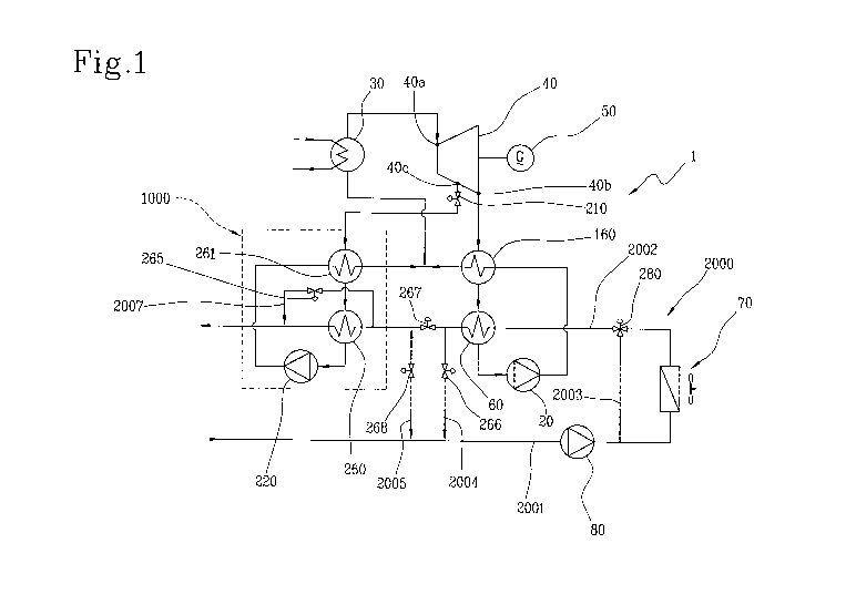
With reference to the figures, 1 denotes in its entirety a plant for energy
production
by an Organic Rankine Cycle (ORC) according to the present invention.
The plant 1 comprises a closed circuit in which an organic working fluid
circulates,
having a high or medium molecular weight. The fluid can be selected from a
group
comprising hydrocarbons, ketones, fluorocarbons and siloxanes.
CA 02872687 2014-11-04
WO 2013/171685 PCT/1B2013/053960
- 9 -
The plant 1 comprises a heat exchanger/evaporator 30 which exchanges heat
between a high-temperature source and a working fluid, such as to heat,
evaporate and superheat the working fluid; a turbo-expander 40 supplied by the
working fluid in the vapourised state in outlet from the heat exchanger 30,
such as
to realize a conversion of the heat energy present in the fluid into
mechanical
energy using a Rankine cycle; a generator 50 operatively connected to the
turbo-
expander 40, in which the mechanical energy produced by the turbo-expander 40
is converted into electrical energy; a condenser 60 where the working fluid in
outlet
from the turbo-expander 40 is condensed and sent to at least a pump 20. The
fluid
is sent from the pump 20 to the heat exchanger 30.
The illustrated plant 1 further comprises a recuperator 160 interposed between
the
turbo-expander 30 and the condenser 60. In the recuperator 160 the organic
fluid
vapour discharged from the turbine 40 is used to heat the liquid in delivery
from
the pump 20. In this way the quantity of heat exchanged by the evaporator 30
can
be reduced and thus the overall performance of the cycle is increased.
According to the embodiment represented in figure 1, the plant 1 further
comprises
a cogenerating and recovering circuit 1000 connected to an auxiliary opening
40c
(in this case for extraction) of the turbine 40 by means of a first valve 210.
The cogenerating and recovering circuit 1000 comprises a first exchanger 21, a
second exchanger 260 and a pump 220.
The organic working fluid, extracted from the turbine 40 at an intermediate
__ pressure of between entry and discharge pressures, is sent-to-the-first-
exchanger--
261, with the aim of pre-heating the organic fluid in the liquid phase which
is re-
injected into the plant. In outlet from the first exchanger 261, the organic
fluid is
sent to the second exchanger 260, where it yields heat to a heat-carrying
fluid
which transports the heat generated by the ORC plant. The transformations
which
occur in the exchangers 260 and 261 are represented in the diagrams T-s of
figure
1A and T-q of figure 1B. As can be observed in the diagrams, the organic fluid
is
extracted from the turbo-expander at temperature Tsp. Given the thermodynamic
nature of the organic fluid and the operating parameters of the plant, at
temperature Tsp the organic fluid is strongly superheated. For example
extracted
CA 02872687 2014-11-04
WO 2013/171685 PCT/1B2013/053960
- 10 -
fluid is at a temperature of about 250 C, while the heat-carrying fluid must
be
heated from 60 C to 80 C. The organic fluid extracted from the turbo-expander
is
cooled in the exchanger 262 to temperature Tin. The fluid at temperature Tin
then
enters the second exchanger 260 where it yields heat to the heat-carrying
fluid
and is brought to temperature Tout. By cooling the organic fluid reaches the
saturated liquid condition or, if required, the under-cooled liquid condition.
From
this condition the liquid is pressurized by the pump 220 and pre-heated in the
first
exchanger 261. When the pre-heating is terminated, the organic liquid is
injected
into the main thermal cycle, in inlet to the evaporator 30.
Figure 1 also partially illustrates a heat-carrying circuit 2000 for the heat-
carrying
fluid which transports the heat generated by the plant 1. The heat-carrying
circuit
2000 comprises an outward branch 2001 towards a sink 70 and a return branch
2002 which passes across the condenser 60 and the second exchanger 260 of the
plant 1. A pump 80 is arranged on the outward branch. A first bypass branch
2003
with a second three-way valve serves to exclude (or not) the sink 70. The
return
branch section 2002 interposed between the condenser 60 and the second
exchanger 260 of the plant 1 is connected to the outward branch via two
connecting tracts 2004, 2005 provided with respective third and fourth valves
266,
268. A further fifth valve 267 is arranged on the return branch between the
two
sections 2005, 2006 provided with the third and fourth valve 266, 268. A
second
bypass branch 2007 provided with a sixth valve 265 is located on the return
_branch 2002_and serves to-prevent-the- heat-carrying-fluid-from transiting-
through
the second exchanger 260.
The illustrated plant enables a good working flexibility. In the following the
main
functioning set-ups are described.
A ¨ purely electrical set-up: the first valve 210 is closed, the first and the
second
exchangers 261 and 260 are not supplied, the third valve 266 is open and the
pump 80 guarantees the flow supply to the condenser 60 with relatively cold
water,
by way of example between 30 and 50 C in inlet, thanks to the dissipation of
heat
via the sink 70, or alternatively cooling turrets or another solution. In
these
CA 02872687 2014-11-04
WO 2013/171685 PCT/1B2013/053960
- 11 -
conditions the electrical performance is maximized thanks to the minimizing of
the
fluid pressure in the condenser.
B ¨ total cogenerative set-up: there are two different possible set-ups, B1
and B2.
B1 ¨ in a case in which the thermal use requires a heat flow with a very
limited
heat rise DT, for example in the region of 5-10 C, the recycling extraction is
kept
out of service (first valve 210 closed) and in this case, with the third and
fourth
valve 266, 268 closed, and the sixth valve 265 open, all the heat discharged
from
the turbo-expander 40 is recycled into the condenser 60 with typical
temperature
levels of inlet/outlet of 60/70 C or 70/80 C or the like.
B2 ¨ in a case where the thermal use requires higher temperature gradients DT,
for example 20-30 C or even more, the condenser 60 and the second exchanger
260 are operated in series; the sixth valve 265 is now closed, the first valve
210 is
open and the third and fourth valve 266 and 268 are closed, or the fourth
valve
268 can also partialise the flow in order better to restart the load between
the
condenser 60 and the second exchanger 260; in this case the heating of the
heated fluid vector occurs in part with vapour at greater pressure (in the
exchanger
260) and in part at a lower pressure (in the condenser), enabling a
cogeneration
with a greater electrical yield; the sharing of the thermal load in the
condenser 60
and in the second exchanger 260 depends on the pressures at discharge and on
extraction of the turbo-expander 40 and on the requested temperature level.
Typical inlet temperature levels can be 60-90 C, 70-100, 80-110 C. The process
is
described by the diagrams in figure 1C.
C ¨ partial cogenerative set-up; this set-up is actuated simply by closing the
fifth
valve 267 and opening the third valve 266 and the fourth valve 268 and also,
obviously, the first valve 210. In this case the condenser 60 and the second
exchanger 260 are uncoupled and the condenser 60 can be flushed with
relatively
cold fluid at 30-50 C so as to maximize the electrical effectiveness of the
cycle,
while only a fraction of the vapour is drawn from the extractor, which expands
in
the turbo-expander 40, enabling an optimized functioning in the periods of low
thermal load, but not zero. The set-up is described in figure 1D.
CA 02872687 2014-11-04
WO 2013/171685 PCT/1B2013/053960
- 12 -
In a different embodiment represented in figure 2 (in which the heat-carrying
circuit/s are not illustrated), instead of the cogeneration and recycling
circuit 1000,
the plant 1 comprises an inlet circuit 3000 of working fluid into the turbo-
expander
40 aimed at performing a cycle at two pressure levels. This inlet circuit 3000
comprises a connecting branch provided with a vaporizer 300 which connects a
point located downstream of the pump 20 and the recycler 160 and upstream of
the heat exchanger 30 with the opening of the auxiliary 40c (in this case
inlet) into
the turbo-expander 40.
In both illustrated embodiments the turbo-expander 40 is of the type described
and
illustrated in following figure 3.
The expansion turbo-expander 40 is advantageously of the multi-stage
centrifugal
radial type (oufflow). In other words, working fluid flow enters the turbo-
expander
40 along an axial direction in a radially more internal zone of the turbo-
expander
40 and exits, expanded, along a radial or axial direction in a radially more
external
zone of the turbo-expander 40. In the pathway between the inlet and the outlet
the
flow continues to distance, while expanding, from the rotation axis X-X of the
turbo-expander 40.
The turbo-expander 40 comprises a fixed casing 101 formed by a circular front
half-casing 102 and by a rear half-casing 103. A sleeve 104 is cantilevered
from
the rear half-casing 103, constrained to a bearing structure of the plant.
In the internal volume delimited by the front 102 and rear 103 half-casings, a
rotor
105 is housed which- is solidly constrained to a -shaft--106¨in-- turn--
rotatably ¨
supported in the sleeve 104 by bearings (not illustrated) so as to be free to
rotate
about a rotation axis X-X.
At the position of the rotation axis X-X, the front half-casing 102 affords an
axial
inlet opening 40a, and at a radial peripheral portion of the casing 101 a
discharge
opening 40b is afforded, radially peripheral at a diffuser 107.
The rotor 105 comprises a single rotor disc 108 constrained to the shaft 106,
perpendicular to the rotation axis X-X and exhibiting a front surface 109
facing
towards the front half-casing 102 and a rear surface 19 facing towards the
rear
CA 02872687 2014-11-04
WO 2013/171685 PCT/1B2013/053960
- 13 -
half-casing 110. A passage volume for the organic working fluid is delimited
between the front surface 109 of the rotor disc 108 and the front half-casing
102.
The front surface 109 of the rotor disc 17 bears three series of rotor blades
111a,
111b, 111c. Each series comprises a plurality of flat rotor blades arranged
about
the rotation axis X-X. The rotor blades of the second series 111b are arranged
in a
radially external position with respect to the rotor blades of the first
series 111a
and the rotor blades of the third series 111c are arranged in a radially
external
position with respect to the rotor blades of the second series 111b.
Three stator blades 113a, 113b, 113c are mounted on an internal surface 112
facing towards the rotor 105 of the front half-casing 102. Each series
comprises a
plurality of flat stator blades arranged about the rotation axis X-X. The
stator
blades of the first series 113a are arranged in a radially internal position
with
respect to the rotor blades of the first series 113a. The stator blades of the
second
series 113b are arranged in a radially external position with respect to the
rotor
blades of the first series 111a and in a radially internal position with
respect to the
rotor blades of the second series 111b. The stator blades of the third series
113c
are arranged in a radially external position with respect to the rotor blades
of the
second series 111b and in a radially internal position with respect to the
rotor
blades of the third series 111c. The turbo-expander 40 thus exhibits three
stages.
Internally of the turbo-expander 40, the working fluid flow that enters the
axial inlet
opening 40a is deviated by a deflector 114 which exhibits a convex circular
shape,
is mounted fixed on the casing 103 in front of the rotor 105 and is arranged
coaxially of the rotation axis X-X with the convexity facing towards the flow
in inlet.
The deflector 114 extends radially starting from the rotation axis X-X up to
the first
series of stator blades 113a. The stator blades of the first series 113a are
integrated in the peripheral portion of the deflector 25 and exhibit an end
mounted
on the internal surface 112 of the front half-casing 102. In greater detail,
the
deflector 114 is defined by a slim convex plate with radial symmetry which
exhibits
a convex/concave central portion 114a with the convexity facing towards the
front
half-casing 102 and towards the axial inlet opening 40a and an annular
radially
more external portion 114b that is concave/convex with the concavity facing
CA 02872687 2014-11-04
WO 2013/171685 PCT/1B2013/053960
- 14 -
towards the front half-casing 102. The front half-casing 102 and the radially
more
external portion 114b of the deflector 114 delimit a conduit which guides the
working fluid towards the first stage (rotor blades of the first series 111a
and stator
blades of the first series 113a) of the turbo-expander 40.
The front surface 109 of the rotor disc 108 and the surface 112 of the front
half-
casing 102 bearing the stator blades 113a, 113b, 113c diverge one from the
other
in a gradually distancing direction from the rotation axis (X-X) starting from
the first
stage. The radially more external blades exhibit a height of blade that is
greater
than the radially more internal blades.
The turbine 4 further comprises the diffusor 107 for the recycling of the
kinetic
energy located in a radially external position with respect to the third stage
(formed
by the rotor blades of the third series 11 c and stator blades of the third
series
113c) and defined by the front surface 109 of the rotor disc 108 and the
opposite
surface 112 of the front half-casing 102. A volute 115 communicating with an
outlet flange is located on the radially external perimeter of the casing 101,
at the
outlet of the diffuser 107.
The radial distance Rd between the second and third stage, i.e. between the
rotor
blades of the second series 111b and the stator blades of the third series
113c is
greater than the radial distance between the first and the second stage or,
more in
general, the radial distance between the other stator and rotor blades
adjacent
thereto.
By way of example, the radial distance of the adjacent blades is about 5mm
while
the radial distance Rd between the second and the third stage is about 50mm,
i.e.
10 times greater.
An annular chamber 116 for injection/extraction of the organic working fluid
is
delimited between the second and the third stage.
A conduit 117 (or a plurality of conduits) is afforded in the front half-
casing 102,
which opens into the chamber 116 and defines the auxiliary opening 40c of the
turbo-expander 40. The conduit 117 further opens on a front wall 102a of the
front
half-casing 102. Appropriate pipes and/or connectors mounted on the front wall
CA 02872687 2014-11-04
WO 2013/171685 PCT/1B2013/053960
- 15 -
102a enable injecting or removing the organic working fluid into or from the
turbo-
expander 40.
In the embodiment of figure 1, the conduit 117 is connected to the
cogenerating
and recycling circuit 1000. In the embodiment of figure 2, the conduit 117 is
connected to the injection circuit 3000 of working fluid into the turbo-
expander 40
that is destined to perform a cycle at two pressure levels.