Note : Les descriptions sont présentées dans la langue officielle dans laquelle elles ont été soumises.
CA 02877966 2014-12-29
- 1 -
DISC-SHAPED TOY
Field of the invention
The invention relates to a toy.
Prior art
Dice are known as toys, and also other toys are known in a
very wide variety of shapes, for example rectangular or
spherical, which toys, on reaching their rest state after
being thrown, display or show the currently thrown numbers,
colors, symbols or images, etc.
Summary of the invention
It is the object to provide a further toy, in particular a
toy which provides additional playing possibilities.
This object is achieved with the features of Claim 1.
Owing to the fact that the toy comprises a housing with at
least one viewing opening and a rotary body which is arranged
in the housing, is mounted rotatably therein, is formed with
an unbalanced mass and is visible through the viewing opening
and is provided in the viewing area with at least two
different markings, new playing possibilities arise. The
unbalanced mass of the rotary body sets the latter rapidly
and persistently into rotation from a current starting
position relative to the housing when the toy is moved, for
example after punting the toy with a miniaturized ice hockey
stick. Upon stopping at the end of the rotation, the rotary
I
CA 02877966 2014-12-29
- 2 -
body is again in the rest state and in a certain position
relative to the housing, wherein this second position may,
but does not have to, differ from the first position. The
second rest state may by chance correspond exactly to the
first rest state, comparable to a dice which, after being
thrown again, by chance displays the same number of pips as
during the first throw. The unbalanced mass is formed, for
example, by a weight arranged on one side of the rotary body
or, in another variant, can also be formed by an eccentric
axis of rotation of the rotary body.
Since the housing is of substantially cylindrical design with
an upper side and a lower side, and has a diameter of upper
and lower side greater than the height of the housing, and in
particular when the housing is configured in a disk-shaped
manner with the proportions of an ice hockey puck, extended
playing possibilities are also provided. In particular, it is
possible to use this disk-shaped toy as a miniaturized puck
in a miniaturized ice hockey game, for example a table ice
hockey game.
In an advantageous manner, a viewing opening is provided in
each case on the upper side and on the lower side of the
housing, in particular opposite each other, and/or at least
one viewing opening is formed on the cylindrical outer wall
of the housing. In addition, it is particularly advantageous
to provide the upper and/or the lower side of the rotary body
with at least two or, depending on the embodiment, a
multiplicity of signs, symbols and/or colors which are
visible from the outside through the viewing window(s) in the
housing. By this means, the rotary body, depending on its
defined position, displays one or more of said signs, symbols
CA 02877966 2014-12-29
- 3 -
or colors which, in turn, may, but do not have to, differ
from those of the original position. For example, with
reference to colors assigned by players, it is thereby
possible to determine one of a plurality of players who has
the right, as the next player, to strike against the toy and
to displace the toy. This can take place, for example, until
one of the players involved manages to strike/push the toy
over a goal line, for example in a miniaturized goal, and the
game is continued with a changed score or is ended, in a
manner analogous to a genuine ice hockey game.
In a further particularly advantageous variant embodiment,
the housing is designed in two parts and preferably so as to
be closable and openable by means of closure elements. By
this means, the toy is openable, for example for cleaning,
maintenance or repair purposes, and is then closable again,
as a result of which the interior of the toy or of the
housing is protected from soiling. It is also thereby
possible to change one rotary body for another rotary body
with different markings in order to provide different playing
possibilities. The closure elements are advantageously
designed as a clamping closure with resilient clamping means.
In yet other embodiments, the toy is configured as a single
part, or upper and lower side of the housing, once joined
together, are connected to each other, for example by means
of pressing, welding or adhesive bonding, such that the toy
is no longer openable.
In a preferred variant, the rotary body and the housing have
at least one interacting stop element. In a particularly
advantageous manner, the stop element is designed in such a
CA 02877966 2014-12-29
- 4 -
manner that it has a magnet and a ferromagnetic couterpart
and/or a magnetic couterpart. In an advantageous manner, a
plurality of stop elements are provided in such a manner that
a magnet arranged on the rotary body and a plurality of
couterparts on the housing form a plurality of stop elements.
In this case, ferromagnetic and magnetic couterparts are
preferably arranged alternating circularly on an inside of
the housing. The magnet is preferably arranged in the rotary
body in a magnet shaft recessed therein.
By configuration of the toy with at least one stop element,
the rotary body can be set into rotation from an exactly
defined starting position relative to the housing, for
example by a strike with the already mentioned miniaturized
hockey stick against the toy, in such a manner that the
latter, after reaching its rest state, stops again in an
exactly defined position relative to the housing. Said
exactly defined position may, but does not have to, differ
from the starting position. It is therefore possible to
display signs, symbols and/or colors exactly through the
viewing window(s) in such a manner that they can be displayed
to the outside clearly, i.e. without being overlapped by an
edge of the viewing window(s). This helps to avoid unclear
situations which could arise if the signs, symbols or colors
mentioned are at least partially overlapped by the edge of
the viewing window or of the viewing windows and are only
partially displayed.
Alternatively or in addition, in other variant embodiments,
the stop element or the stop elements is or are formed by
parts with mechanical interlocking connection on the rotary
body and on the housing, preferably in the form of support
CA 02877966 2014-12-29
- 5 -
rings on the rotary body and support rings on the housing,
which support rings are formed with mutual wavy parts.
Advantages are afforded here in particular by the fact that,
after reaching the rest state, the toy or the exactly defined
end position of the rotary body, and therefore the relative
position of the signs, symbols or colors with respect to the
housing, cannot be influenced by a magnetic environment and
therefore a result may be falsified.
In a further embodiment, a guide axis of the rotary body is
guided in a guide depression of the housing, in particular so
as not to be tiltable laterally. In one variant embodiment, a
rotary body point is mounted in the guide depression, which
produces minimal friction. Alternatively or in addition, the
rotary body point is mounted with a rolling bearing or a
plurality of rolling bearings, for example ball bearings.
This affords important advantages insofar as the rotary body
is securely mounted in such a manner that it cannot tip up
irrespective of the ferocity of a strike or impact on the toy
and, in addition, irrespective of the relative position of
the toy or of the rotary body, and is nevertheless rotatable
in an easy-running manner.
In another embodiment, the cylindrical outer wall of the toy
is advantageously also of outwardly curved design, as a
result of which it can be ensured that the toy falls onto the
flat outer surfaces of the housing upper side or lower side
should the toy by chance come to lie on the cylindrical outer
wall thereof before the rest position is reached. This
behavior of the toy is also supported in that, in a further
advantageous embodiment, the toy is formed with a sliding
edge which protrudes on the upper side and/or lower side from
CA 02877966 2014-12-29
- 6 -
the housing. The sliding edge is advantageously formed
outward and is of rounded design in such manner that said
sliding edge makes even a random, but rather improbable, rest
position in an oblique intermediate position on the cylinder
edge of the toy impossible. In addition, the sliding edge
prevents signs, symbols or colors which are imprinted or
placed onto the housing upper side and/or lower side from
being able to be scratched or damaged or become worn with
increasing use of the game. In other embodiments, housing
depressions or recesses, in which signs, symbols or colors
can be provided or inserted in a protected manner, are also
provided.
Brief description of the drawings
Further preferred embodiments and advantages of the invention
emerge from the dependant claims and from the description
below with reference to the figures, in which:
figure 1 shows a perspective illustration of a toy,
figure 2 shows a sectional view of the toy,
figure 3 shows a perspective view of a rotary body,
figure 4a shows a perspective view of an inside of a
cylindrical housing upper part,
figure 4b shows a perspective view of an inside of a
cylindrical housing lower part,
figure 5a shows an exploded illustration of a toy with
I
. .
' CA 02877966 2014-12-29
- 7 -
counterparts arranged along a housing circumference opposite
a magnet,
figure 5b shows a view from above of the cylindrical housing
upper part of the toy according to figure 5a,
figure 5c shows a sectional view through the toy according to
figure 5a along an axis A-A according to figure 5b,
figure 6a shows an exploded illustration of a toy with
counterparts arranged opposite the magnet on a lower flat
surface of the inside of the housing,
figure 6b shows a view from above of the cylindrical housing
upper part of the toy according to figure 6a, and
figure 6c shows a sectional view through the toy according to
figures 6a along an axis C-C according to figure 6b.
Ways of implementing the invention
Figure 1 shows a diagrammatic illustration of a toy 1 which
has a housing which is joined together from a housing lower
part 2 and a housing upper part 3 and is designed to be
closable and openable in a clamped manner with a closure
element 4. In addition, the housing is formed with an
outwardly curved cylindrical outer wall 5, and also with
sliding edges 6, 6' on both sides of the toy 1. Furthermore,
in the embodiment shown, the sliding edges 6, 6' are
outwardly formed with projections 7, 7', by means of which
signs, symbols or colors can be provided or inserted on the
cylindrical outer wall 5 in a protected manner, wherein care
=
CA 02877966 2014-12-29
- 8 -
should be taken to ensure that, as far as possible, they are
not placed in the region of the greatest curvature 5. In
addition, signs, symbols or colors can also be provided or
placed on an upper and/or lower flat surface 8, 8' (figure 2)
of the housing 2, 3. Furthermore, in the variant shown, a
viewing window or a viewing opening 9 is provided in the flat
surface 8. In addition, an identical viewing window or an
identical viewing opening 9' is also provided opposite in the
flat surface 8' (figure 4b).
Figure 2 shows a sectional view of the toy 1, with the
housing and the rotary body 10 which is insertable in the toy
1 so as to be mounted rotatably about an axis x-x, in the
manner of a gyroscope. An upper and a lower guide axis 11,
11' together with the respective rotary body points 12, 12'
are admitted here into corresponding guide depressions or
bores 13, 13' of the housing 2, 3 for the purpose of reducing
friction. In the exemplary embodiment shown, the rotary body
10 slides with support rings 14 of the rotary body 10 on the
support ring 15 (figure 4a, 4b) formed on the housing 2, 3.
With an unbalanced mass weight 16 (figure 3), the rotary body
10 can be set into rotation about the axis of rotation x-x
thereof by a movement of the toy 1. In order to orient the
rotary body 10 in an exactly defined manner in relation to
the housing 2, 3 as it stops, at least one stop element is
provided for the rotary body. The stop element is preferably
formed by a magnet 17 which can be arranged, for example, in
a recessed magnet shaft in the rotary body, and is formed by
at least one corresponding ferromagnetic counterpart 18, for
example in the form of a rod or a plate made of iron, on an
inside of the housing 2, 3 or in depressions of the upper or
lower side of the housing. A plurality of stop elements are
CA 02877966 2014-12-29
- 9 -
generally provided, and this is achieved by a plurality of
couterparts. Instead of or in addition to ferromagnetic
couterparts, magnetic couterparts can also be provided.
Figure 3 shows a diagrammatic view of a rotary body 10, as
already mentioned in figure 2. In this case, for example, a
sign circle, symbol circle or color circle 19, 19' which is
divided into sectors, is provided on the upper and lower side
of said rotary body, depending on the variant embodiment,
said circles being visible from outside the toy 1 through the
viewing windows 9, 9'.
The magnet 17 also illustrated by figure 3 is oriented and
adapted with respect to magnetic strength in such a manner
that, when the rotational movement of the rotary body 10
about the axis z-z eases off (figure 2), the magnet is
aligned with the ferromagnetic couterparts 18 embedded in the
housing 2, 3 and the rotary body 10, as mentioned, stops in
an exactly defined rest position. The magnet and each
couterpart form a stop element. The signs, symbols or colors
are therefore completely and entirely visible from the
outside through the viewing windows 9, 9'. In particular,
they are not partially covered or overlapped by a housing
part 2, 3 after reaching the rest position.
While the unbalanced mass weight 16 placed in the rotary body
10 serves to bring the rotary body 10 into rotation and to
keep the latter in rotation for as long as possible (for
which purpose the magnet 17 also serves in the embodiment
illustrated), the guide axes 11, 11', the rotary body points
12, 12' and the support ring 14 of the rotary body 10, and
also the support ring 15 of the housing 2, 3 are configured
CA 02877966 2014-12-29
- 10 -
in such a manner that the friction is as low as possible and,
as a result, a braking effect is effectively reduced.
Figure 4a shows a diagrammatic view of the inside of a
cylindrical housing upper part 3 and figure 4b shows a
diagrammatic view of an inside of a cylindrical housing lower
part 2. Particularly shown here are the ferromagnetic
couterparts 18 which are designed in such a manner that, as
mentioned, they orient the rotary body 10 in relation to the
housing 2, 3 by means of the magnet 17 such that, at the
moment of the rest position, an entire sign, a complete color
or an entire symbol is visible in the viewing window 9, 9'.
In addition, two oppositely arranged, resiliently acting
closure elements 4 are illustrated, said closure elements
latching into corresponding, slot-shaped openings 20 when
housing lower part 2 and housing upper part 3 are pushed
together. The latching connection can be released again by
hand, as a result of which the housing is openable again.
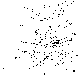
Figure 5a, for the purpose of better illustration, shows an
exploded illustration of a toy 1' which is formed with
ferromagnetic and magnetic couterparts 18, 18' opposite the
magnet 17 in order to form the stop elements, wherein the
couterparts 18, 18' are alternately arranged circularly at
regular intervals in the interior of the housing lower part
2. In the variant embodiment shown, magnet 17 and
ferromagnetic counterparts 18 act in an attracting manner to
one another, and magnet 17 and magnetic counterparts 18' are
arranged in such a manner that they act in a mutually
repelling manner.
The arrangement of magnet 17 with ferromagnetic and magnetic
CA 02877966 2014-12-29
- 11 -
counterparts 18, 18' according to figure 5a has the following
effect when playing with the toy 1': first of all, the rotary
body 10 comes into a persistent rotary movement in the
interior of an assembled toy 1' during a game, for example by
means of a strike with a miniaturized ice hockey stick (not
illustrated), wherein the toy 1' itself is, for example, hit
away on a miniaturized ice hockey field (likewise not
illustrated). After the toy 1' finally comes to rest, for
example at a point on the field mentioned, the rotary
movement of the rotary body 1' gradually decreases in
rotational speed, primarily because of friction.
If, shortly before the rotary body 10 comes to a standstill,
the magnet 17 then comes to lie relatively close to one of
the ferromagnetic counterparts 18 arranged on the housing
circumference, the attracting force of the magnet 17 acts on
said counterpart, and the rotary body finally comes to a
standstill in an aligned manner. That is to say, one of the
ferromagnetic couterparts 18 and the magnet 17 form a line
with the circle center 21. The signs, symbols and/or colors
(not shown for the sake of better clarity) which, in the
embodiment shown, are provided circularly at regular
intervals on an upper and a lower surface of a disk 22 then
come to lie aligned exactly through the viewing windows 9, 9'
in such a manner that they are clearly displayed to the
outside, i.e. without being overlapped by an edge of the
viewing window(s) 9, 9'. As mentioned, this helps to avoid
unclear situations which could arise should the signs,
symbols and/or colors mentioned be at least partially
overlapped by the edge of the viewing window or of the
viewing windows 9, 9' and therefore be only partially
displayed.
CA 02877966 2014-12-29
- 12 -
If, by contrast, shortly before the rotary body 10 comes to a
standstill, the magnet 17 comes to lie relatively far from
one of the ferromagnetic couterparts 18 arranged on the
housing circumference, i.e. approximately in the region of
the center between two ferromagnetic counterparts 18, and
therefore relatively close to the region of a magnetic
counterpart 18', the magnet 17 is repelled by the magnetic
counterpart 18' and therefore brought into the vicinity of
one of the ferromagnetic counterparts 18, and therefore the
previously described attraction between magnet and
counterpart is then in effect. Unclear situations with regard
to the illustration of the signs, symbols and/or colors
through the viewing windows 9, 9' are thereby prevented.
In other variant embodiments (not illustrated), the signs,
symbols and/or colors are placed in hollow regions 23 of the
rotary body 10 so as to be visible outside the toy 1' on both
sides through the viewing openings 9, 9', with no disk(s) 22
being provided. In yet another variant (not illustrated), a
second disk 22 (not illustrated) is arranged on the opposite
side of the rotary body 10. That is to say, the two disks 22
are arranged on a lower and an upper surface of the rotary
body 10 and form what is referred to as a sandwich therewith.
In this sandwich variant, only the outsides of the two disks
22 are printed with signs, symbols and/or colors which are
visible from outside the toy 1' through the viewing openings
9, 9'. In addition, the disk 22 is secured against relative
rotation and displacement in relation to the rotary body 10
by means of guides 22' and 22", with just one guide 22' or
22" also being formed in other embodiments.
CA 02877966 2014-12-29
- 13 -
Figure 5b shows a view from above of the cylindrical housing
upper part 3 of the toy 1' according to figure 5a, wherein,
by way of example, a "B" is illustrated in the viewing window
9, and therefore a player "B" should thus play next or move
the toy 1'.
Figure 5c shows a sectional view through the toy 1' according
to figure 5a, wherein said toy is illustrated cut open along
an axis A-A according to figure 5b. Said figure 5c
illustrates in particular a ball bearing 24 which makes it
possible for the rotary body 10 to be rotatable in a
particularly easy-running manner.
Figure 6a shows an exploded illustration of a toy 1" with
ferromagnetic and magnetic counterparts 18, 18' arranged
circularly around the circle center 21 in relation to the
magnet 17 on a lower flat surface of the inside of the
housing 2. As already described in the exemplary embodiment
of figure 5a, an attracting force acts between the
ferromagnetic counterparts 18 and the magnet 17 and a
repelling force acts between the magnetic counterparts 18'
and the magnet 17. That is to say, when playing with the toy
1", the rotary body 10 behaves in the same manner as
described in figure 5a.
In another variant embodiment (not illustrated), a
combination of the arrangement of the ferromagnetic and
magnetic counterparts, which arrangement is described in
figure 5a and figure 6a, can be implemented.
Figure 6b shows a view from above of the cylindrical housing
upper part 2 of the toy 1" according to figure 6a, wherein,
CA 02877966 2014-12-29
- 14 -
in analogy to the description of figure 5b, an "A" is
illustrated by way of example in the viewing window 9, and
therefore a player "A" should thus play next or move the toy
1,,.
Figure 6b finally shows a sectional view through the toy 1"
according to figure 6a along an axis C-C according to figure
6b. Rotary body points (12, 12') are in particular
illustrated therein, said rotary body points being mounted in
corresponding guide depressions (13, 13') and likewise
permitting particularly easy-running rotatability.