Note : Les descriptions sont présentées dans la langue officielle dans laquelle elles ont été soumises.
CA 02892925 2015-05-28
CONTAINER
[001]
BACKGROUND OF THE INVENTION
Field of the Invention
[0021 This invention relates to the field of packaging, and more particularly,
packaging for granulated products, such as for example, a powder.
Description of Related Art
[003] Currently, products in granular or powdered form, such as, for purposes
of
example without limitation, infant formula, flour, coffee, sugar, are packaged
in
containers. Scoops are provided within the package for measured dispensing of
such contents. Consumers or users of such containers have found that the
current packaging is d1fficult to handle with a single hand, and have found
that it is
difficult to open the container and to locate and remove the scoop from the
packaging upon the first use without experiencing spillage. Once the lid of
the
container is removed and/or opened, the contents are often loosely caked or
packed into parts of the interior of the lid or top of the container, which
leads to
spillage as the contents fall away from the lid or top. While some of the
falling
powder may fall back into the interior of the container, much of it is wasted
and
contaminated as it spills onto the surrounding workspace. Additionally, prior
containers do not offer adequate sealing of the contents after the container
has
been opened for the first time. This leads to the undesirable and inadvertent
leaking or escape of the contents from various poorly sealed areas of the
container.
1004] When the user wishes to withdraw a portion of the product from the
container, she must first dig around in the interior of the container with her
fingers
1
CA 02892925 2015-05-28
to find the scoop. This search and locate process contaminates the contents
and
soils the hands of the user, which can lead to more unwanted spillage as the
powder-coated fingers and hands are removed from the interior of the
container.
Once located, the scoop is withdrawn so that it can be used, and the scoop is
also
coated with the contents. The bowl of the scoop is also caked or packed with
the
contents. As the coating of powder and the packed bowl of powder loosen during
the removal process, more contents are contaminated and wasted as the coating
falls away from the hands, fingers, and scoop, and as any powder caked in the
bowl loosens and falls.
10051 Additional problems have been experienced with scoops that are
positioned in a more convenient location, perhaps against an interior or
exterior
wall. These additional problems include difficultly in grasping the scoop,
which
may be tightly fastened with adhesive against the wall and/or with a
mechanical
retainer or fastener that leaves very little clearance between the scoop and
surrounding structure of the container for grasping the scoop. These
undesirable
configurations typically will require more than one free hand for removal and
grasping of the scoop.
[006] Once the scoop is located and gripped by the user, it can be used to
withdraw and dispense the desired amount of product Typically, the scoop is
then
placed back into the container and the lid is replaced to close the container.
The
next time the product is to be withdrawn from the container, the process of
searching for the buried and powder-coated scoop is repeated. U. S. Patent No.
5,706,974 discusses the problem of storage of the scoop outside of the
granular
or powdered product.
10071 Users have also found that it is difficult to remove the last bit of
powder
from the nearly empty container because the shape of the container includes
tight
and closed spaces that are inaccessible to the scoop, and which has other
areas
having a shape that is different than the shape of the scoop. As a result, a
user
must resort to inverting the container to completely empty the contents, which
creates another instance of spillage and wasted contents.
[008] Manufacturers of such containers have also experienced a number of
challenges in fabricating the containers when using various types of
optionally
preferred thermo-forming and polymeric manufacturing processes and materials.
2
CA 02892925 2015-05-28
In many prior art attempts to manufacture such containers, various thermo-
molding processes are used. Those skilled in the relevant arts have long known
about the difficultly in producing various types of packaging containers using
thermo-formed polymeric materials.
[009] Such materials are subject to many variables that adversely and
unexpectedly result in product components being produced that can vary beyond
acceptable dimensional tolerance limits, which results in the need to scrap
defective containers and components of such container, and the need to produce
replacements. Also, polymeric materials can render mis-shaped component
profiles due to unexpected shrinkage and warping, and other thermo-forming
anomalies that leave entire production runs of containers and components for
containers destined for the scrap heap.
[0010] These types of manufacturing problems are especially pronounced in
containers formed from assemblies that incorporate more than one component,
such as where a top or lid and a collar assembly are fastened to a bottom part
of
the container. Problems in assembling such components can result if one or
both
of the components are out of tolerance or otherwise mis-shaped. Even where it
is
sometimes possible to assemble improperly dimensioned or mis-shaped
components, most polymeric container configurations have long been in need of
improved strength and rigidity characteristics to overcome such anomalies and
to
render such containers more durable for use in a wider array of environments.
100111 Still other users experience problems with prior art containers that
are
inadequate for use in circumstances where the ambient air pressure external to
the container changes drastically so as to create a significant pressure
differential
between the sealed interior space of the container and the extemal, ambient
atmosphere. This situation is most apparent in situations where a manufacturer
produces containers that are filled and sealed at a factory located at an
altitude at
or near sea level.
[0012] When such sea-level pressure containers are shipped to consumers
located at higher altitudes or elevations, the container packaging will have a
higher internal pressure, which creates a pressure differential that can be
significant. If the pressure differential is large enough, the container may
become
distended making it difficult to stack and store, and may even experience a
3
CA 02892925 2015-05-28
breach, leading to contaminated and wasted product. The opposite situation can
occur when containers that are filled and sealed at a higher altitude are
shipped to
lower altitude users. Upon opening, ambient air can rush into the interior
space of
the container and contaminate the contents.
[00131 When a container having a pressure differential is opened, the contents
may again spill due to the very rapid pressure equalization ejecting a cloud
of
powdered or other type of product contents. Attempts to overcome these
disadvantages have included thicker walled containers, which increases weight
and material costs, as well as round and cylindrical containers that may have
higher hoop stress strength, but which are less efficient and convenient to
stack
and store on a shelf.
100141 What has long been needed in the field of art is a container that
addresses the many issues surrounding prior art containers, and which most
importantly offers new and innovative ways to prevent and/or minimize
contamination, spillage, and waste of product contained in such containers. A
container has been sought that better enables access to the last bit of powder
in a
nearly empty container without the need to invert the container. It is also
advantageous to create a container that enables more convenient access to a
scoop for dispensing the powder. A container package that can be easily
manipulated by one hand while leaving the other hand free for opening and
dispensing is particularly needed for a variety of applications. A container
that is
easy to handle, grip, and to transport in quantity and to stack and store on a
shelf
has also been needed for a long time.
10015] Many attempts have still fallen far short of creating a more durable
container that incorporates improved rigidity and strength characteristics
that can
expand the range of acceptable dimensional tolerances and that can adapt to
and
more readily accommodate unexpected mis-shaped container component profiles.
The field of art continues to have a need for a container that can better
withstand
pressure differentials without compromise of the container, and which can
minimize the inconvenience of spillage and wasted product due to a rapidly
expelled cloud of product if the container is opened while subjected to a
pressure
differential.
4
CA 02892925 2015-05-28
SUMMARY OF THE INVENTION
[0016] Many of the problems of the prior art are addressed with the innovative
sealable containers of the invention, which enable previously unavailable
features
including improved sealing capabilities, new ways to control spillage of
powdered
contents, new integrated dispensing scoops, and strengthened containers that
can protect against spillage and damage to product due to adverse pressure
differentials between the sealed product container and the external
environment.
In one preferred configuration of the invention, a sealable container includes
walls
defining interior and exterior surfaces and an interior space. The walls can
preferably have an upper portion near an upper end of the walls that defines a
sealing flange that includes an internal edge, which defines an opening to the
interior space of the container. The sealable container also incorporates a
collar
having an interior surface which fits around the container near the upper
portion,
which together define a subcollar space between the exterior surface of the
container and the interior surface of the collar.
[0017] The preferred sealable container also includes a removable lid that is
pivotally or hingedly attached to the collar and which has an interior surface
that,
when the lid is in a closed position, covers and seals the opening of the
interior
space of the container. The lid preferably has a sealing wall that depends
from
the surface of the lid and projects toward the sealing flange of the collar,
and
which is dimensioned or sized to remain inward of the sealing flange when the
lid
is closed. In variations of any of the embodiments of the invention, the
sealing
wall of the lid can be used alone and in place of contemplated integral or
flexible
gaskets, and may also be used in combination therewith.
[0018] Even more preferably, the container includes in certain optionally
preferred embodiments either an integrally formed gasket carried from the
collar
and/or a separately formed flexible gasket, either of which are preferably
dimensioned to removably rest against the sealing flange. The gasket can be
carried from a surface of the container such as the interior surface of the
collar,
the interior surface of the walls, or the sealing wall of the lid, as well as
combinations thereof and wherein more than one gasket may be preferred for
use. When the lid is in the closed position, the gasket, the sealing wall and
the
sealing flange are arranged and dimensioned so that the sealing wall biases
the
5
CA 02892925 2015-05-28
flexible gasket against the intemal edge of the sealing flange to seal the
subcollar
space from the container interior, which prevents the contents of the
container
from spilling into the subcollar space.
[0019] In variations of these embodiments, the sealable container may also
incorporate a modified collar that includes a raised seat or similar feature
that
carries the gasket or to which the gasket is affixed. As with other versions
of the
invention, the raised seat is configured so that that gasket projects inwardly
to
bias against and to extend beyond the internal edge of the sealing flange,
which
also serves to control spillage of the contents of the container. More
preferably,
the gasket can be arranged to remain biased against the sealing flange when
the
lid is in an open position.
[0020] In additionally preferred and optional embodiments of the invention,
the
sealable container can also include a removable seal that is substantially
impervious to air, water, and even light if desired. The impervious seal
preferably
extends across the opening to seal the interior space and attaches to the
sealing
flange. In variations where the flexible gasket is included, the impervious
seal
preferably is situated underneath the gasket, and the flexible gasket flexes
to
enable removal of the removable seal and thereafter flexes back to rest
against
the sealing flange.
100211 In most embodiments of the inventive container, the lid is rotatably,
hingedly, and/or pivotally connected to the container with a live or
mechanical
hinge mounted between the lid and the collar so that the lid can move between
open and closed positions. In certain preferred configurations of the
invention, the
novel sealable container is arranged wherein its walls form the container to
have
an approximately cuboid shape. However, the present invention is susceptible
for
use in cylindrical, rectilinear, obloid, and many other types of container
packaging
and for use with all kinds of containerized substances including fluids as
well as
powdered and granular materials.
[0022] Some modifications of the embodiments of the invention also
contemplate inclusion of a removable scoop and a scoop holder that can be
attached to the interior surface of the lid for holding a scoop. The most
typical
scoops have a bowl that is carried from a handle. The scoop holder of the
invention is formed with a first bowl cover bracket and has a retainer that
6
CA 02892925 2015-05-28
immobilizes the handle. A first projection is also included that extends from
the
interior surface of the lid and which has a handle holding notch that holds
the
handle away from the interior surface in a grasping position so that it is
easy for a
user to grasp and remove the scoop from the scoop holder.
[0023] In still other variations of any of the embodiments of the inventive
sealable container, the sealing wall of the lid can be further modified to
funnel
inwardly toward a lower edge, either by a curved inwardly directed tapering of
a
lower edge of the sealing wall, or by a inwardly slanted or inclining tapering
thereof, or by a combination thereof.
[0024] The new and novel sealable container also contemplates further modified
lid arrangements that are compatible for use with any of the embodiments,
modifications, and variations of the invention. Such lid configurations are
directed
at improving control of powdered contents, and the improvements preferably or
optionally include the lid having a substantially domed central section that
is
dimensioned to be smaller than the sealing wall of the lid. More preferably,
the
substantially domed central section is joined to the lid by either the sealing
wall or
an angled wall, or both, wherein the angled wall tapers from the domed central
section down to the interior surface of the lid at a point that is proximate
to the
sealing wall. The novel capability and benefits of the substantially domed
central
section are evident upon righting a disoriented container in that the angled
wall
and the sealing wall cooperate to direct any powder contents that may have
accumulated within or become packed against the interior surface of the lid,
down
into the interior space of the container, which prevents entry into the
subcollar
space and other forms of spillage off of the lid upon opening the container.
Preferably, the angled tapered wall can have an angle relative to a vertical
direction of between about 10 and 75 degrees, and more preferably between
about 25 and 45 degrees, and even more preferably about 30 degrees.
100251 Many variations of possible domed lid configurations according to the
principles of the invention are contemplated and can include, for purposes of
example without limitation, the substantially domed central section extending
to
the sealing wall to define an area between approximately 20 percent and
approximately 80 percent smaller than the entire area defined by the removable
lid. Still other variations of the domed lid can be used with any of the
inventive
7
CA 02892925 2015-05-28
embodiments and include the substantially domed central section to project
upwardly with a height dimension that is between approximately 10 percent and
approximately 60 percent of a cumulative lid height dimension. In one
embodiment, the domed area is dimensioned to contain a volume sufficient for
storing a scoop, as described later.
[0026] As before and as described elsewhere herein, the innovative sealable
container embodiments can be furter modified to have the walls joining each
other and joining a bottom surface of the container to define junctions that
have a
unique and/or predetermined or a particular cross-sectional geometry. In these
variations of any of the embodiments of the invention, a modified scoop is
incorporated for removing contents from the interior space of the container.
The
modified scoop includes a bowl that has a rim which is substantially congruent
to
the particular cross-sectional geometry of the junctions between the walls and
between the walls and the bottom surface of the container.
[0027] This arrangement enables a user to conveniently remove all of the
contents of the container, whether powder or fluid, without the need to invert
the
container, which can result in unwanted spillage. These variations contemplate
the particular cross-sectional geometry of the junctions between the walls and
between the walls and the bottom surface to include any one of a number of
geometries including, for purposes of example without limitation, a right
angle,
multiple angles such as multiple obtuse angles, and curvilinear geometries
including a circular geometry having a particular radius. For each of these
respective geometries, the rim of the scoop bowl includes a portion that is
substantially congruent to the respective geometry, and/or which is flexible
and/or
deformable upon use to be made congruent thereto.
[0028] The sealable container of the present invention also can include many
different strength and rigidity improving features that can include the walls
of the
container having the upper portion defining on the exterior surfaces a
plurality of
interiorly projecting indentations or recesses that are spaced apart by
strengthening or stabilizing bridges. The indentations preferably include a
downwardly facing top surface or upper lug ledge. The collar is also modified
to
include a plurality of spaced apart flex clips or engagement lugs that are
formed
with retainer faces or upwardly facing surfaces. The flex clips preferably
depend
8
CA 02892925 2015-05-28
downwardly into the subcollar space and are positioned or juxtaposed to align
with
the plurality of indentations when the collar is fitted over the upper portion
of
receptacle of the container.
[0029] This arrangement enables the upwardly facing surfaces to engage the
downwardly facing top surfaces whereby the flex clips hold the collar to the
upper
end of the container. The flex clips may also preferably incorporate one or
more
stiffeners that increase the strength and rigidity of the flex clips to
optimize
engagement strength. The stiffeners also serve to improve an alignment
capability established by the flex clips, which effectively center and align
the collar
about the upper portion of the container as the collar is fitted onto the
upper
portion of the walls of the container.
[0030] Additionally preferred variations of the flex clip and indentation
modification include the upwardly facing surfaces being dimensioned to be
smaller than the downwardly facing surfaces of the indentations so that the
collar
and container can absorb dimensional tolerance errors and enable the collar to
fit
around the upper portion of the container even if they are not sized exactly
as may
be desired for a perfect fit. Further preferable modifications to the various
embodiments of the inventive sealable container include at least one of the
collar
and the upper portion of the walls to be formed from a substantially flexible
material.
[0031] Using a flexible material such a polymeric material like polypropylene
and/or polyethylene will enable at least one of the collar and the upper
portion of
the walls to flex to absorb dimensional tolerance errors and enable the collar
to fit
around the upper portion of the container. Either of these innovative
adaptations
are suitable for use with all of the variations of the embodiments of the
invention
and can, as a result, also accommodate shape errors and mismatch between at
least one of the collar and the upper portion of the walls to enable the
collar to fit
around the upper portion of the walls, even when unexpectedly or undesirably
misshaped collars and/or receptcles are encountered during manufacture and
assembly.
[0032] In yet another particularly preferred and optional modification to the
various embodiments of the invention described herein, the sealable container
employs a modified collar having a substantially J-shaped and/or U-shaped,
9
CA 02892925 2015-05-28
upside-down cross-section. In this variation, the J or U shaped cross section
includes an outward projecting long wall, a substantially rounded, stiffening
top
portion, and an inward short wall that cooperate to define the subcollar
space.
[0033] The invention is susceptible to still further optionally preferred
variations
wherein the container is strengthened by incorporating the plurality of
indentations
and the plurality of spaced apart fins or flex clips to be positioned in an
oppositely
paired relationship. In the application of a substantially cuboid container
shape,
the opposite pairing is established across opposite facing walls of the
container,
using generally 2-6 fins or clips per side. However paired, a force vector
coupling
is established between each of the pairs. This increases rigidity and
structural
stability and strength of the sealable container, and tends to absorb any
tolerance
mismatches when the collar is fitted onto the upper portion. Additionally,
this
particular arrangement of flex clips and indentations enables an aligning
capability
between the collar and the upper portion of the walls, which can be useful
during
assembly of the inventive sealable containers. The flex clips can be further
strengthen by including at least one stiffening rib on one of more of the flex
clips.
[0034] Still other contemplated modifications are suitable for use with all of
the
modifications, variations, adaptations already described, which include the
bottom
surface including pressure control features that can prevent deformation of
the
container, and which can also be adapted to enable controlled deformation to
relieve stress on the container due to internal pressure being higher than an
external ambient atmospheric pressure, which can occur when a sealed container
is subjected to pressure changes due to altitude changes and/or other types of
crushing forces that may be experienced during manufacture, filling with
product,
and during use and transit.
[0035] In this adaptation of the preferred embodiments of the invention, the
bottom surface includes a pressure control portion that is otherwise referred
to as
a central raised stiffener portion, which contrary to the plain meaning of the
word
stiffener, may also incorporate a flexible and/or collapsible pressure relief
section.
An outer planar portion that is substantially flat for resting on a surface
surrounds
the central raised stiffener portion. The central raised stiffener portion
preferably
projects or is directed towards the interior space in a plurality of steps
having riser
and tread portions, the riser portions generally project in a direction
substantially
CA 02892925 2015-05-28
upward relative to the outer planar portion and the tread portions are
approximately parallel to the outer planar portion. The plurality of these
riser and
tread steps further contemplate multiple variations.
[0036] In one version, the steps are stiffened by thickening in a cross-
section to
resist deformation due to pressure changes relative to the pressure inside the
sealed container. In another complementary version that can be used alone or
in
combination with the stiffened variation, an accordion or bellowed type
arrangement of the steps or series of steps are included, which flex or deform
in
response to pressure changes external to the sealable container so as to
lessen
the net pressure differential between the interior of the sealable container
and the
ambient outside pressure.
[0037] In still other variations of the embodiments of the invention, a
sealable
container includes a top wall, a bottom wall, a front wall, a rear wall, a
first side
wall, and a second side wall. Each of the walls has a substantially
rectangular
shape. The rectangular shape of each wall enables the container to be stored
easily on a shelf or counter-top. The top wall and portions of the front wall,
the
rear wall, the first side wall, and the second side wall form a lid. The lid
is pivotally
attached to the rear wall by a hinge. The lid can be opened by rotation
thereof
about the hinge. The front wall has at least one recess and the rear wall has
at
least one recess. The at least one recess of the front wall and the at least
one
recess of the rear wall are adjacent to the first side wall. The recesses
provide a
grip feature, which enables the user to manipulate the lid of the container
with one
hand when the container rests on a flat surface, e.g., a tabletop or a counter
top.
The container is preferably made of a polymeric material.
[0038] The container provided herein is suitable for holding granular material
or
powdered material, the container having a scoop furnished therewith. The scoop
has a handle and a bowl. The interior of the container is characterized by
having
corners that are congruent with the bowl of the scoop furnished with the
container.
The congruency of the bowl of the scoop with the corners of the container
enables
the user to remove the last bit of powder remaining in the container. A
flexible
seal can be applied to the interior of the container to provide a
substantially
moisture-impervious, oxygen-impervious seal for the granular material or
powdered material.
11
CA 02892925 2015-05-28
[0039] The lid is furnished with a scoop holder, whereby the scoop can be
stored outside the bulk of the contents of the container to enable easy, clean
access to the contents of the container. The container can be opened and
closed
with a single hand.
[0040] These variations, modifications, and alterations of the various
preferred and optional embodiments may be used either alone or in combination
with one another and with the features and elements already known in the prior
art
and also herein described, which can be better understood by those with
relevant
skills in the art with reference to the following detailed description of the
preferred
embodiments and the accompanying figures and drawings.
BRIEF DESCRIPTION OF THE DRAWING(S)
10041] Without limiting the scope of the present invention as claimed below
and
referring now to the drawings and figures, wherein like reference numerals,
and
like numerals with primes, across the drawings, figures, and views refer to
identical, corresponding, or equivalent elements, methods, components,
features,
and systems:
[0042] FIG. 1 is a perspective view of one embodiment of the container
described herein. In this figure, the lid of the container is closed. This
figure
shows a side of the container having a grip feature.
[0043] FIG. 2 is a perspective view of the embodiment of the container shown
in
FIG. 1 that depicts sides of the container not shown in FIG. 1 and a side of
the
container having a grip feature.
100441 FIG. 3 is a perspective view, greatly enlarged, of the area designated
by
the line 3-3 in FIG. 2. This figure shows a cut-away view of a mechanical
hinge.
[00451 FIG. 4 is an exploded perspective view of an assembly comprising a
collar and a lid. The assembly of the collar and the lid can be applied to a
tub-
shaped receptacle to form the container described herein.
[0046] FIG. 5 is a perspective view of a tub-shaped receptacle to which the
assembly comprising the collar and the lid, shown in FIG. 4, can be applied to
form the container described herein.
[0047] FIG. 6 is a side view in elevation of the embodiment of the container
shown in FIG. 1. This figure shows the front wall of the container, which has
a grip
feature.
12
CA 02892925 2015-05-28
[0048] FIG. 7 is an end view in elevation of the embodiment of the container
shown in FIG. 1. This figure shows the first side wall of the container, which
is
adjacent to the grip features of the front wall and the rear wall of the
container.
[0049] FIG. 8 is an end view in elevation of the embodiment of the container
shown in FIG. 1. This figure shows the second side wall of the container,
which is
not adjacent to the grip features of the front wall and the rear wall of the
container.
100501 FIG. 9 is a top plan view of the interior of the embodiment of the
container
shown in FIG. 1. In this figure, the lid is removed from the container.
[0051] FIG. 10 is a cross-sectional view taken along line 10 - 10 in FIG. 1.
This
figure illustrates the lid attached to the collar by means of a living hinge
to form an
assembly thereof.
[0052] FIG. 11 is a cross-sectional view taken along line 11 - 11 in FIG. 1.
This
figure illustrates a latch that can be used to maintain the lid in a closed
position.
[0053] FIG. 12 is a cross-sectional view taken along line 12 - 12 in FIG. 4.
This
figure illustrates the lid attached to the collar of the assembly comprising
the collar
and the lid.
[0054] FIG. 13 is a perspective view of the lid attached to the collar. This
figure
shows the interior surface of the lid incorporating an attached scoop holder
and a
restraint and standoff bracket for the handle of the scoop. This figure
further
shows a substantially moisture-impervious, oxygen-impervious seal attached to
the rim or sealing flange of the tub-shaped receptacle.
[0055] FIG. 14 is cross-sectional view taken along line 14 - 14 in FIG. 13.
This
figure illustrates attachment of the substantially moisture-impervious, oxygen-
impervious seal to the rim of the tub-shaped receptacle.
[0056] FIG. 15 is an exploded perspective view of the interior surface of the
lid
showing the scoop removed from the scoop holder and the restraint for the
handle
of the scoop.
[0057] FIG. 16 is a perspective view of another embodiment of the container
described herein. In this figure, the container lid is closed and a side of
the
container includes grip features.
[0058] FIG. 17 is a perspective view of the embodiment of the container of
FIG.
16, and rotated to show rear and bottom sides of the container that are not
shown
in FIG. 1.
13
CA 02892925 2015-05-28
100591 FIG. 18 is a bottom plan view of the embodiment of the container of
FIGS. 16 and 17 showing features of the bottom wall of the container that
include
stepped pressure compensating riser and tread features.
[0060] FIG. 19 is an elevation view of a first side wall of the embodiment of
the
container of FIG. 16 showing the front and rear gripping features.
[0061] FIG. 20 is a partial perspective view of the embodiment of the
container
of FIG. 16 having the lid removed for purposes of illustrating the collar and
the
arrangement of the impervious seal affixed and covering the opening of the
container.
[0062] FIG. 21 is another partial perspective view of the embodiment of the
container of FIG. 23 also having the gasket and impervious seal removed to
illustrate the collar as it is retained on the tub shaped receptacle of the
container.
[0063] FIG. 22 is a partial perspective view of the embodiments of the
container
shown in FIGS. 20 and 21 having the collar and the impervious seal removed to
show the collar engagement features of the upper portion of the receptacle.
[0064] FIG. 23 is a cross-section view of the upper end and sealing flange of
the
tub-shaped receptacle of the embodiment of the container of FIGS. 20 ¨ 22,
which
is taken along section line 23 ¨ 23 of FIG. 22. The impervious seal has been
added for improved illustration purposes.
[0065] FIG. 24 is a perspective view of the collar of the embodiments of the
container of FIGS. 16 - 22.
[0066] FIG. 25 is a cross-section view of the collar of the embodiment of the
container shown in FIG. 24 and taken along section line 25 - 25.
[0067] FIG. 26 is a cross-section view of the collar of the embodiment of the
container shown in FIGS. 16 ¨ 22 and taken along section line 26 ¨ 26 of FIG
24,
but having certain additional lid structure shown for illustration purposes.
[0060] FIG. 27 is a cross-sectional view of an alternative variation of the
sealing
wall illustrated in FIG. 26.
[0069] FIG. 28 is a cross-sectional view of another alternative variation of
the
sealing wall illustrated in FIG. 26.
[0070] FIG. 29 is a top plan view of the embodiment of the container of FIGS.
16
- 19 showing the top wall including the lid and cover assembly.
14
CA 02892925 2015-05-28
[00711 FIG. 30 is a perspective view of the underside of the lid of the
embodiment of the container of FIGS. 16 - 19 and illustrating a scoop holder
retaining a scoop.
[00721 FIG. 31 is a perspective view of the underside of the lid of FIG. 30
having
the scoop removed for further illustration of the scoop holder.
100731 FIGS. 32 and 33 are perspective views of the scoop in different
orientations to show alternative variations of the congruent rim of the bowl
of the
scoop.
10074] FIG. 34 is a section view of the lid of the embodiment of the container
of
FIG. 29 and taken along section line 34 ¨ 34 to show a laterally extending
cross
section of the domed and angled wall lid variation.
[0075] FIG. 35 is a section view of the lid of the embodiment of the container
of
FIG. 29 and taken along section line 35 ¨ 35 with a view directed towards
retainer
elements of the scoop holder.
[00761 FIG. 36 is a section view of the lid of the embodiment of the container
of
FIG. 29 and taken along section line 36 ¨ 36 with a view directed towards the
scoop holder bowl brackets.
[00771 FIG. 37 is a section view of the embodiment of the container of FIG.
18,
and taken along section line 37 ¨ 37, which depicts the bottom pressure
control,
centralized stiffener, and/or stepped portion modification to the bottom of
the
receptacle.
10078] FIGS. 38a and 38b are detail views taken about detail view lines 38 in
FIG. 37 and illustrate alternative flexible and pressure responsive, decreased
thickness cross-sectional configurations of the centralized stiffener or
stepped
portion of the bottom of the receptacle.
100791 FIGS. 39a and 39b are detail views taken about detail view lines 39 in
FIG. 37 and illustrate another alternative flexible and pressure responsive,
bellows
and/or pleated cross-sectional configuration of the centralized stiffener or
stepped
portion of the bottom of the receptacle.
DETAILED DESCRIPTION OF CERTAIN EMBODIMENTS AND VARIATIONS
[0080] As used herein, the expression "top wall" means the side of the
container
exclusive of the bottom wall, the first side wall, the second side wall, the
front wall,
CA 02892925 2015-05-28
and the rear wall of the container. The term "lid" means a hinged cover for a
hollow receptacle and is intended to include either an independently formed
and
removable lid and other variations that can include the lid alone, the lid and
collar
assembly, and other variations wherein the lid and/or collar are formed from
the
top wall of the container plus the upper portion of the first side wall, the
upper
portion of the second side wall, the upper portion of the front wall, and the
upper
portion of the rear wall of the container. As used herein, the term 'bracket"
means a wall-anchored fixture adapted to support a load.
[0081] Referring now to FIGS. 1, 2, and 5 - 9, a container 10 includes a top
wall
12, a bottom wall 14 with an interior bottom surface 14a, a front wall 16, a
rear
wall 18, a first side wall 20, a second side wall 22. The front wall 16
comprises an
interior major surface 16a, an exterior major surface 16b, an upper portion
16d,
and a lower portion 16e. The rear wall 18 comprises an interior major surface
18a, an exterior major surface 18b, an upper portion 18d, and a lower portion
18e.
The first side wall 20 comprises an interior major surface 20a, an exterior
major
surface 20b, an upper portion 20d, and a lower portion 20e. The second side
wall
22 comprises an interior major surface 22a, an exterior major surface 22b, an
upper portion 22d, and a lower portion 22e.
[0082] Although the container 10 and the later described variations and
modifications thereto are illustrated in the various descriptions and figures
to be
substantially cuboid, a cuboid shape is depicted only because such a shape is
sometimes found by those skilled in the relevant arts to be the more
challenging
type of container to describe, manufacture, and to use. However, the present
invention is susceptible for use with all shapes and sizes of containers
including
cylindrical, obloid, rectilinear, and other shapes, and for use with
containers
adapted for fluids as well as for the powdered materials and/or product
described
most often herein. Furthermore, each of the optional and preferred embodiments
of the invention contemplate interchangeability with all of the various
features,
components, modifications, and variations illustrated throughout the written
description and pictorial illustrations.
[0083] As can be seen in FIGS. 1, 2, and 4, in an exemplary embodiment of the
invention, an assembly of a lid and a collar of the container 10, which are
discussed here and in the context of other variations elsewhere herein, is
formed
16
CA 02892925 2015-05-28
from and/or includes a part of the top wall 12 and the upper portion 16d of
the
front wall 16, the upper portion 18d of the rear wall 18, the upper portion
20d of
the first side wall 20, and the upper portion 22d of the second side wall 22.
The lid
and the collar variations contemplated here may be formed integrally with the
walls, may be formed as an integral lid and collar assembly and/or
combination,
and may also be provided as a separate lid and a separate collar that can be
joined with a hinge or another type of pivotally and/or removable device or
connection to one or more portions of the walls. As will be described in more
detail below, the lid and collar arrangements can be attached and assembled to
the inventive containers in a variety of ways including clips, friction-fit
configurations, and using other equally desirable and optional components and
methods.
[0084] The lid is also described in more detail below in connection with the
various embodiments of the invention and will hereinafter be referred to by
the
reference characters "L" and "D" (see FIGS. 1, 2, 4, and 29-31) to refer to
the
various embodiments and variations thereof. Focusing initially on the lid "L"
of the
version illustrated in FIGS. 1, 2, and 4, lid "L" has an interior surface,
which will
hereinafter be referred to by the reference character "Li". The lid also has
an
exterior surface, which will hereinafter be designated by the reference
character
"Le", A hinge 24 attaches the lid "L" to the rear wall 18.
100851 The front wall 16 has a recess 26a positioned to facilitate gripping of
the
container 10 by the left thumb of the user. The rear wall 18 also has a recess
26b
positioned to facilitate gripping of the container 10 by the fingers of the
left hand of
the user. The recess 26a can further have an additional recess 27a to indicate
the
precise location in the recess 26a for the placement of the thumb of the user.
The
recess 27a is smaller in area than the recess 26a. The recess 27a is
preferably
circular in shape, but other shapes are also acceptable. The recess 26b can
further have an additional recess 27b to indicate the precise location in the
recess
26b for the placement of the desired finger of the user. The recess 27b is
smaller
in area than the recess 26b. The recess 27b is preferably circular in shape,
but
other shapes are also acceptable. The recesses 26a and 26b are positioned
adjacent to the first side wall 20 of the container 10.
17
CA 02892925 2015-05-28
t00861 In an altemative embodiment (not shown), the recesses 26a, 27a, 26b,
and 27b can be positioned to facilitate gripping of the container 10 by the
right
thumb of the user and by the fingers of the right hand of the user. In this
alternative embodiment, the recesses would be positioned adjacent to the
second
side wall 22 of the container 10.
[0087] In still another alternative (not shown), the front wall 16 can have
two
recesses and the rear wall 18 can have two recesses, one recess on the front
wall
16 and one recess on the rear wall 18 positioned to facilitate gripping of the
container 10 by the left thumb and the fingers of the left hand of the user
and one
recess on the front wall 16 and one recess on the rear wall 18 positioned to
facilitate gripping of the container 10 by the right thumb and the fingers of
the right
hand of the user. In this embodiment, pairs of recesses would be positioned
adjacent to both the first side wall 20 and the second side wall 22.
[0088] The hinge 24 prevents the lid "L" from descending when the product is
being accessed by the user, which would cause a nearly empty container to tip
over. The hinge 24 can be a living hinge or a conventional mechanical hinge. A
living hinge is a thin flexible web of material that Joins two rigid bodies
together. In
this case, the living hinge connects two segments of an object, i.e., the Ild
"L" and
the rear wall 18 of the container 10, to keep the segments together and allow
the
object to be opened and close .
[0089] The material used to make a living hinge is preferably a very flexible
polymeric material, such as, for example, polypropylene and polyethylene.
Living
hinges can be flexed numerous times without failure.
[0090] Conventional mechanical hinges include, but are not limited to, hinge
assemblies comprising a first panel having two or more sockets mounted on an
edge thereof and a second panel having two or more pins mounted on an edge
thereof, the aforementioned pins mating with the aforementioned sockets to
join
the edge of the first panel to the edge of the second panel, the pins and the
18
CA 02892925 2015-05-28
sockets allowing rotation of the first panel about the second panel.
[0091] The hinge 24 is designed in such a manner that when the lid "L" of the
container 10 is opened to enable the user to obtain access to the contents of
the
container 10, the lid "L" will not fall forward to the closed position.
Further, the lid
"L" will not fall too far backward beyond the open position desired, which
would
cause a container 10, when nearly empty, to tip over onto the rear wall 18.
Another type of equally suitable mechanical hinge can be seen with reference
to
FIGS. 16 ¨ 21, 24, and 29 - 31, among other figures and description discussed
elsewhere herein.
[0092] The top wall 12, the bottom wall 14, the front wall 16, the rear wall
18, the
first side wall 20, and the second side wall 22 enclose a hollow interior
space "H"
16 (FIGS. 5, 9) into which a product can be inserted. While the hollow
interior space
"H" can hold any solid or liquid product, the particular product for which the
container 10 is designed is typically a flowable solid material, such as, for
example, a powdered product andfor a granular product. Representative
examples of such a powdered product or granular product include, but are not
limited to, infant formula, flour, coffee, and sugar.
[0093] Referring now to FIGS. 13, 14, 20, 23, and 26, a substantially moisture-
impervious, oxygen-impervious seal 28 is attached to the interior major
surfaces
16a, 18a, 20a, 22a of the front wall 16, the rear wall 18, the first side wall
20, and
the second side wall 22, respectively_ Optionally, the substantially moisture-
impervious, oxygen-impervious seal 28 can also be impervious to light. A pull-
tab
28a on the substantially moisture-impervious, oxygen-impervious seal 28 can be
used to facilitate removal of the seal 28 by the user.
[0094] The substantially moisture-impervious, oxygen-impervious seal 28 can
be formed from a sheet of material substantially impervious to oxygen,
moisture,
and light. A material suitable for use in preparing the substantially moisture-
impervious, oxygen-impervious seal 28 can be a sheet of foil, such as, for
example, aluminum foil, or a foil made of some other metallic material, or a
19
CA 02892925 2015-05-28
combination of a layer of materials that can include a metallic, a polymeric,
and
other material layers.
[0095] In one embodiment, the substantially moisture-impervious, oxygen-
impervious seal 28 be applied at a position near the edges of the upper
portion
16d of the front wall 16, the upper portion '18d of the rear wall 18, the
upper
portion 20d of the first side wall 20; and the upper portion 22d of the second
side
wall 22 on the interior major surfaces 16a, 18a, 20a, 22a, of the front wall
16, the
rear wall 18, the first side wall 20, and the second side wall 22,
respectively, of the
container 10. The substantially moisture-impervious, oxygen-impervious seal 28
can be removed by pulling the pull-tab 28a of the seal 28 and removing the
seal
28 from the positions of attachment to the interior major surfaces 16a, 18a,
20a,
22a, of the front wall 16, the rear wall 18, the first side wall 20, and the
second
side wall 22, respectively, of the container 10.
[0096] Referring now to FIGS. 13, 15, 30¨ 31, 35, and 36, attached to the
interior surface "Li" of the lid "L" (and an interior surface "Di" of later
described lid
"D") is a scoop holder 30. The scoop holder 30 comprises a first bracket 30a
and
a second bracket 30b. The scoop holder 30 is capable of retaining a scoop 32
in
such a position so as to be separated from the product The scoop 32 comprises
a handle 34 attached to a bowl 36 wherein the handle may incorporate a
stiffener
34b (FIG. 330, 32 - 33). Other variations of equally preferred and optionally
desirable scoops 30 are discussed below and can be seen with reference to
FIGS. 30, 32, and 33, and in other places elsewhere herein.
[0097] The scoop 32 is positioned in the first bracket 30a and the second
bracket 30b in such a manner that the user is induced to remove the scoop 32
by
the handle 34, rather than by the bowl 36. Furthermore, the first bracket 30a
and
the second bracket 30b are positioned so that the scoop 32 is held by the
first
bracket 30a and the second bracket 30b in such a manner as to prevent the
powdered product or granular product from entering the bowl 36 of the scoop
32.
[0098] As discussed elsewhere, this feature is of particular benefit to users
of
the containers of the invention in view of the fact that such containers are
subjected to unpredictable amounts of jostling, shaking, upside-down or
inverted
shipment by truck, car, and mail carrier, and Impacts during manufacture,
distribution, and daily use by consumers. Such a container is possibly subject
to a
CA 02892925 2015-05-28
higher level of abuse in environments involving children and child care, such
as
where a parent carries a powdered product in a container such as those
described
herein in an automobile and/or in a heavily-used diaper bag, both of which can
experience the ravaging abuse of curious children at play.
[00991 The first bracket 30a of the scoop holder 30 covers the opening in the
bowl 36 of the scoop 32, thereby preventing the product in the container from
entering the bowl 36 of the scoop 32, which could lead to scattering product
outside of the container upon removal of the scoop 32 from the scoop holder
30.
The bowl 36 of the scoop 32 does not interfere with substantially moisture-
impervious, oxygen-impervious seal 28 when the scoop 32 is positioned in the
scoop holder 30.
[00100] The scoop holder 30 is positioned in such a manner that the handle
34
of the scoop 32 is prevented from contacting the substantially moisture-
impervious, oxygen-impervious seal 28 positioned over the contents of the
container, thereby protecting the integrity of the seal 28. In addition, the
scoop
holder 30 prevents the handle 34 from being dislodged and maintains the
position
of the scoop 32 during shipping and storage.
100101] As shown in FIGS. 13 and 15, the scoop 32 can be inserted into the
scoop holder 30 by sliding the bowl 36 of the scoop 32 into the opening 30c
between the first bracket 30a and the second bracket 30b. When inserted into
the
scoop holder 30, the scoop 32 is retained by the first bracket 30a and the
second
bracket 30b by means of a friction fit.
1001021 The scoop 32 can be attached to the lid "L" by aligning the bowl 36 of
the scoop 32 with the first bracket 30a and the second bracket 30b of the
scoop
holder 30 and sliding the bowl 36 of the scoop 32 against the first bracket
30a and
the second bracket 30b of the scoop holder 30, thereby generating a friction
fit
between the bowl 36 of the scoop 32 and the scoop holder 30.
1001031 An optional, but desiraole, feature of the lid "L" is a restraint 38
for
preventing the handle 34 of the scoop 32 from rotating if the connection
(i.e., the
friction fit) between the scoop holder 30 and the bowl 36 of the scoop 32
loosens
sufficiently to allow the bowl 36 of the scoop 32 to rotate in the scoop
holder 30,
thereby allowing the handle 34 of the scoop 32 to contact the substantially
21
CA 02892925 2015-05-28
moisture-impervious, oxygen-impervious seal 28 and possibly puncture the seal
28.
[001041 As shown in FIGS. 13, 15, and 30 ¨ 31, the aforementioned restraint 38
comprises a first projection 40 rising upwardly from the interior surface "Li"
of the
lid "L" and having a notch 42 at one end thereof for receiving an edge 34a of
the
handle 34 of the scoop 32. The aforementioned restraint 38 further comprises a
second projection 44 positioned between the scoop holder 30 and the first
projection 40 and rising upwardly from the interior surface "Li" of the lid
"L". The
second projection 44, which is of greater length than the first projection 40,
has a
keeper 46 formed at one end thereof to prevent the handle 34 of the scoop 32
from moving downwardly toward the substantially moisture-impervious, oxygen-
impervious seal 28 if the bowl 36 of the scoop 32 rotates in the scoop holder
30.
[00105] The first projection 40 need not exhibit any level of flexibility, but
the
second projection 44 should be sufficiently flexible that it can be moved
sufficiently
by the handle 34 of the scoop 32 when the scoop 32 is being returned to the
scoop holder 30 and the restraint 38. As can be understood with continued
reference to FIGS. 15, 30, and 31, the upwardly rising first projection 40
cooperates with the second projection and restraint 44 to releasably capture
and
hold the handle 34 of the scoop 32 at a distance above the interior surface
"LI" of
the lid "L" (and, the interior surface "Di" of the alternative lid "D"). In
this way, the
user can easily grasp the handle 34 because a grasping position is maintained
to
enable convenient removal by a user, which is illustrating in FIGS. 15, 30,
and 31,
among other places. The handle is maintained at a stand-off distance in the
grasp
position, which is established by the height of first projection 40 between
the
handle 34 and the interior surfaces "Li" and "Di".
1001061 The bowl 36 of the scoop 32 has a rim 36a with a cross-sectional
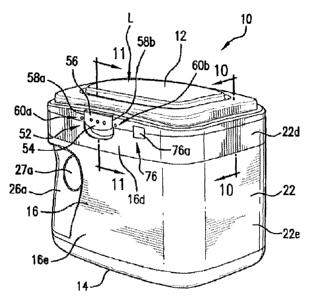
geometry that is shaped to be congruent with the junctions or corners 50a,
50b,
50c, and 50d, formed by the junctions between the front wall 16 and the first
side
wall 20 and the bottom wall 14, the front wall 16 and the second side wall 22
and
the bottom wall 14, the rear wall 18 and the first side wall 20 and the bottom
wall
14, and the rear wall 18 and the second side wall 22 and the bottom wall 14,
respectively. The corners or junctions 50a, 50b, 50c, and 50d are shown in
FIG. 9
and are also evident from the exterior views of FIGS. 1, 2, and 5 - 8. The
shape
22
CA 02892925 2015-05-28
of the corners 50a, 50b, 50c, and 50d and the shape of the rim 36a of the bowl
36
of the scoop 32 enable the maximum quantity of product to be removed from the
container 10 by the scoop 32, without having to invert or to turn the
container 10
over to pour out the product.
[00107] As shown in FIG. 9, the corners 50a, 50b, 50c, and 50d have a
particular cross-sectional geometry and are preferably rounded, and are more
preferably formed with the radius of each corner 50a, 50b, 50c, and 50d being
approximately equal to the radius of the rim 36a of the bowl 36 of the scoop
32.
In an alternative embodiment (FIG. 32, corner 50f), the corners can have other
shapes, e.g., the corners 50a, 50b, 50c, and 50d and the corners or junctions
between the bottom wall 14 and the walls 16, 18, 20, and 22 can meet to form
right angles. The rim 36a of the bowl 36 can be formed with a portion of the
rim
having a right angle (see, e.g., FIGS. 32 & 33) that is generally congruent to
that
of the contemplated right angles of the corners or junctions between the walls
16,
18, 20, and 22 themselves and between the bottom wall 14 and the walls 16, 18,
20, and 22.
1001081 In still another embodiment (see exemplary scoop variation in FIG.
33),
the corners 50a, 50b, 50c, and 50d can have three sides, with two 1200 angles
forming each corner. In these alternative embodiments, the bowl 36 of the
scoop
32 would have a shape and/or a rim portion 36c (FIG. 33) that would be
congruent
with the shape of each corner 50a, 50b, 50c, and 50d. See also, for example,
the
analogous variation of a right angle scoop rim and wall junction illustrated
in FIG.
32. In further optional or preferred arrangements, the walls 16, 18, 20, 22
join the
bottom wall 14 to also have the particular cross-section geometry and are also
more preferably rounded, and are even more preferably formed with radius
similar
to that of each corner 50a, 50b, 50c, 50d to be approximately equal to the
radius
and/or to have a shape congruent to that of the bowl 36 of the scoop 32. In
any of
these illustrative embodiments, those skilled in the art may comprehend from
the
discussion elsewhere herein that the material used to form the container 10
and
the scoop 32 and/or the bowl 36 of the scoop may be of a flexible polymeric
material that can enable the rim 36a of the bowl 36 to flex and/or to deform
either
a small or a more generous amount. In this way the cross-sectional geometry of
the rim 36a can, during use, be biased against the junctions or corners in a
way
23
CA 02892925 2015-05-28
whereby the rim 36a more readily conforms to the particular cross-sectional
geometry to maximize the ease of removal of the contents from the hollow
interior
space "H". In FIGS. 32 and 33 examples of congruently shaped bowls 36 are
shown. In FIG. 32, the rim has a portion 36b arranged to have a right angle
that
can conform to and be congruent with a corner 50f of a container having a
similar
right angled wall junction. In FIG. 33, the rim has a multi-angled rim 36c
wherein
multiple obtuse angles are formed to be congruent with a similarly shaped wall
junction (not shown, but similar in concept to wall junction 50f of FIG. 32).
1001091 The shape of the bottom wall 14 of the container 10 and the shape of
the top wall 12 of the container 10 can be designed to enable a plurality of
containers 10 to be stacked, one upon another, such as, for example, on a
shelf in
a grocery store. It is preferred that the shape of the perimeter of the bottom
wall
14 of the container 10 be substantially similar to the shape of the perimeter
of the
top wall 12 of the container 10. The top wall 12 can be flat or contoured and
the
bottom wall 14 can be flat or contoured. Generally, if the top wall 12 is
contoured,
the bottom wall 14 must also be writoured in such a manner as to be
substantially
congruent with the top wall 12, so that a plurality of containers 10 can be
stacked
one on top of another.
[00110] However, so long as the lid "L" is flat, the containers 10 will be
stackable
even if the bottom wall 14 of the container 10 is not flat, provided that the
bottom
wall 14 of the container 10 is designed so that the top wall 12 of the
container 10
remains in a horizontal orientation relative to a horizontal shelf. In FIGS.
1, 2, 4,
10 ¨ 12, and in FIGS. 16, 19, 30 - 31, and 34 - 36, it can be seen that the
top wall
12 (or also top wall 212) of the container 10 (or the container 210) is convex
in
shape. Accordingly, for the embodiment shown in FIGS. 1 and 2, the bottom wall
14 of the container 10 is preferably concave in shape, so that a plurality of
containers 10 can be stacked one upon another.
[001111 The rectangular shape of the container 10, in combination with the
recesses 26a and 26b for gripping, enables the user to hold the container 10
with
one hand, while using the scoop 32 with the other hand. The shape of the
container 10 enables ease of access to the product during the act of removing
the
product from the container 10 by means of the scoop 32.
24
CA 02892925 2015-05-28
1001121 The shape of the container 10 enables the lid "L" to be securely
fitted to
the upper portions 16d, 18d, 20d, and 22d, of the front wall 16, the rear wall
18,
the first side wall 20, and the second side wall 22, respectively, of the
container
10.
[00113] Referring now to FIGS. 1, 4, and 11, (and to FIGS. 16 and 19 for
illustrations of later discussed embodiments and variations thereto) a
container-
locking feature 52 associated with the lid "L" and the front wall 16 enables
the lid
"L" to be securely, and robustly fitted to the edges of the upper portions
16d, 18d,
20d, and 22d, of the front wall 16, the rear wall 18, the first side wall 20,
and the
second side wall 22, respectively, of the container 10 over a range of the
dimensional tolerances of the container 10. The container-locking feature 52
comprises a latch 54 having a tab or flap 56, a first edge 58a and a second
edge
58b.
1001141 A first bridge 60a and a second bridge 60b project from the first edge
58a and the second edge 58b of the latch 54, respectively. The first bridge
60a
comprises a small stem 62a at one end of which is a knob 62b; the second
bridge
60b comprises a small stem 64a A one end of which is a knob 64b. The knobs
62b and 64b and portions of the small stems 62a and 64a fit into small
recesses
(not shown) in the exterior surface "Le" of the lid "L", which small recesses
are
congruent with the bridges 60a and 60b, and are prevented from being removed
from the recesses (not shown) by friction, until the latch 54 is opened for
the first
time. The function of the bridges 60a and 60b is to indicate any tampering
with
the latch 54. Referring now to FIG. 11, the tab or flap 56 of the latch 54 is
attached to the front wall 16 by a hinge 68, typically a living hinge, which
connects
the tab or flap 56 to an element 70 projecting from the exterior major surface
16b
of the front wall 16.
[00115] When the latch 54 is in a non-tampered state, the first bridge 60a and
the second bridge 60b retain their integrity. Prior to being used, the tab or
flap 56
is maintained in a closed position by gripping a keeper 72, which is formed
into a
recessed portion 74 of the exterior major surface 16b of the front wall 16.
When
the latch 54 is opened by rotating the tab or flap 56 from its initial
unopened
position to a second position away from the keeper 72, the pull force breaks
the
small stems 62a and 64a, thereby allowing the lid "L" of the container 10 to
be
CA 02892925 2015-05-28
lifted upwardly so that the lid "L" can rotated about the hinge 24 (see FIG.
2) to
enable the user to obtain access to the interior of the container 10.
[00116] If the user finds that extremely little pulling force is required to
break the
small stems 62a and 64a of the bridges 60a and 60b, respectively, the consumer
will suspect that tampering with the latch 54 has taken place. After the small
stems 62a and 64a are broken, the knobs 62b and 64b help to retain the
remaining portions of the broken bridges 60a and 60b in the recesses in the
exterior surface "Le" of the lid "L". In order to close the lid "L" of the
container 10
after a given use, the lid "L" is rotated downwardly so that the edges of the
lid "L"
come into contact with the edges of the upper portions 16d, 18d, 20d, and 22d
of
the front wall 16, the rear wall 18, the first side wall 20, and the second
side wall
22, respectively, of the container 1.0, whereupon the tab or flap 56 of the
latch 54
can grip the keeper 72 to maintain the container 10 in a closed position until
the
user desires to open the container 10 at a later time. Even more preferably,
the
latch 54 engages and disengages with a click that can be perceived both by
tactile
as well as auditory feedback, which give the user additional cues regarding
the
open or closed state of the lid "L" and the contained 10.
1001171 As shown in FIGS. 1 & 16, a tamper-indicating seal 76 can be adhered
to the front or another place on the container to present evidence of
tampering,
damage, or other circumstance. In FIG. 1, the tamper seal 76 is affixed to
wall 16
and the lid "L" of the container 10 to provide a visual indication as to
whether the
container 10 has been opened prior to being sold. In one embodiment, the
tamper-indicating seal 76 comprises a backing 76a adhered to a layer of
adhesive
(not shown). The backing 76a can be a sheet of tearable paper or tearable
polymeric material. The adhesive can be a moderately to highly aggressive
adhesive. The tamper seal 76 can be positioned in a number of equally
effective
locations, including for purposes of example without limitation, across the
interface
between the lids and walls as well as in appropriate locations across the the
contemplated assemblies of collars and lids.
[00118] It is preferred that a score line or a line of perforations be present
in the
backing 76a of the tamper-indicating seal 76 at the line where the lid "L"
meets the
upper portion 16d of the front wall 16 of the container 10. An attempt the
open the
container 10 will result in tearing ,the backing 76a along the score line or
the line of
26
CA 02892925 2015-05-28
perforation, thereby indicating visually an unauthorized attempt to open or an
actual opening of the container 10.
[00119] The dimensions of the container 10 and the components thereof are not
critical. However, for the purpose of illustration, typical dimensions of the
various
components can be as follows:
[00120] Top wall 12 and bottom wall 14: 4 in. to 5 in. x 5.5 in to 6.5 in.
[00121] Front wall 16 and rear wall 18: 5.5 in. to 7.5 in. x 5.5 in. to 6.5
in.
[001221 First side wall 20 and second side wall 22: 4 in. to 5 in. x 5.5 in.
to 7.5 in.
[00123] Volume of container 10 to contain powder weights of: 10 to 60 oz.;
more
typically 20 to 40 oz.; for example 23 oz. to 34 oz.
[00124] There are numerous methods of making the container 10 described
herein. However, in order to facilitate mass production of containers having a
variety of volumes, the container 10 can be assembled in a variety of equally
suitable ways and by using any of a number of effective and optionally
preferred
mechanisms. For purposes of illustration without limitation, the exemplary
configurations shown here contemplate friction-fit, clip, and similar types of
lid-
collar-container assembly devices. Such examples can be seen in the various
figures including in FIGS. 4 ¨ 8, and later in other variations and
modifications of
the embodiments of the invention depicted in FIGS. 16 - 28.
[00125] Referring now to FIGS. 4, 5, 6, 7, and 8, a tub-shaped receptacle 80
comprising the bottom wall 14, the lower portion 16e of the front wall 16, the
lower
portion 18e of the rear wall 18, the lower portion 20e of the first side wall
20, and
the lower portion 22e of the second side wall 22 can be provided by a
supplier.
The lower portion 16e of the front wall 16, the lower portion 18e of the rear
wall
18, the lower portion 20e of the first side wall 20, and the lower portion 22e
of the
second side wall 22 typically comprise about from about 60% to about 90% of
the
height of the aforementioned front wall 16, rear wall 18 first side wall 20,
and
second side wall 22, respectively.
[00126] An assembly 82 comprising a collar 84 and the lid "L" (alternatively
referred to herein as "collar/lid assembly 82") can be provided by a supplier.
The
collar/lid assembly 82 comprises the top wall 12, the upper portion 16d of the
front
27
CA 02892925 2015-05-28
wall 16, the upper portion 18d of the rear wall 18, the upper portion 20d of
the first
side wall 20, and the upper portion 22d of the second side wall 22. The upper
portion 16d of the front wall 16, the upper portion 18d of the rear wall 18,
the
upper portion 20d of the first side wall 20, and the upper portion 22d of the
second
side wall 22 typically comprise from about 10% to about 40% of the height of
the
front wall 16, rear wall 18 first side wall 20, and second side wall 22,
respectively.
[00127] The ratios for the lower portion 16e of the front wall 16, the lower
portion
18e of the rear wall 18, the lower portion 20e of the first side wall 20, and
the
lower portion 22e of the second side wall 22 and the ratios for the upper
portion
16d of the front wall 16, the upper portion 18d of the rear wall 18, the upper
portion 20d of the first side wall 20, and the upper portion 22d of the second
side
wall 22 primarily depend upon the volume of the container 10, which in turn
depends upon the volume of the tub-shaped receptacle 80. The size of the
assembly 82 of the collar and lid essentially remains constant, but the volume
of
the tub-shaped receptacle 80 varies to provide containers of various volumes.
[00128] Various attachment methods for combining the collar and lid assembly
with the receptacle are contemplated by the invention, and combinations and
variations may be found to be equally suitable and can be interchanged as
needed as can be better understood with reference to FIGS. 3 - 4, 10 - 13, and
16
- 36. Referring first to FIGS. 3 - 4 and 10 - 13, those skilled in the art
will see
that in one variation of the preferred embodiments of the invention, each
corner
84a, 84b, 84c, and 84d of the collar 84 has at least one guide fin 86a, and
preferably two guide fins 86a, 86b, to properly align the collar 84 with the
tub-
shaped receptacle 80. The tub-shaped receptacle 80 is made up of the bottom
wall 14 and those portions of the front wall 16, the rear wall 18, the first
side wall
20, and the second side wall 22 that are not made up of the upper portions
16d,
18d, 20d, and 22d of the front wall 16, the rear wall 18, the first side wall
20, and
the second side wall 22, respectively, which upper portions 16d, 18d, 20d, and
22d make up the collar 84.
[00129] The collar 84 is joined to the tub-shaped receptacle 80 by aligning
the
guide fins 86a, 86b in each corner 84a, 84b, 84c, and 84d of the collar 84
with the
corners 80a, 80b, 80c, and 80d located at a sealing flange or rim 88 of the
tub-
shaped receptacle 80 and press-fitting the collar 84 to the tub-shaped
receptacle
28
CA 02892925 2015-05-28
80. The sealing flange or rim 88 terminates in an internal edge 89 that
defines an
opening to the hollow interior space "H".
1001301 The guide fins 86a, 86b in each corner 84a, 84b, 84c, and 84d of the
collar 84 snugly fit into a groove 90 running around the exterior periphery of
the
tub-shaped receptacle 80. After the collar 84 is joined to the tub-shaped
receptacle 80, the tamper-indicating seal 76 is applied to the front wall 16
and the
lid "L" of the container 10. The later described interlocking and lid, collar,
receptacle combining features illustrated in FIGS. 16-29 are also contemplated
for
use in the instant embodiments and modifications thereto. The instant
described
attachment features are similarly susceptible for use with the later described
embodiments discussed below.
1001311 The position of the substantially moisture-impervious, oxygen-
impervious seal 28 inside of the container 10 is a matter of choice. In one
embodiment, the substantially moisture-impervious, oxygen-impervious seal 28
can be applied directly to the sealing flange or rim 88, which is an attach
surface
running around the periphery of the tub-shaped receptacle 80 by means of an
adhesive, typically a heat-sealable adhesive. See FIGS. 14, 20, 23, and 26. In
another embodiment, the seal 28 can be applied to the interior walls 16a, 18a,
20a, and 22a of the front wall 16, the rear wall 18, the first side wall 20,
and the
second side wall 22, respectively, of the container 10 at a position lower
than the
rim 88 running around the periphery of the tub-shaped receptacle 80 of the
container 10, such as, for example, at a point approximately midway or lower
on
the groove 90 that runs around the periphery of the tub-shaped receptacle 80.
This embodiment may call for custom attaching equipment, but may be desirable
because movement of granular product into cracks and fissures between the tub-
shaped receptacle 80 and the collar 84 can be reduced.
[00132] The use of a living hinge or a mechanical hinge for pivotally and/or
hingedly joining the lid "L" to the collar 84 is also a matter of choice.
Referring
now to FIGS. 2 and 3, in one embodiment employing a mechanical hinge 100
(see FIG. 3 and also FIGS. 16-19, 24, and 29 - 31), pins can be molded into
projections 102a, 102b, respectively, rising upwardly from the upper rear edge
104
of the collar 84. These projections 102a, 102b can be molded so as to be flush
with the exterior surface of the collar 84. FIG. 3 shows the projection 102a
in
29
CA 02892925 2015-05-28
greater detail. The projection 102a has a pin 106a formed thereon by molding.
The projection 102b also has a pin formed thereon by molding.
[001331 While the pin on the projection 102b is not shown, it is the mirror
image
of the pin 106a. Sockets can be formed in the lid "L" to receive and retain
the pins
of the projections 102a, 102b. FIG. 3 shows the socket 108a for receiving the
pin
106a. While the socket for receiving the pin of the projection 102b is not
shown, it
is the mirror image of the socket 108a. The lid "L" can be molded in such a
manner that the sockets are not visible from the exterior of the container 10.
In
addition, the lid "L" can be molded in such a manner that recesses 110a, 110b
are
provided therein so that the pin-bearing projections 102a, 102b can be flush
with
the exterior surface of the lid "L".
[001341 In addition, the shape of the rear edge 112 of the lid "L" and the
shape
of the upper rear edge 104 of the collar 84 can be designed in such a manner
that
when the lid "L" is fully opened, the lid "L" will be supported by the upper
rear
edge 104 of the collar 84 at a specified angle, such as, for example, 1200, so
that
the user can obtain access to the contents of the container 10 without being
restricted by the presence of the lid "L". In the particular embodiment shown
in
FIG. 2, two projections, each projection bearing a pin, and two sockets can be
used.
[001351 Any and all of the preceding preferred embodiments and the
modifications and variations thereof may be incorporated in whole or in part
to
many additionally contemplated configurations of the container 10. Similarly,
the
many next to be discussed adaptations, variations, and modifications, are
contemplated for use with all of the preceding embodiments, alone, in part,
and in
combination. With continued reference to FIGS. 1 ¨ 15, and referring now also
to
FIGS. 16 through 22, another configuration of a sealing container according to
the
invention is shown and identified generally by reference numeral 210, which is
also susceptible for use and to incorporate any or all of the previously
described
features, components, and modifications and variations of the invention.
[001361 As with other embodiments, the sealing container 210 includes a top
wall 212, a bottom wall 214, a front wall 216, a rear wall 218, a first side
wall 220,
and a second side wall 222, which together define an interior space "I".
Similar to
other embodiments of the invention, the walls are defined with interior and
exterior
CA 02892925 2016-04-06
surfaces and upper and lower portions. The front wall 216 includes an interior
surface 216a, an exterior surface 216b, an upper portion 216d, and a lower
portion 216e. The rear wall 218 has an interior surface 218a, an exterior
surface
218b, an upper portion 218d, and a lower portion 218e. The first side wall 220
defines an interior surface 220a, an exterior surface 220b, an upper portion
220d,
and a lower portion 220e. The second side wall 222 includes an interior
surface
222a (not shown), an exterior surface 222b, an upper portion 222d, and a lower
portion 222e.
[001371 With reference now also to FIGS. 29 ¨ 31 and 34 - 36, it may be
understood that a lid of the container 210 may be a separate component, part
of
an assembly, and may also include and be forrned as a part of the top wall 212
and the upper portion 216d of the front wall 216, the upper portion 21Bd of
the
rear wall 218, the upper portion 220d of the first side wall 220, and the
upper
portion 222d of the second side wall 222.
(001381 An alternative configuration of the lid depicted here is referred to
generally by reference character "D". The lid "D" has an interior surface,
which
will hereinafter be referred to by the reference character "Di" (FIGS. 30-31).
The
lid also has an exterior surface, which will hereinafter be designated by the
reference character "De". The lid "D" may also be shaped to cooperate with the
features of the bottom wall 214 to enable stacking of the containers 210 as
described in earlier descriptions of the embodiments of the invention. As
contemplated for use with this and the other previously and later described
embodiments of the invention, the lid "D" is shown as a separate component
that
is hingedly, rotatably, and/or pivotally connect to the containers of the
invention.
Even more preferably, the lid "D" may be connected to the later described
collar
for incorporation into the variations of the embodiments of the invention.
[00139] An alternative hinge 224 may attach the lid "D" to the upper portion
218d of the rear wall 218. While any of the previously described hinges may be
incorporated in the embodiment contemplated by sealing container 210, the
modified mechanical hinge 224 as shown in the various figures may be
incorporated to replace or work in combination with any of the preceding
hinges.
[001401 The modified variations of the sealing container 210 may also
incorporate gripping features such as those previously described and as shown
in
FIGS. 16 ¨ 19 and 21, wherein the front wall 216 has a recess 226a arranged to
31
CA 02892925 2015-05-28
enable grasping or gripping of the container 210 by a left thumb of the user.
The
rear wall 218 also has a recess 226b positioned to facilitate gripping of the
container 210 by the fingers of the ieft hand of the user. The recess 226a can
further have an additional recess 227a to indicate the precise location in the
recess 26a for the placement of the thumb of the user. The recess 227a is
smaller in area than the recess 226a. The recess 227a is preferably circular
in
shape, but other shapes are also acceptable. The recess 226b can further have
an additional recess 227b to indicate the precise location in the recess 226b
for
the placement of the desired finger of the user. The recess 227b is smaller in
area than the recess 226b. The recess 227b is preferably circular in shape,
but
other shapes are also acceptable. In FIGS. 16-19, the recesses 226a and 226b
are positioned adjacent to the first side wall 220 of the container 210.
However,
variations (not shown) will incorporate the recesses to be complemented by
additional and/or replacement recesses proximate the opposite second side 222.
[00141] With reference now also to FIGS. 13, 20 ¨ 21, 23, and 26, the
substantially moisture-impervious, oxygen-impervious seal 28 having a pull tab
28a is affixed to a position proximate to edges of the upper portions 216d,
218d,
220d, 222d of the walls 216, 218, 220, 222 as explained in connection with
previously described variations of the preferred embodiments of the invention.
[00142] Referring now to FIGS. 30 - 33, attached to the interior surface "Di"
of
the lid "D" is the previously described scoop holder 30 and scoop 32. A
variation
to earlier embodiments of the scoop 32 includes a stiffened handle 34 having a
stiffener 34b integrally formed thereon. Additionally, the first bracket bowl
cover
30a of the holder 30 may be projected outward to a predetermined maximum
dimension whereby multiple scoops 32 having different volumes of bowl 36 can
be
incorporated to maximize convenience when dispensing different volumes of the
contents of the containers 10, 210.
[00143] In another preferred or optional variation to any of the preceding
embodiments, and with reference to FIGS. 16 ¨ 19, 20 ¨ 22, and 26, the
container
210 may be formed from a tub-shaped receptacle 280 similar in construction to
earlier described embodiments but may also incorporate upper portions 16d,
18d,
20d, 22d of walls 16, 18, 20, 22 having an upper end 282. The upper end 282
32
CA 02892925 2015-05-28
defines a sealing flange 284 having an internal edge 286 that defines an
opening
to the interior space "I".
[00144] In further preferred arrangements, the impervious seal 28 is seated
around the upper end 282 to close' and seal the opening and is removably
affixed
to the sealing flange 284. To improve accuracy and convenience during assembly
and placement of the impervious seal 28 on the sealing flange 284, an optional
snap bead 288 (FIGS. 23 & 26) may be formed on the upper end 282 below the
sealing flange.
[00145] Such a snap bead 288 can be used as a shelf and/or seat that contacts
the edges of the unattached impervious seal around the periphery of the
container
to keep the impervious seal 28 in place and centered so that it can be
attached
with adhesive, heat sealing, or another means.
[00146] In the past, many containers were improperly sealed due to incorrect
placement of the seal before an adhesion step glues, melts, or otherwise
affixes
the impervious seal 28 to the sealing flange 284. Additional variations of any
of
the embodiments of the invention may also include assembly improving features
such as one or more engagement recesses or indentations 290 defined laterally
separated by strengthening bridges 292, a lower seat rib 294, and an upper lug
ledge or downwardly facing top surface 296.
[00147] The spaced apart bridge 292 arrangement imparts improved strength
and rigidity capabilities to the upper end 282 of the receptacle 280, which,
in turn,
improves the crippling strength of the container and the rigidity of the upper
end
282 when the collar 300 is fitted together with the receptacle 280. Further
preferred or optional variations to any of the preceding embodiments may
include
a modified collar 300 that can be'oest illustrated with specific reference to
FIGS.
16 ¨ 21, 24, - 28. The collar 300 may be formed with a substantially J-shaped
and/or U-shaped cross-sectional configuration. With reference to the various
figures, it can be seen that the exemplary collar 300 has an upside-down U-
shape
and/or J-shape.
[00148] The collar 300 includes an exteriorly or outwardly facing long wall
302
that extends upward to join a substantially rounded portion 304 that may have
an
increased thickness if needed for stiffening the collar 300. The small
relative
radius of the J-shaped section shown in the illustrations enables excellent
stress
33
CA 02892925 2016-04-06
distribution and force load path communication by way of a higher cross-
sectional
moment of inertia, which results in a stiffened and stronger collar. The long
wall
302 also forms a part of the upper portions 216d, 218d, 220d, 222d of the
walls
216, 218, 220, 222.
[00149] The rounded portion 304 extends further and downwardly to form an
interiorly or inwardly facing short wall 306. More preferably, the rounded
portion
304 will be formed to have a lip seat 305 that enables alignment and improved
engagement of the outermost edge 348 of lid ''D" when it is closed onto the
collar
300. See, for example, FIGS. 25 - 26.
[00150] The collar may also preferably incorporate engagement lugs or flex
clips
310 that are laterally spaced apart to correspond to the lateral spacing of
the
indentations 290. The flex clips 310 will incorporate an upwardly facing
surface
and/or a retainer face 312 and may also optionally include a stiffening rib
314.
During assembly, the collar 300 will be centered and aligned by the flex clips
310
and thus arranged to fit on, overcap, andfor be installed upon the upper end
282
of the tub-shaped receptacle 280 so that the flex clips 310 will bend
outwardly
slightly as the collar 300 descends over the upper end 282.
[00151] Once the flex clips 310 are moved into a juxtaposition relationship
with
the indentations 290, the flex clips 310 return to the nominal orientation and
snap
into position so that the retainer faces 312 contact the downwardly facing top
surfaces 296 to interlock the collar 300 onto the receptacle 280. In this way,
the
collar 300 is captured and in a friction-fit and flex clip 310 engaged
relationship
with the tub-shaped receptacle 280. A bottom end 303 (FIG. 26) of the
outwardly
facing long wall 302 will generally come into contact with and rest against
the
lower seat rib 294 of the receptacle 280, which in combination with the other
features of the invention enables increased strength and rigidity.
[00152] The laterally spaced apart indentations 290 and bridges 292 establish
a
well-distributed load interface between the collar 300 and the receptacle 280
having good rigidity properties when subjected to nominal applications.
Additionally, the laterally spaced apart bridges 292 have been found to
greatly
improve the crippling strength of the assembled collar 300 and receptacle 280
combination. These features combine with the capture and retain capability of
the
flex clips 310 to hold the collar 300 to the upper portion or upper end 282 of
the
34
CA 02892925 2015-05-28
container 210 and thereby laterally stabilize the collar 300 so that the
collar 300
remains in a substantially fixed position relative to the container opening.
[001531 In additionally preferred and optional modifications to any of the
embodiments of the invention, the plurality of indentations 292 and the
plurality of
spaced apart flex clips 310 are further positioned to be oppositely paired
across
the receptacle 280 to establish fore load coupling between the pairs to
increase
rigidity and structural stability of the sealable containers 10, 210 when the
collar
300 is fitted onto the upper end or portion 282. This opposite or confronted
pairing establishes a series of coupled moment arm vectors having a distance
equal to the diameter, width, and/or depth dimension of the container, which
greatly improves load distribution across the container 10, 210 and increase
the
structural stability thereof.
1001541 Furthermore, it has been found that these novel features have resulted
in an unexpected configuration that overcomes otherwise unacceptable tolerance
anomalies and part mismatch between the collar 300 and the upper portion or
upper end 282 of the receptacle 280, which greatly reduces rejected parts and
which significantly lowers manufacturing costs. More specifically, it is
optionally
preferred to incorporate the upwardly facing surfaces or retainer lugs 312 to
be
dimensionally smaller than the downwardly facing surfaces or upper lug ledges
296 of the receptacle 280.
[00155] In one aspect, this dimensional arrangement can enable the the
retainer
lugs or upwardly facing surfaces 312 to move within the engagement recesses or
indentations 290 and about the upper lug ledges or downwardly facing surfaces
296. This can enable the combination of these components to absorb
dimensional tolerance errors and enable the collar to fit around the upper
portion
of the container. Even more preferably, at least one of the collar 300 and the
upper end or portion of the walls 282 are formed from a substantially flexible
material such as a polymeric material like polyethylene or polypropylene to
enable
at least one of the collar and the upper portion of the walls to flex.
[00156] Flexibility enables absorption of dimensional tolerance errors, which
enables the collar to fit around the upper portion of the container. Also,
this can
enable at least one of the collar 300 and the upper portion or end 282 of the
walls
to flex to accommodate shape mismatch between at least one of the collar and
CA 02892925 2016-04-06
the upper portion of the walls to enable the collar to fit around the upper
portion of
the walls.
[001571 When assembled, the collar 300 and the upper end 282 of the
receptacle 280 form a subcollar space 320 (FIG. 26). In other optionally
preferred
arrangements of the collar 300, a raised seat 325 may be formed on the
inwardly
facing short wall 306 to establish a greater thickness of the short wall 306
for
applications where other elements may be attached to the short wall. In one
particularly preferred optional embodiment, a flexible, polymeric gasket or
seal
330 may be affixed to the short wall 306, and more preferably may be attached
to
the raised seat 325. Even more preferably, the flexible gasket 330 may be
either
affixed by adhesive to the short wall 306 and/or the raised step 325, or may
be
directly injection molded onto the short wall 306 and/or the raised step 325.
(00158) In this particular example, the raised seat 325 may be also
thermoformed as the collar300 is formed or molded, or the raised seat 325 may
be formed in a second and/or separate thermoforming step that may occur before
the gasket 330 is attached. Additionally, the raised seat 325 may be formed in
the
step at the same time or nearly the same time the gasket 335 is attached. The
flexible gasket preferably extends inwardly and interiorly with an internal
edge
332.
[00159] Preferably, the flexible gasket is dimensioned to project inwardly or
interiorly and to removably rest against the sealing flange 284 as depicted in
FIGS. 23 and 28. More preferably, the flexible gasket 330 projects slightly
downwardly to to be biased against the sealing flange 284 for an improved
sealing
configuration. Even more preferably, the flexible gasket 330 extends
interiorly or
inwardly to project the internal edge 332 beyond the internal edge 286 of the
sealing flange 284. With this arrangement, the subcollar space 320 is sealed
from
the interior space "I" to prevent contents of the interior space "I" from
entering the
subcollar space 320. If such is not prevented, an inconvenience is presented
wherein contents that have spilled into the subcollar space 320 may further
spill
outside the container 210 by moving through any interstice that may exist
between
the lower end of the outwardly facing long wall 302 and the lower seat rib 294
(FIG. 26).
36
CA 02892925 2015-05-28
[00160] With specific reference to FIGS. 20, 23, and 26, those skilled in the
art
may comprehend that the impervious seal 28 is removably sandwiched between
the gasket 330 and the sealing flange 284 (and beneath the gasket 330). When
pull tab 28a is grasped and the impervious seal 28 is removed to expose the
contents of the container 210, the flexible gasket 330 flexes away from its
rest
position against the sealing flange 284 to enable removal of the impervious
seal
28. As the impervious seal 28 is removed, the flexible gasket 330 returns to
its
rest position against the sealing fL-nge 284. This configuration permits a
more
robust hermetic, impervious seal 28 for distribution to the end user, who
removes
the seal 28 upon first use, yet still enjoys the benefits of the sealing wall
and
gasket 330 to prevent or minimize content leakage.
[00161] Many possible types of material are suitable for use in fabricating
the
gasket 330. One illustrative example of a suitable material includes a thin
polymeric material such as a thermo-plastic elastomer having a durometer
strength of approximately 50 or other similar Shore A grade material so that
the
impervious seal 28 may be easily removed while the flexible gasket is still
able to
retain some shape memory so that it returns to a biased, sealing rest position
against the sealing flange 284. For optionally preferred applications, Shore A
grade material such as a Santoprene and similar compounds have been found to
be satisfactory and can be readily thermoformed or injection molded directly
onto
the inwardly facing short wall 306 and/or the raised seat 325.
[00162] In other equally preferred and optional variations to any of the
embodiments of the invention, the gasket 330 may be integrally formed as part
of
the collar 300 wherein the gasket 330 is a flap of flexible and thin material
that is
molded from and that extends from the interior surface of the collar 300. In
this
contemplated modification to any of the embodiments, among other options, the
raised seat 325 can be formed to project inwardly as the gasket 330.
[00163] Other modifications to the preferred embodiments of the containers
10,
210 may incorporate a modified removable lid such as lid "D" shown in FIGS. 30
through 36. The new variation contemplated by removable lid "D" preferably
defines the interior surface "Di" to be sized to cover and seal the opening to
the
interior space "I" when the lid "D" is closed. The lid "D" incorporates a
sealing wall
340 depending from its interior surface "Di" and that projects toward the
sealing
37
CA 02892925 2015-05-28
flange 284 and which is centered and aligned by including optionally preferred
alignment and/or wall ribs 341 (FIG. 30 - 31).
[00164] With this configuration, when the lid "D" is closed on the collar 300
to
seal the container 210, the gasket 330, the sealing wall 340, and the sealing
flange 284 are dimensioned and positioned so that the sealing wall 340
depresses
and biases the flexible gasket 330 against the internal edge 286 of the
sealing
flange 284 to seal the subcollar space 320 from the container interior "I".
The
flexibility and shape memory and strength of the flexible gasket 330 must also
withstand repeated opening and casing of the lid "D" and biasing and unbiasing
of
the gasket 330 by the moving sealing wall 340, so that the flexible gasket
remains
biased and at rest against the sealing flange 384. These optionally preferred
variations of the position of the sealing wall 340 are contemplated as shown
with
the solid and dashed line representations of sealing wall 340 shown in FIG.
26.
[00165] In any of the possibly preferred positions of sealing wall 340, the
length
and/or location of the downwardly projecting lower edge 342 is adjustable as
preferred so that the lower edge 342 can, when lid "L" or "D" is in the closed
position, terminate just above, bias against, and/or bias against and depress
gasket 300 downward so that gasket 330 is in turn biased against sealing
flange
284. In further alternative variations to the preceding embodiments, the
flexible
gasket 330 may be attached to the sealing wall 340 instead of the raised seat
325.
In further variations, a second gasket (not shown) may be attached to the
sealing
wall 340 either alone and/or in addition to and to cooperate with the flexible
gasket
330 that is attached to the raised seat 325.
1001661 In still other modifications to any of the variations of the preferred
embodiments, the sealing wall 340 may be implemented to function with or
without the use of a gasket 330 and may include a funneled lower edge 342 such
as those shown in FIGS. 27 and 28. In FIG. 27, the funneled lower edge 342
includes an inwardly curved and/or inwardly tapering sealing wall 340a. In
FIG.
28, the funneled lower edge 342 incorporates an inwardly slanted and/or
tapering
sealing wall 340b. A combinatior 3f a slanted and/or curved and tapering wall
340a and 340b is also contemplated, which can be used either alone and/or in
combination with the flexible and/or integral gasket 330 illustrated elsewhere
herein. Particularly in embodiments not using the gasket 330, the sealing wall
340
38
CA 02892925 2015-05-28
may be dimensioned so that when the lid "D" is closed, the sealing wall 340
remains inward of the sealing flange 284.
[001671 In further preferred variations to the preceding embodiments, the lid
"D"
more preferably includes a substantially domed central section 344 that has
dimensions less than the sealing wall 340. The domed central section is joined
to
the lid either by the sealing wall, by an angled wall 346, and by a
combination
thereof, wherein the angled wall 346 tapers from the domed central section
down
to the interior surface "Di" proximate to the sealing wall 340 (FIGS. 34 ¨
36). As
with earlier discussed embodiments and modifications thereto, the modified lid
"D"
is configured with an overall shape that cooperates with the shape of the
bottom
wall 14 to enable easy stacking of the containers 210. Proximate to the
junction of
the sealing wall 340 and the angled tapered wall 346, a collar engagement
member projects generally downward to a lip edge 348 that seats into and
engages with lip seat 305 of the collar 300, so that when the lid "D" is
closed, a
more rigid and tightly closed assembly of collar 300 and lid "D" is
established.
[00168] In the adaptation wherein the substantially domed central section 344
is
connected only by the sealing wall 340, essentially the tapered angled wall
346
merges with the sealing wall 340 to have an angle relative to the vertical
direction
of approximately 90 degrees. The tapered angled wall 346 is in other
variations
arranged to have an angle relative to a vertical direction of between
approximately
10 and approximately 75 degrees, and preferably between about 15 and 60
degrees, and more preferably between about 25 and 45 degrees, and even more
preferably approximately 30 degrees. The substantially domed central section
344 extending to the sealing wall preferably is dimensioned to define an area
between approximately 20 percent and approximately 80 percent smaller than an
entire area defined by the removable lid. Further, the substantially domed
central
section 344 projects upwardly with a height dimension that is between
approximately 10 percent and approximately 60 percent of a cumulative lid
height
dimension; ideally to house the scoop above the impervious seal 28.
[00169] These variations of the substantially domed lid have been found to be
of
significance when the sealable cbritainer 210 is in use with powdered contents
contained therein. When the container 210 is jostled about and inverted during
transit, such as when being transported in the diaper bag of a parent or when
39
CA 02892925 2015-05-28
being shipped from a warehouse to a retail location while being upside-down
and
inverted, the powdered contents may collect and become packed into a small
mountain resting against portions of the interior surface "Di" of the lid "D".
When
such a disoriented container is righted, the angled wall 346 and the sealing
wall
340 cooperate to more readily and effectively disengage the collected and/or
packed contents from the interior surface "Di" of the lid "D" so that the
packed or
collected contents fall freely down into the interior space "I" of the
container 210.
[00170] Many factors can contribute to creating an inconvenient accumulation
of
powder packed into the lid "L" or "D". Those skilled in the relevant arts
often
characterize the flowability of a powdered material to be a function of many
variables that include particle size'and distribution, cohesivity, static
charge,
surface coating, ability to recover from packing or compaction, temperature,
humidity, aeration, transportation experience, and container surface effects.
Even
with so many powder flowability characteristics confronted the manufacturer
and
the user of container according to the principles of the invention, it has
been found
that the new and novel angled and/or tapered wall 346 of the invention, alone
and
in combination with the other powder control features described herein, have
established a new and previously unseen means of directing powdered contents
back into the interior space "H" upon righting of the containers 10, 210.
[00171] The arrangement of the flexible gasket 330 biased at rest against the
sealing flange 284 further cooperates to mostly if not entirely prevent the
contents
from entering the subcollar space 320 while directing the contents back into
the
interior space "I". Additionally, the arrangement of the flexible gasket 330
and its
internal edge 332 extending inwardly beyond the internal edge 286 of the
sealing
flange 284 also serves to better direct the contents away from the subcollar
space
320 and into the interior space "I". Also, the powder directing capabilities
can be
further implemented with any combination of the flexible and integral gaskets
330,
whether used alone and/or in combination with the straight, funneled, curved,
and
slanted sealing wall 340 variations described above.
[00172] In any of the embodiments of the invention where a powder control
feature is implemented as described here, significant advantages are achieved
by
ensuring that powdered and grardular contents are dropped into the interior
space
CA 02892925 2015-05-28
"H" and away from the interior surfaces "14' and "Di" of lids "L" and "D", and
are
prevented from entering the subcollar space 320
[001731 As previously described in connection with earlier embodiment and
variations thereof, a living hinge or a mechanical hinge can be used to
hingedly
and/or pivotally attach the lid "D" to the collar 300. Referring to FIGS. 23
and 30,
among others, it can be seen that the mechanical hinge adaptation can include
the hinge 224 having a hinge separation or wheel base that is farther apart
than
earlier described embodiments, which can improve the strength thereof. Another
possibly preferred mechanical hinge can include a pinned hinge having
cooperative detentes and engagement ridges that enable a frictional ratcheting
of
the lid "D" between the open and closed positions, which prevents the lid "D"
from
falling closed while contents are bding removed from the interior space 320.
[00174] In another contemplated variation of the preferred embodiments of the
invention, the receptacle 280 of the container 210 is further modified to
incorporate a means to compensate for changing external pressures due to
altitude changes of the sealed container 210. Ordinarily, the container 210 is
sealed with impervious seal 28 whereby the pressure in the interior space "I"
remains unchanged. However, distribution of container 210 after filling with
salable contents creates the probability that the filled containers 210 will
experience widely varying pressure changes. Such changes may lead to breach
or rupture of the impervious seal 28. A stronger, pressure resistant seal 28
may
be undesirable because the user may not have enough strength to open the
impervious seal 28.
[00175] Accordingly, as can be seen with reference to FIGS. 17 ¨ 18, and 37,
the bottom surface 214a of the bottom wall 214 of the receptacle 280 may
incorporate a pressure control portion formed from a stepped or central raised
stepped or stiffener portion 350 formed with an outer planar portion 352
adapted
to enable the container 210 to rest in a level position on a flat surface such
as a
table or counter-top.
[00176] The pressure control portion is also referred to as the central raised
stiffener portion 350. Contrary to the plain meaning of the word "stiffener',
this
phrase refers to features that may be incorporated and which include, for
41
CA 02892925 2015-05-28
purposes of example without limitation, a flexible and/or collapsible pressure
relief
section.
[00177] Extending towards the interior space "I", the central raised stepped
or
stiffener portion 350 includes a plurality of steps 354 having riser portions
356 and
tread portions 358. The riser portions 356 preferably project in a direction
substantially upward relative to the outer planar portion 352 with the tread
portions
358 being approximately parallel to the outer planar portion 352.
[001781 More preferably, the steps 354 that are formed from the riser and
tread
portions 356, 358 can form 3, 4, 5 or more or less steps that together can
enable
an incremental reduction in pressure by the incremental collapse of one or all
of
the steps so that pressure in the interior space "I" may be lowered to
compensate
for unequal pressure and to lessen any pressure between the interior space "I"
and the external atmosphere. In this way, when a container such as containers
10, 210 are filled with contents at a sea level factory, and the containers
are
shipped via aircraft or over high-altitude land routes, the impervious seal 28
of the
containers 10, 210 may remain intact despite varying external pressures.
Alternatively, the steps 354 may be adapted to have a thickness and or a
bellows
and or an accordion cross-sectional structure similar to that shown in FIGS.
17 -
18 and FIGS. 37, 38a-b, and 39a-b, and that establishes a material strength
that
prevents collapse and that resists deformation of the bottom wall 214 when
exposed to such pressure differentials. Even more preferably, the steps 354
include a combination of steps that resist collapse and or deformation when
exposed to a pressure differential as well as steps that are formed with a
reduced
cross-sectional thickness (FIGS. 38a-b) or with a type of flexible bellows or
accordion or pleated section (FIGS. 39a-b) that exaggerates the undulations of
or
that is combined with the steps as shown in FIGS. 17 ¨ 18, and 37, 38a-b and
39a-b. Although shown in FIGS. 39a-b to have a generally undulating bellows
type of profile, and more triangular or pleated undulation arrangement may
also
be optionally incorporated.
Most preferably, the undulating bellows arrangement (FIGS. 39a-b) may retain
the
stackable capability by preserving the cooperative shapes between the lids "D"
or
"L" and the recess defined by the bottom wall 14. This flexible and/or bellows
42
CA 02892925 2015-05-28
adaptation of the steps 354 preferably retains the stackability clearance and
spacing of earlier configurations by generally following the curvature of
inclination
line 360 (FIGS. 39a-b), which extends inwardly towards the interior space "I"
or
"H" so that any flexure or collapse of a portion of the steps 354 relieves
some or
all of the pressure differential without detriment to stackability. These
stepped
arrangements may be used alone or in combination with one or more of the
arrangements of FIGS. 17 ¨ '18 as well as the more flexible reduced thickness
variation of FIGS. 38a-b. With any of these alternative configurations, the
steps
354 may be optionally or preferably adapted to collapse and or flex in
response to
the contemplated pressure differential in a way that accommodates and/or
reduces any stress on the containers 10, 210 due to pressure changes.
[00179] With the multiple stepped arrangement illustrated here, the collapse
of
one or more steps 354 will preferably not result in the central stepped
portion 350
distending beyond the generally level outer planar portion 352. Such pressure
differentials may be experienced even without altitude changes. For example,
and as discussed elsewhere herein, the containers of the invention may be
subjected to external crushing pressures during shipment with a commercial
carrier as well as during movemerit by a parent carrying the inventive in a
diaper
bag.
[00180] The materials of the components of the containers 10 and 210 are not
critical. However, certain materials for the components of the container are
preferred on account of, for example, such considerations as manufacturing
considerations, economic considerations, and consumer considerations. The tub-
shaped receptacle typically comprises a multiple-layer material, wherein the
multiple-layer material comprises an inner layer, an outer layer and a regrind
layer
between the inner layer and the outer layer.
[00181] Such a multiple-layer material is described in U. S. Patent
Application
Publication No. 2004/0161558, published August 19, 2004. The assembly
comprising the collar 84 and the lid "L" typically comprises a polymeric
material,
such as, for example, polypropylene, high-density polyethylene. The scoop
typically comprises a polymeric material, such as, for example, polypropylene,
high-density polyelhylene.
43
CA 02892925 2015-05-28
OPERATION
100182) In use, the container 10 or 210 is grasped with a single hand using
the
enhanced gripping recesses 26a, 26b, 27a, 27b, 226a, 226b, 227a, 227b. The
containers 10, 210 are then opened by actuation of the latch 54 and, if
necessary
for a new container, the impervious seal 28 is removed by grasping the pull
tab
28a and pulling the seal 28 away from the sealing flange 284. Next, the user
uses
his or her free hand to retrieve the scoop 32 from the lid "L" or "D" of the
containers 10, 210 to scoop and dispense the contents. The user avoids the
inconvenience of powder spilling from the scoop 32 because the bowl 36 was
covered by bracket 30a. Furthermore, any powdered contents that may have
come to rest in the lid "L" or "D" prior to opening, was directed away from
the
subcollar space 320 and into the interior space "H" where it remains ready for
dispensing. The container 10 and the scoop 32 together cooperate as a system
that enables the user to conveniently use the scoop 32 to remove a
predetermined volume or portion of the contents of the container.
1001831 After the scoop 32 has been used, the scoop 32 can be reattached to
the scoop holder 30 on the lid "L" for all subsequent times the scoop is to be
used.
The lid is then closed, securing the powder therein. Accordingly, the granular
or
powdered product will not be spiliad, wasted, or contaminated by contact with
the
hand of the user.
INDUSTRIAL APPLICABILITY
1001841 The embodiments of the present invention are suitable for use in many
applications that involve manufacture, distribution, storage, sale, and use of
flowable substances such as powders and granular materials. The configurations
of the inventive container can be modified to accommodate nearly any
conceivable type of such materials, and the shape, size, and arrangement of
the
features and components of the novel container can be modified according to
the
principles of the invention as may be required to suit a particular type or
quantity
of flowable material, as well as a preferred mode of use, storage,
manufacture,
distribution, and/or sales environment.
[001851 Such modifications and altemative arrangements may be further
preferred and/or optionally desired to establish compatibility with the wide
variety
of possible applications that are susceptible for use with the inventive and
44
CA 02892925 2015-05-28
improved containers for containing flowable materials are described and
contemplated herein.
OTHER VARIATIONS
[001861 Further variations of the Invention are described below.
[001871 [A]. A sealable container, comprising: walls defining interior and
exterior surfaces and an interior space, the walls having an upper portion
near an
upper end of the walls that defines a sealing flange, the sealing flange
having an
internal edge that defines an opening to the Interior space; a collar having
an
interior surface adapted to fit around the container near the upper portion
and
defining a schooner space between the exterior surface of the container and
the
interior surface of the collar; a collar-mounted removable lid having an
interior
surface which, when in a closed position, Is adapted to cover and seal the
opening, the lid having a sealing wall depending from its interior surface and
projecting toward the sealing flange and being dimensioned to remain Inward of
the sealing flange when in the closed position, the Ild further having a
substantially
domed central section of dimensions less than the sealing wall and joined to
the
lid by an angled wall tapering from the domed central section down to the
interior
surface proximate to the sealing wall; and wherein, upon righting a
disoriented
container having contents, the angled wall and the sealing wall cooperate to
direct
the contents packed against the interior surface of the lid down Into the
interior
space of the container to substantially prevent entry into the subc,ollar
space.
[00188j [B] The sealable container according to [A] further comprising: a
flexible
gasket carried from the collar and dimensioned to be biased against the
sealing
flange; and wherein when the lid is in the closed position, the gasket, the
sealing
wall and the sealing flange are dimensioned such that the sealing wall biases
the
flexible gasket against the internal edge of the sealing flange to seal the
subcollar
space from the container interior and whereby the flexible gasket further
cooperates with the angled wall and the sealing wall to direct the packed
contents
CA 02892925 2015-05-28
into the interior space of the container to substantially prevent entry into
the
subcollar space.
[00189] [C] The sealable container according to [B], wherein the gasket
attaches
to and depends from the interior surface of the collar, and has an internal
edge
extending inwardly beyond the internal edge of the sealing flange and wherein
when the lid is in an open position, the gasket is arranged to remain biased
against the sealing flange to further cooperate in directing the packed
contents
into the interior space of the container to substantially prevent entry into
the
subcollar space.
[00190] The sealable container according to [C], wherein the tapered angled
wall is arranged to have an angle relative to a vertical direction of between
approximately 10 degrees and approximately 90 degrees.
[00191] The sealable container according to [C], wherein the tapered angled
wall is arranged to have an angle relative to a vertical direction of between
approximately 15 and approximately 75 degrees.
[00192] The sealable container according to [C], wherein the tapered angled
wall is arranged to have an angle relative to a vertical direction of between
approximately 20 and approximately 60 degrees.
[00193] The sealable container according to [C], wherein the tapered angled
wall is arranged to have an angle relative to a vertical direction of between
approximately 25 and approximately 45 degrees.
[00194] The sealable container according to [C], wherein the tapered angled
wall is arranged to have an angle relative to a vertical direction of
approximately
degrees.
25 [00195] [D] The sealable container according to [A], wherein the
substantially
domed central section extending to the sealing wall defines an area between
approximately 20 percent and approximately 80 percent smaller than an area
defined by the removable lid.
[00196] The sealable container according to [A], wherein the substantially
30 domed central section projects upwardly with a height dimension that is
between
approximately 10 percent and approximately 60 percent of a cumulative lid
height
dimension.
46
CA 02892925 2015-05-28
[00197] The sealable container according to [A], further comprising: a scoop
holder projecting from the interior surface of the lid and positioned
proximately
within the substantially domed central section, the scoop holder having
brackets
with a cover and a restraint; a scoop having a handle extending from a bowl
and
adapted to be removably retained in the scoop holder; and wherein when the
scoop is retained in the scoop holder, the restraint captures the handle to
prevent
movement and the cover seals the bowl to prevent the contents from entering
the
bowl.
[00198] The sealable container according to [D], wherein the scoop holder
incorporates a first projection extending from the interior surface and having
a
handle holding notch to hold the handle away from the interior surface in a
grasping position.
[00199] [E] A sealable container, comprising: walls defining interior and
exterior
surfaces and an interior space, the walls having an upper portion near an
upper
end of the walls that defines a sealing flange, the sealing flange having an
internal
edge that defines an opening to the interior space; a collar having an
interior
surface adapted to fit around the container near the upper portion and
defining a
subcollar space between the exterior surface of the container and the interior
surface of the collar, the collar having an integral gasket projecting
inwardly and in
a direction to be biased against the sealing flange; a removable lid movable
about
the collar and having an interior surface which, when in a closed position, is
adapted to cover and seal the opening, the lid having a sealing wall depending
from its interior surface and projecting toward the sealing flange and being
dimensioned to remain inward of the sealing flange when in the closed
position,
the lid further having a substantially domed central section of dimensions
less
than the sealing wall and joined to the lid by an angled wall tapering from
the
domed central section down to the interior surface proximate to the sealing
wall,
the angled wall having an angle relative to a vertical direction of between
approximately 15 degrees and approximately 75 degrees; and wherein, upon
righting a disoriented container having contents, the angled wall and the
sealing
wall cooperate to direct the contents packed against the interior surface of
the lid
down into the interior space of the container to substantially prevent entry
into the
subcollar space.
47
CA 02892925 2015-05-28
[00200] The sealable container according to [E], wherein the integral gasket
extends inwardly beyond the internal edge of the sealing flange.
[00201] The sealable container according to [E], further comprising a
removable
seal extending across the opening and attaching to the sealing flange beneath
the
integral gasket; and wherein the integral gasket flexes to enable removal of
the
removable seal and thereafter retums to the biased position against the
sealing
flange.
[00202] The sealable container according to [E], wherein the lid is hingedly
connected to the collar to move between open and closed positions.
[00203] [F] The sealable container according to [E], wherein the sealing wall
funnels inwardly toward a lower edge.
[00204] The sealable container according to [F], wherein the sealing wall
funnels
inwardly toward the lower edge with a geometry selected from the group that
includes (a) curving inwardly toward the lower edge, (b) inclining inwardly
towards
the lower edge, and (c) curving and inclining inwardly towards the lower edge.
[00205] [G] A sealable container, comprising: walls defining interior and
exterior
surfaces and an interior space, the walls having an upper portion near an
upper
end of the walls that defines a sealing flange, the sealing flange having an
internal
edge that defines an opening to the interior space; a collar having an
interior
surface adapted to fit around the r:ontainer near the upper portion and
defining a
subcollar space between the exterior surface of the container and the interior
surface of the collar; a flexible gasket projecting generally inwardly from
the
interior surface of the collar to be biased against the sealing flange; a
removable
lid movable about the collar and having an interior surface which, when in a
= closed position, is adapted to cover and seal the opening, the lid having a
sealing
wall depending from its interior surface and projecting toward the sealing
flange
and being dimensioned to remain inward of the sealing flange when in the
closed
position, the lid further having a substantially domed central section of
dimensions
less than the sealing wall and joined to the lid by an angled wall tapering
from the
domed central section down to the interior surface proximate to the sealing
wall,
the substantially domed section incorporating a scoop holder having cover and
restraint brackets adapted to releasably retain a scoop having a handle
extending
from a bowl, wherein the cover bracket seals the bowl and the restraint
48
CA 02892925 2015-05-28
immobilizes the handle in a grasping position; and wherein, upon righting a
disoriented container having contents, the angled wall and the sealing wall
cooperate to direct the contents packed against the interior surface of the
lid down
into the interior space of the container to substantially prevent entry into
the
subcollar space.
[00206] The sealable container according to [G], wherein the walls meet to
form
junctions having a curvilinear profile and wherein the bowl of the scoop is
formed
with a rim having an edge that is congruent with the curvilinear profile.
[00207] The sealable container according to [G], wherein the walls meet to
form
junctions having an angled profile and wherein the bowl of the scoop is formed
with a rim having an edge that substantially matches the angled profile.
[00208] The sealable container according to [G], wherein the tapered angled
wall is arranged to have an angle relative to a vertical direction of between
approximately 25 and approximately 45 degrees.
[00209] [H] A sealable container, comprising: walls defining interior and
exterior
surfaces and an interior space, the walls having an upper portion near an
upper
end of the walls that defines a sealing flange, the sealing flange having an
internal
edge that defines an opening to the interior space; a collar having an
interior
surface adapted to fit around the container near the upper portion and
defining a
subcollar space between the exterior surface of the container and the interior
surface of the collar; a collar-mounted removable lid having an interior
surface
which, when in a closed position, is adapted to cover and seal the opening,
the lid
having a sealing wall depending from its interior surface and projecting
toward the
sealing flange and being dimensioned to remain inward of the sealing flange
when
in the closed position, the lid further having a substantially domed central
section
of dimensions less than the sealing wall and joined to the lid by the sealing
wall
connecting the domed central section to the interior surface; and wherein,
upon
righting a disoriented container having contents, the sealing wall cooperates
with
the sealing flange to direct the contents packed against the interior surface
of the
lid down into the interior space of the container to substantially prevent
entry into
the subcollar space.
[00210] The sealable container according to [H], further comprising: a
flexible
gasket carried from the collar and dimensioned to be biased against the
sealing
49
CA 02892925 2015-05-28
flange; and wherein when the lid is in the closed position, the gasket, the
sealing
wall and the sealing flange are dimensioned such that the sealing wall biases
the
flexible gasket against the internal edge of the sealing flange to seal the
subcollar
space from the container interior and whereby the flexible gasket further
cooperates with the sealing wall to direct the packed contents into the
interior
space of the container to substantially prevent entry into the subcollar
space.
1002111 The sealable container according to [I-1], wherein the gasket attaches
to
and depends from the interior surface of the collar, and has an internal edge
extending inwardly beyond the intemal edge of the sealing flange and wherein
when the lid is in an open position, the gasket is arranged to remain biased
against the sealing flange to further cooperate in directing the packed
contents
into the interior space of the container to substantially prevent entry into
the
subcollar space.
[00212] Another aspect of the invention follows.
1002131 [AA] A sealable container and scoop system, comprising: walls defining
interior and exterior surfaces and an interior space, the walls having an
upper
portion near an upper end of the walls that define an opening to the interior
space,
the walls joining each other and a bottom surface to define junctions having a
particular cross-sectional geometry; a removable lid hingedly attached to the
collar
and having an interior surface which, when in a closed position, is adapted to
cover and seal the opening; and a scoop for removing contents from the
interior
space of the container, the scoop including a bowl with a rim substantially
congruent to the particular cross-sectional geometry of the junctions between
the
walls and between the walls and the bottom surface of the container.
[00214] The sealable container and scoop system according to [AA], wherein
the particular cross-sectional geometry of the junctions between the walls and
between the walls and the bottom surface approximately form a right angle, and
wherein the rim of the bowl includes a portion that is substantially
congruent.
[00215] The sealable container and scoop system according to [AA], wherein
the particular cross-sectional geometry of the junctions between the walls and
CA 02892925 2015-05-28
between the walls and the bottom surface have a curvilinear profile, and
wherein
the rim of the bowl includes a portion that is substantially congruent.
[00216] The sealable container and scoop system according to [AA], wherein
the particular cross-sectional geometry of the junctions between the walls and
between the walls and the bottom surface approximately form a right angle, and
wherein the rim of the bowl includes a portion that is substantially
congruent.
[00217] A sealable container and scoop system, comprising: walls defining
interior and exterior surfaces and and a generally cuboid interior space, the
walls
having an upper portion near an upper end of the walls that define an opening
to
the interior space, the walls joining each other and a bottom surface to
define
junctions having a particular cross-sectional geometry; a removable lid having
an
interior surface which, when in a closed position, is adapted to cover and
seal the
opening; and a scoop for removing contents from the interior space of the
container, the scoop including a bowl with a substantially flexible rim that
when
biased against the interior surface proximate to the junctions flexes to be
congruent to the particular cross-sectional geometry of the junctions.
[00218] The sealable container and scoop system according to [AA], wherein
the particular cross-sectional geometry of the junctions between the walls and
between the walls and the bottom surface approximately form a circular section
having a radius, and wherein the rim of the bowl includes a portion having a
circular section that is approximately equal to the radius.
[002191 The sealable container and scoop system according to [AA], wherein
the particular cross-sectional geometry of the junctions between the walls and
between the walls and the bottom surface approximately form a circular section
having a radius, and wherein the rim of the bowl includes a substantially
flexible
portion having a circular section that when biased against the junctions
flexes to
have a profile approximately equal to the radius.
[00220] [BB] The sealable container according to [AA], further comprising: the
upper portion near the upper end of the walls defining a sealing flange, the
sealing
flange having an internal edge that defines the opening to the interior space;
a
collar having an interior surface 6dapted to fit around the container near the
upper
portion and defining a subcollar space between the exterior surface of the
container and the interior surface of the collar; a flexible gasket carried
from the
51
CA 02892925 2015-05-28
interior surface of the collar and dimensioned to rest against the sealing
flange;
and wherein when the lid is in the closed position, the gasket, the sealing
wall and
the sealing flange are dimensioned whereby the sealing wall biases the
flexible
gasket against the internal edge of the sealing flange to seal the subcollar
space
from the container interior.
[00221] [CC] The sealable container according to [BB], wherein the gasket
projects inwardly and extends beyond the internal edge of the sealing flange.
[00222] The sealable container according to [CC] , wherein the gasket attaches
to and depends from a raised surface of the collar, and wherein when the lid
is in
an open position, the gasket is arranged to remain biased against the sealing
flange.
[00223] The sealable container according to [BB], further comprising a
removable seal extending across the opening and attaching to the sealing
flange
beneath the flexible gasket; and wherein the flexible gasket flexes to enable
removal of the removable seal and thereafter flexes back to rest against the
sealing flange.
[00224] The sealable container according to [BB], wherein the lid is pivotally
connected to the collar to move between open and closed positions.
[00225] The sealable container according to [BB], wherein the walls define a
substantially cuboid shaped container.
[002261 [DD] The sealable container according to [AA], further comprising: the
upper portion near the upper end of the walls defining a sealing flange, the
sealing
flange having an intemal edge that defines the opening to the interior space;
a
collar having an interior surface adapted to fit around the container near the
upper
portion and incorporating an integral gasket projecting inwardly from the
interior
surface to rest on the sealing flange, the collar defining a subcollar space
between
the exterior surface of the container and the interior surface of the collar;
and
wherein when the lid is in the closed position, the integral gasket, the
sealing wall
and the sealing flange are dimensioned whereby the sealing wall biases the
integral gasket against the internal edge of the sealing flange to seal the
subcollar
space from the container interior.
[00227] The sealable container according to [DD], wherein the gasket projects
inwardly and extends beyond the internal edge of the sealing flange.
52
CA 02892925 2015-05-28
[00228] The sealable container according to [DD], wherein the gasket attaches
to and depends from a raised surface of the collar, and wherein when the lid
is in
an open position, the gasket is arranged to remain biased against the sealing
flange.
[00229] The sealable container according to [DD], further comprising: a
removable seal extending across the opening and attaching to the sealing
flange
beneath the integral gasket; and wherein the integral gasket flexes to enable
removal of the removable seal and thereafter flexes back to rest against the
sealing flange.
[00230] The sealable container according to [AA], further comprising: the
upper
portion near the upper end of the walls defining a sealing flange, the sealing
flange having an internal edge that defines the opening to the interior space;
a
collar having an interior surface adapted to fit around the container near the
upper
portion and defining a subcollar space between the exterior surface of the
container and the interior surface of the collar; a removable lid having an
interior
surface which, when in a closed position, is adapted to cover and seal the
opening, the lid having a sealing wall depending from its interior surface and
projecting toward the sealing flange and being dimensioned to remain inward of
the sealing flange when in the closed position, the lid further having a
substantially
domed central section of dimensions less than the sealing wall and joined to
the
lid by an angled wall tapering from the domed central section down to the
interior
surface proximate to the sealing wall; and wherein, upon righting a
disoriented
container having contents, the angled wall and the sealing wall cooperate to
direct
the contents packed against the interior surface of the lid down into the
interior
space of the container to substantially prevent entry into the subcollar
space.
[00231] The sealable containe.- according to [EE], further comprising: a
flexible
gasket carried from the collar and dimensioned to be biased against the
sealing
flange; and wherein when the lid is in the closed position, the gasket, the
sealing
wall and the sealing flange are dimensioned such that the sealing wall biases
the
flexible gasket against the internal edge of the sealing flange to seal the
subcollar
space from the container interior and whereby the flexible gasket further
cooperates with the angled wall and the sealing wall to direct the packed
contents
53
CA 02892925 2015-05-28
into the interior space of the container to substantially prevent entry into
the
subcollar space.
100232] The sealable container according to [EE], wherein the gasket attaches
to and depends from the interior surface of the collar, and has an internal
edge
extending inwardly beyond the intemal edge of the sealing flange and wherein
when the lid is in an open position, the gasket is arranged to remain biased
against the sealing flange to further cooperate in directing the packed
contents
into the interior space of the container to substantially prevent entry into
the
subcollar space.
[00233] The sealable container according to [EE], wherein the tapered angled
wall is arranged to have an angle relative to a vertical direction of between
approximately 25 degrees and approximately 45 degrees.
[002341 [FF1The sealable container according to [EE], further comprising: a
scoop holder projecting from the interior surface of the lid and positioned
proximately within the substantially domed central section, the scoop holder
having brackets with a cover and a restraint; a scoop having a handle
extending
from a bowl and adapted to be removably retained in the scoop holder; and
wherein when the scoop is retained in the scoop holder, the restraint captures
the
handle to prevent movement and the cover seals the bowl to prevent the
contents
from entering the bowl.
[00235] The sealable container according to [FF], wherein the scoop holder
incorporates a first projection extending from the interior surface and having
a
handle holding notch to hold the handle away from the interior surface in a
grasping position.
[00236] The sealable container according to [EE], wherein the walls define a
substantially cuboid shaped container.
[002371 Another aspect of the invention follows.
[00238] [AAA] A sealable container, comprising: walls defining interior and
exterior surfaces and an interior space, the walls having an upper portion
near an
upper end of the walls that defines an opening to the interior space, the
upper
portion defining on the exterior surfaces a plurality of indentations
projecting
interiorly and spaced apart by bridges, the indentations having a downwardly
54
CA 02892925 2015-05-28
facing top surface; a collar having an interior surface adapted to fit around
the
container about the upper portion to define a subcollar space between the
exterior
surface of the container and the interior surface of the collar; and wherein
the
collar further includes a plurality of spaced apart flex clips formed with
upwardly
facing surfaces and depending downwardly into the subcollar space and
juxtaposed to align with the plurality of indentations enabling the upwardly
facing
surfaces to engage the downwardly facing top surfaces whereby the flex clips
hold
the collar to the upper end of the container.
[00239] The sealable container according to [AAA], wherein the upwardly facing
surfaces are dimensioned to be smaller than the downwardly facing surfaces of
the indentations to absorb dimensional tolerance errors and enable the collar
to fit
around the upper portion of the container.
[00240] The sealable container according to [AAA], wherein at least one of the
collar and the upper portion of the walls are formed from a substantially
flexible
material to enable at least one of the collar and the upper portion of the
walls to
flex to absorb dimensional tolerance errors and enable the collar to fit
around the
upper portion of the container.
[00241] The sealable container according to [AAA], wherein at least one of the
collar and the upper portion of the walls are formed from a substantially
flexible
material to enable at least one of the collar and the upper portion of the
walls to
flex to accommodate shape mismatch between at least one of the collar and the
upper portion of the walls to enable the collar to fit around the upper
portion of the
walls.
1002421 The sealable container according to [AAA], wherein at least one of the
collar and the upper portion of the walls are formed from a substantially
flexible -
material to enable at least one of the collar and the upper portion of the
walls to
flex and wherein the upwardly facing surfaces are dimensioned to be smaller
than
the downwardly facing surfaces of the indentations to absorb dimensional
tolerance errors and to accommodate shape mismatch between at least one of
the collar and the upper portion of the walls to enable the collar to fit
around the
upper portion of the container.
1002431 [BBB] The sealable container according to [AAA], wherein the collar
has
a substantially J-shaped cross-section having an outward projecting long wall,
a
CA 02892925 2015-05-28
substantially rounded, stiffening top portion, and an inward short wall that
cooperate to define the subcollar space.
[002441 [CCC1The sealable container according to [BBB], wherein the short wall
cooperates with an intemal edge of the upper portion that defines the opening
to
seal the interior space from the subcollar space.
1002451 The sealable container according to [CCC], further comprising: a
sealing
flange formed in the upper portion and extending to the internal edge; and a
flexible gasket projecting from the short wall and sized to rest against the
sealing
flange and cooperative therewith to seal the interior space from the subcollar
space.
1002461 The sealable container according to [AAA], wherein the walls further
define the container to have a substantially cuboid shape, and wherein the
plurality of indentations and the plurality of spaced apart flex clips are
further
positioned to be paired across opposite facing walls to establish force
coupling
between the pairs to increase rigidity and structural stability of the
sealable
container when the collar is fitted onto the upper portion.
[002471 The sealable container according to [AAA], wherein the plurality of
indentations and the plurality of spaced apart flex clips are further
positioned to be
paired with opposite facing indentations and clips of the plurality to
establish an
aligning capability between the collar and the upper portion of the walls.
[00248] The sealable container according to [AAA], wherein each of the
plurality
of flex clips incorporate at least one stiffening rib.
1002491 [DDD] The sealable container according to [AAA], wherein the upper
portion near the upper end of the walls defines a sealing flange having an
internal
edge that defines the opening to the interior space; a removable lid having an
interior surface which, when in a closed position, is adapted to cover and
seal the
opening, the lid having a sealing wall depending from its surface and
projecting
toward the sealing flange and being dimensioned to remain inward of the
sealing
flange when in the closed position; a flexible gasket dimensioned to removably
rest against the sealing flange and carried from a surface of a group that
includes
(a) the interior surface of the collar, (b) the interior surface of the walls,
and (c) the
sealing wall of the lid; and wherein when the Ild Is In the closed position,
the
gasket, the sealing wall and the sealing flange are dimensioned such that the
56
CA 02892925 2015-05-28
sealing wall biases the flexible gasket against the internal edge of the
sealing
flange to seal the subcollar space from the container interior.
[00250] The sealable container according to [DOD], wherein the gasket is
carried from the interior surface of the collar in a direction to be biased
against
and to extend beyond the internal edge of the sealing flange.
[00251] The sealable container according to [DDD], wherein the gasket is
arranged to remain biased against the sealing flange when the lid is in an
open
position.
[00252] The sealable container according to [DDD], further comprising a
removable seal extending across the opening and attaching to the sealing
flange
beneath the flexible gasket; and wherein the flexible gasket flexes to enable
removal of the removable seal and thereafter flexes back to rest against the
sealing flange.
[00253] [EEE] The sealable container according to [AAA], wherein the upper
portion near the upper end of the walls defines a sealing flange having an
internal
edge that defines the opening to the interior space, and wherein the collar
has an
integral gasket projecting inwardly and in a direction to be biased against
the
sealing flange; and further comprising: a lid removably attached to the collar
and
having an interior surface which, when in a closed position, is adapted to
cover
and seal the opening, the lid having a sealing wall depending from its surface
and
projecting toward the sealing flange and being dimensioned to remain inward of
the sealing flange when in the closed position.
[00254] The sealable container according to [EEE], wherein the integral gasket
is carried from the interior surface of the collar in a direction to be biased
against
and to extend beyond the internal edge of the sealing flange.
[00255] The sealable container according to [EEE], further comprising a
removable seal extending across the opening and attaching to the sealing
flange
beneath the integral gasket; and wherein the integral gasket flexes to enable
removal of the removable seal and thereafter flexes back to rest against the
sealing flange.
[00256] [FFF] The sealable container according to [EEE], wherein the lid
further
incorporates a substantially domed central section of dimensions less than the
57
CA 02892925 2015-05-28
sealing wall and joined to the lid by an angled wall tapering from the domed
central section down to the interior surface proximate to the sealing wall.
[00257] The sealable container according to [FFF], wherein the angled wall has
an angle relative to a vertical direction of between approximately 20 degrees
and
approximately 60 degrees.
[00258] The sealable container according to [FFF], wherein, upon righting a
disoriented container having contents, the angled wall and the sealing wall
cooperate to direct the contents packed against the interior surface of the
lid down
into the interior space of the container to substantially prevent entry into
the
subcollar space.
1002591 [JJJ] A sealable container, comprising: walls defining interior and
exterior surfaces and an interior space, the walls having an upper portion
with a
sealing flange defining an opening into the interior space; a collar assembly
formed from the upper portion and the sealing flange having an interior
surface
adapted to fit about the upper portion; a removable lid attached to the collar
assembly and pivotally movable between open and closed positions and to seal
the container when in the closed position.
[00260] The sealable container according to [JJJ], further comprising:
inwardly
projecting alignment fins formed on the interior surface of the collar
assembly, the
alignment fins adapted to substantially align the collar assembly while being
and
once fitted about the upper portion.
[00261] The sealable container according to [JJJ], further comprising: a scoop
holder projecting from an interior surface of the lid, the scoop holder having
brackets with a cover and a=restraint; wherein the scoop holder is adapted to
removably retain a scoop having a handle extending from a bowl; and wherein
when the scoop is retained in the scoop holder, the restraint captures the
handle
to prevent movement and the cover seals the bowl to prevent the contents from
entering the bowl.
[002621 The sealable container according to [JJJ], further comprising: a
removable seal affixed to the sealing flange and covering the opening into the
interior space to seal the interior space.
[00263] A sealable container as described in the summary and detailed
description of the invention.
58
CA 02892925 2015-05-28
100264] A sealable container as illustrated in the figures of the invention_
[002651 Another aspect of the invention follows.
[002661 [AAAA] A sealable container, comprising: walls defining an interior
and
an exterior of the container, the walls having an exterior surface and an
upper end
thereof that defines an opening to said interior, the walls joining a bottom
surface;
walls defining interior and exterior surfaces and an interior space, the walls
having
an upper portion near an upper end of the walls that defines an opening to the
interior space, the walls joining a bottom surface; a removable lid having an
interior surface which, when in a closed position, is adapted to cover and
seal the
opening; and wherein the bottom surface comprises an outer planar portion for
resting on a surface and a central raised stiffener portion directed towards
the
interior space in a plurality of steps having riser and tread portions, the
riser
portions projecting in a direction substantially upward relative to the outer
planar
portion and the tread portions being approximately parallel to the outer
planar
portion.
[00267] The sealable container according to [AAAA], further comprising: a
removable seal affixed to the upper portion and sealing the interior space;
and
whereby after the container is closed and sealed at a first pressure, rupture
of the
seal is prevented when pressure extemal to the container is reduced below the
first pressure as at least one of the plurality of steps compensates for the
unequal
pressure by collapsing toward the outer planar portion without extending
beyond
the planar portion.
[00268]* The sealable container according to [AAAA], further comprising: a
removable seal affixed to the upper portion and sealing the interior space;
and
whereby after the container is closed and sealed at one pressure, rupture of
the
seal is prevented when pressure external to the container is lower than the
one
pressure as at least one of the plurality of steps compensates for the unequal
pressure by flexing toward the outer planar portion while maintaining a
stacking
clearance.
[00269] The sealable container according to [AAAA], whereby after the
container
is closed and sealed at one pressure, distention of the bottom wall is
prevented
with at least one of the plurality of steps being sized with a thickness
resistant to a
59
=
CA 02892925 2015-05-28
pressure differential when pressure external to the container is lower than
the one
pressure.
[00270] The sealable container according to [AAAA], wherein at least one of
the
riser and the tread portions of the plurality of steps has a reduced thickness
relative others of the plurality that enables flexibility in response to a
pressure
differential.
[00271] The sealable container according to [AAAA],wherein at least one of the
riser and the tread portions of the plurality of steps is formed to have a
bellows
configuration that establishes flexibility responsive to a pressure
differential.
[00272] The sealable container according to [AAAA], wherein the walls joining
each other and a bottom surface to define junctions having a particular cross-
sectional geometry; and a scoop for removing contents from the interior space
of
the container, the scoop including a bowl with a rim having a cross-sectional
geometry adapted to be substantially congruent with the particular cross-
sectional
geometry of the junctions between the walls and the walls and the bottom
surface
of the container.