Note : Les descriptions sont présentées dans la langue officielle dans laquelle elles ont été soumises.
CA 02903461 2015-09-01
WO 2014/158993 PCT/US2014/021375
MECHANICALLY LATCHING SOLENOID VALVE
BACKGROUND
Solenoid-actuated valves are widely used in the mechanical arts for a wide
variety
of applications. For example, solenoid-actuated valves are used in refrigerant
circuits,
electro-hydraulic braking systems, evaporative control systems, and in
compressed air
systems. Solenoid-actuated valves provide a mechanism for electronically
controlling the
flow of a fluid in various hydraulic and pneumatic systems.
In a conventional solenoid-actuated valve, a movable armature is slidably
disposed in a chamber that is surrounded in the longitudinal direction by a
coil that can be
energized to produce a desired magnetic field within the chamber. A magnetic
pole piece
is provided at one end of the chamber and a spring, such as a coil spring, is
disposed
against the armature, providing a biasing force urging the armature away from
the pole
piece. The pole piece and the armature are made substantially from ferrous
material(s),
and are positioned in the chamber such that when the coil is energized, the
magnetic field
will tend to urge the armature toward the pole piece, against the elastic
force of the
spring. In the desired operation, therefore, when the coil is not energized,
the slideable
armature is urged toward a first position away from the pole piece, and when
the coil is
energized, the armature is urged toward a second position, toward the pole
piece. Such
movement of the armature may be utilized so as to open and close the valve.
SUMMARY
This summary is provided to introduce a selection of concepts in a simplified
form that are further described below in the Detailed Description. This
summary is not
intended to identify key features of the claimed subject matter, nor is it
intended to be
used as an aid in determining the scope of the claimed subject matter.
In accordance with aspects of the present invention, a solenoid actuator is
provided. The actuator includes a bobbin having a longitudinally extending
bore, a
plunger rotatably and slideably disposed within the bore of the bobbin, a
spring
configured to bias the plunger in a first direction, and a solenoid coil
disposed in
surrounding relationship with the bobbin. In some embodiments, the solenoid
coil has an
energized state and a non-energized state, where the solenoid coil is capable
of being
energized to selectively move the plunger in a second direction opposite the
first direction
during the energized state. The actuator further includes a latching
mechanism. The
-1-
CA 02903461 2015-09-01
WO 2014/158993 PCT/US2014/021375
latching mechanism in some embodiments includes a plurality of upper cam
surfaces
opposing a plurality of lower cam surfaces, the upper and lower cam surfaces
associated
with the bore, and a plurality of cam elements extending radially from the
plunger, each
cam element comprising an upper cam surface and a lower cam surface. In some
embodiments, movement of the plunger in the second direction engages the upper
cam
surfaces of the plunger with the upper cam surfaces associated with the bore
to rotate the
plunger, and movement of the plunger in the first direction engages the lower
cam
surfaces of the plunger with the lower cam surfaces associated with the bore
to rotate the
plunger.
In accordance with another aspect of the present invention, a valve is
provided,
which has a valve open position and a valve closed position. The valve
includes a first
passageway and a second passageway, a valve seat defining an opening in fluid
communication with the first passageway, a bobbin having a longitudinally
extending
bore disposed in fluid communication with the second passageway and the
opening, an
armature movably disposed within the bore of the bobbin, wherein the armature
includes
a seal surface configured to seal against the valve seat and close the
opening, a spring
configured to bias the armature in a first direction, and a solenoid coil
disposed in
surrounding relationship with the bobbin. The solenoid coil in some
embodiments has an
energized state and a non-energized state, where the solenoid coil is capable
of being
energized to selectively move the armature in a second direction opposite the
first
direction to a first position during the energized state. The valve further
includes a
latching mechanism. In some embodiments, the latching mechanism includes a
plurality
of upper cam surfaces opposing a plurality of lower cam surfaces, the upper
and lower
cam surfaces associated with the bore, and a plurality of cam elements
extending radially
from the armature, each cam element comprising an upper cam surface and a
lower cam
surface. In use, movement of the armature during the energized state in the
second
direction to the first position engages the upper cam surfaces of the armature
with the
upper cam surfaces of the bore to rotate the armature, and thereafter,
movement of the
armature in the first direction during the de-energized state engages the
lower cam
surfaces of the armature with the lower cam surfaces of the bore to rotate the
armature
and maintain the armature in a valve open position.
-2-
CA 02903461 2015-09-01
WO 2014/158993 PCT/US2014/021375
DESCRIPTION OF THE DRAWINGS
The foregoing aspects and many of the attendant advantages of this invention
will
become more readily appreciated as the same become better understood by
reference to
the following detailed description, when taken in conjunction with the
accompanying
drawings, wherein:
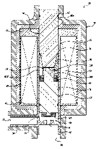
FIGURE 1 is a cross sectional view of one exemplary embodiment of a solenoid
valve formed in accordance with aspects of the present disclosure, wherein the
armature
is in an intermediate position;
FIGURE 2 a cross sectional view of the solenoid valve of FIGURE 1, wherein the
armature is in a valve open position;
FIGURE 3 is a cross sectional view of the solenoid valve of FIGURE 1, wherein
the armature is in a valve closed position;
FIGURE 4 is a perspective view of one embodiment of an upper pole section
formed in accordance with aspects of the present disclosure;
FIGURE 5A is a perspective view of one embodiment of a lower pole section
formed in accordance with aspects of the present disclosure;
FIGURE 5B is a perspective, cross sectional view of the lower pole section of
FIGURE 4A;
FIGURE 6 is a partial cross sectional view of one embodiment of the pole piece
formed in accordance with aspects of the present disclosure, the pole piece
comprising
the upper pole section of FIGURE 4 and the lower pole section of FIGURE 5A;
and
FIGURE 7A and 7B are perspective views of one embodiment of an armature
formed in accordance with aspects of the present disclosure.
DETAILED DESCRIPTION
The detailed description set forth below in connection with the appended
drawings where like numerals reference like elements is intended as a
description of
various embodiments of the disclosed subject matter and is not intended to
represent the
only embodiments. Each embodiment described in this disclosure is provided
merely as
an example or illustration and should not be construed as preferred or
advantageous over
other embodiments. The illustrative examples provided herein are not intended
to be
exhaustive or to limit the claimed subject matter to the precise forms
disclosed.
Similarly, any steps described herein may be interchangeable with other steps,
or
combinations of steps, in order to achieve the same or substantially similar
result.
-3-
CA 02903461 2015-09-01
WO 2014/158993 PCT/US2014/021375
The following description sets forth one or more examples of valves, and more
particularly, of linear actuated valves for controlling the flow of fluid
between a first
passageway and a second passageway. In several embodiments described herein, a
solenoid actuated valve is provided that selectively permits and prohibits
fluid flow
communication between the first passageway and the second passageway. In some
embodiments, a solenoid actuated valve includes a mechanical latch that
provides a de-
energized yet valve open position.
In the following description, numerous specific details are set forth in order
to
provide a thorough understanding of exemplary embodiments of the present
disclosure.
It will be apparent to one skilled in the art, however, that many embodiments
of the
present disclosure may be practiced without some or all of the specific
details. In some
instances, well-known process steps have not been described in detail in order
not to
unnecessarily obscure various aspects of the present disclosure. It will be
appreciated
that embodiments of the present disclosure may employ any combination of
features
described herein.
Referring now to FIGURES 1-3, there is shown an example of a linear actuated
valve, generally designated 20, formed in accordance with aspects of the
present
disclosure. As best shown in FIGURE 1, the valve 20 includes a selectively
movable
armature 24, sometimes referred to as a plunger, which opens and closes the
valve 20,
thereby selectively connecting and disconnecting in fluid communication a
first
passageway 26 with a second passageway 28. The first passageway 26 may be
adapted to
be connected to a supply of pressurized fluid and the second passageway 28 may
be
adapted to be connected to a device for delivery of such fluid, and vice
versa. As will be
described in more detail below, the valve 20 further includes a latching
mechanism 30
that enables the valve 20 to alternate between a mechanically locked open
position and a
mechanically locked closed position via selective actuation of a linear
actuator, such as
the energization of a solenoid.
Referring again to FIGURES 1-7B, the components of the valve 20 will now be
described in more detail. As best shown in the cross sectional view of FIGURE
1, the
valve 20 includes a bobbin 32, which is disposed within a housing 34. The
bobbin 32
includes a tubular portion 36 that defines an elongated internal cavity 38. In
the
embodiment shown, a solenoid coil 40 is wound around the tubular portion 36 of
the
bobbin 32 between first and second spaced flanges 42 and 44 integrally formed
or
-4-
CA 02903461 2015-09-01
WO 2014/158993 PCT/US2014/021375
otherwise secured to the tubular portion 36. The tubular portion 36 of the
bobbin 32
extends longitudinally beyond the first flange 42 to define an integrally
formed inlet
section 48 and outlet section 50. In the embodiment shown, the inlet section
48 includes
the first passageway 26 and the outlet section 50 includes the second
passageway 28. An
aperture 54 in the outlet section 50 of the bobbin 32 provides a fluid
connection between
the second passageway 28 and the elongated internal cavity 38 of the tubular
portion 36
of the bobbin 32.
A generally cylindrical, pole piece 60 is disposed generally in the tubular
portion 36 of the bobbin 32 and, cooperatively with one or more 0-rings 62,
substantially
closes one end of the elongate inner cavity 38. An annularly elevated valve
seat 66 is
integrally formed or otherwise positioned at the opposite end of the tubular
portion 36,
thereby closing the second end of the elongated inner cavity 38. The valve
seat 66
defines a central aperture 70 that provides a fluid connection between the
first
passageway 26 and the elongated internal cavity 38 of the tubular portion 36
of the
bobbin 32.
Still referring to FIGURE 1, the armature 24 is slidably disposed in the
elongated
inner cavity 38 of the tubular portion 36 between the pole piece 60 and the
valve seat 66.
In the embodiment shown, the armature 24 includes a generally cylindrical body
section 76. At the end of the armature 24 nearest the valve seat 66, a seal
80, such as a
layer of polymeric, elastomeric, or rubberized material, is provided. The seal
80 is
positioned so as to overlie the central aperture 70 of the valve seat 66 when
the
armature 24 is urged against the valve seat 66 in the valve closed position
(See
FIGURE 3), thereby prohibiting fluid flow between the first passageway 26 and
the inner
cavity 38. At the end of the armature 24 opposite the seal 80, the armature 24
includes a
boss 84 extending outwardly toward the pole piece 60. The boss 84 is of a
smaller
diameter than the body section 76 and coaxial with the body section 76. As
assembled, a
spring 88, such as a coil spring, is positioned between the armature 24 and a
pole
piece 60. In the embodiment shown, the spring 88 is positioned around the boss
84 of the
armature 24 in-between a shoulder surface of the armature 24 and an end
surface of
pole piece 60. The spring 88 normally biases the armature 24 away from the
pole
piece 60 and toward a valve seat 66.
The pole piece 60 and the armature 24 are made primarily of a ferrous
material,
such that when the solenoid coil 40 is energized, the generated magnetic field
will cause
-5-
CA 02903461 2015-09-01
WO 2014/158993 PCT/US2014/021375
the pole piece 60 and the armature 24 to be magnetically attracted, thereby
forcibly
moving the armature 24 toward the pole piece 60. The armature 24 is forcibly
moved
against the biasing force of the spring 88, and as a result, disengages the
seal 80 from the
valve seat 66 to open the valve 20. When the solenoid coil 40 is de-energized,
the
spring 88 biases the armature 24 toward the valve seat 66 and the closed
position. As
such, the solenoid is of the pull type.
In accordance with aspects of the present disclosure, the valve 20 further
includes
a mechanical latching mechanism, generally designated 30, that maintains the
armature 24 in alternatingly raised and lower positions (open and closed
positions) during
a de-energized condition of the solenoid coil 40. As a result, the armature
moves within
the chamber 38 between three positions, which are: 1) valve closed, solenoid
de-
energized (hereinafter "the valve closed position") as shown in FIGURE 3; 2)
valve open,
solenoid energized (hereinafter "the intermediate position") shown in FIGURE
1; and 3)
valve open, solenoid de-energized (hereinafter "the valve open position")
shown in
FIGURE 2. In use, as will be described in more detail below, a single
energized pulse to
the solenoid coil 40 transitions the armature 24 between the valve open
position and the
valve closed position. As such, at least two energized pulses can operate the
valve
through a complete cycle (e.g., valve closed to valve open and then back to
valve closed).
Turning now to the examples illustrated in FIGURES 4-7B, one embodiment of
the latching mechanism may be formed from cooperating features of the pole
piece 60
and the armature 24. In the embodiment shown in FIGURES 4-6, the pole piece 60
is
comprised of cooperating upper and lower pole piece sections 60A and 60B,
although a
singular pole piece may be practiced with embodiments of the present
disclosure. In
either case, the end portion of the pole piece 60 facing the valve seat 66
(FIGURE 1)
defines a cylindrical socket 92 for receiving the boss 84 of the armature 24
as the
armature 24 is forcibly moved away from the valve seat 66 against the spring
88 by
energizing the solenoid coil 40.
The latching mechanism 30 includes a plurality of first armature engaging
interfaces 100. In some embodiments, the interfaces 100 are formed on the
inner side
walls 94 of the socket 92. In the embodiment shown, the plurality (shown as
four) of first
armature engaging interfaces 100 are evenly spaced apart around the inner
perimeter of
inner side walls 94 (shown in FIGURE 5B and 6 as integrally formed on the pole
piece
section 60B). The plurality of first armature engaging interfaces 100 extend
inwardly
-6-
CA 02903461 2015-09-01
WO 2014/158993 PCT/US2014/021375
into the socket 92 and define grooves or parallely extending slots 106 between
one
another. As will be described in more detail below, the slots 106 are sized
and configured
to slidably receive sections of the armature 24 for providing guided,
translational
movement of the armature between the valve closed position and the
intermediate
position. At the same time, the slots also provide minimal rotation of the
armature as it
translates within slots 106.
Each first armature engagement interface 100 further includes a cam surface
110
facing away from the valve seat 66 in the longitudinal direction of chamber 38
(See
FIGURE 1). In that regard, each cam surface 110 is configured to cooperate
with a
portion of the armature 24 in order to rotate and lock the armature 24 as
described below.
In one embodiment, the cam surfaces 110 define a first or guide portion 110A
and a
second or notch portion 110B, as best shown in FIGURES 5B and 6. As will be
described in more detail below, when the armature 24 interfaces with the cam
surfaces 110, the cam surfaces 110 cause the armature 24 to rotate along the
guide
portion 110A and contact the notch portion 110B, thereby retaining or
"locking" the
armature 24 into the de-energized, open position.
The latching mechanism 30 also includes a plurality of second armature
engaging
interfaces 120. In the embodiment shown, the plurality (shown as eight) of
second
armature engaging interfaces 120 are evenly spaced apart around the perimeter
of an
inner end surface 116 of the pole piece 60 (shown in FIGURE 4 with pole piece
60A).
The plurality of second armature engaging interfaces 120 extend inwardly into
the
socket 92 generally orthogonal to the first armature engaging interfaces 100,
as best
shown in FIGURE 6. Each second armature engaging interface 120 includes a cam
surface 124 facing toward valve seat 66. When assembled, alternating (i.e.,
every other)
second armature engaging interface 120 generally aligns with the slots 106.
The plurality
of second armature engaging interfaces 120 function to rotate the armature 24
a selected
amount (e.g. 45 degrees) when the armature 24 contacts the pole piece 60. In
operation,
the armature 24 contacts the plurality of second armature engaging interfaces
120 each
time the solenoid coil 40 is energized. The linear position of the armature 24
shown in
FIGURE 1 in which the armature 24 contacts the plurality of the second
armature
engagement interfaces 120 when the coil 40 is energized is referred to herein
as the
intermediate position.
-7-
CA 02903461 2015-09-01
WO 2014/158993 PCT/US2014/021375
The latching mechanism 30 further includes a plurality of teeth 140 disposed
at
the upper end of the boss 84 of the armature 24, as best shown in FIGURE. 4.
In the
embodiment shown, the plurality (shown as four) of teeth 140 are evenly spaced
apart
around the outer perimeter of the boss 84. As shown in the embodiment of
FIGURES 7A-7B, the teeth 140 radially extend outwardly and upwardly from the
boss 84. Each tooth 140 is sized and configured to be slideably received
within
respective slots 106 of the pole piece 60. In the embodiment shown in FIGURE
7A, the
teeth 140 define first cam surfaces 142 on its upper surface (i.e., surface
facing away
from valve seat 66) for interfacing with the second armature engagement
interfaces 120.
The first cam surfaces 142 and the cam surfaces 124 are cooperatively
configured such
that when the armature teeth 140 contact the cam surfaces 124 of the second
armature
engagement interfaces 120, the upward biasing force provided by the energized
coil 40
rotates the armature 24 relative to the pole piece 60 about a common
longitudinal axis so
that the armature teeth 140 are no longer aligned with the slots 106.
The teeth 140 further define second cam surfaces 148 on its lower surface
(i.e.,
surface facing toward the valve seat 66) for interfacing with the cam surfaces
110 of the
first armature engagement interfaces 100, as best shown in FIGURE 7B. The
second cam
surfaces148 are angled and somewhat parallel to the first portion 110A of the
cam
surfaces 110. As a result, when the armature teeth 140 contact the first
armature
engagement interface 100, the downward biasing force provided by the spring 88
(in a
solenoid de-energized state) rotates the armature 24 relative to the pole
piece 60 about a
common longitudinal axis until the armature 24 is locked from further rotation
(and
translation toward the valve seat 66) by the notch portion 110B of the cam
surfaces 110.
On the other hand, when the valve 20 is in the valve closed position, the
teeth 140 of the
armature 24 are slidably engaged within slots 106. When so positioned, the
slots 106
prevent rotation of the armature 24, while the spring 88 biases the armature
24 downward
to keep the seal engaged with the valve seat 66.
One example operation of the valve 20 will now be described with reference
with
FIGURES 1-7B. As best shown in FIGURE 3, the valve 20 is in the valve closed
position, where 1) the solenoid coil 40 is in a de-energized state; 2) the
spring 88 is
forcibly biasing the armature 24 against the valve seat 66; 3) the seal 80 is
blocking the
aperture 70; and the teeth 140 of the armature 24 are positioned within the
slots 106,
thereby preventing rotation of the armature 24 (See FIGURE 6 and 7A-7B). To
open the
-8-
CA 02903461 2015-09-01
WO 2014/158993 PCT/US2014/021375
valve 20, the solenoid coil 40 is energized, causing the armature 24 to move
away from
the valve seat 66. As the armature 24 moves away from the valve seat 66
against the
biasing force of the spring 88, the seal 80 unblocks the aperture 70, the
teeth 140 slide
within the slots 106 with minimal rotation, and the spring 88 compresses.
During
energization, the armature teeth 140 move through and out of the slots 106 of
the pole
piece 60, and continue to move away from the valve seat 66 to the intermediate
position
shown in FIGURE 1. In the intermediate position, the armature teeth 140
contact the
second armature engagement interfaces 120. Due to the cooperating cam surfaces
144
and 124 of the teeth 140 and second armature engagement interfaces 120,
respectively,
the upward biasing force provided by the energized coil 40 rotates the
armature 24
relative to the pole piece 60 so that the armature teeth 140 are no longer
aligned with the
slots 106 formed in pole piece 60.
When the coil 40 is de-energized, the spring 88 biases the armature 24 toward
the
valve seat 66. Since the teeth 140 are no longer aligned with the slots 106,
the armature
teeth 140 contact the cam surfaces 110 of the first armature engagement
interfaces 100 at
the guide portion 110A. The guide portion 110A of the cam surfaces 110 of the
pole
piece 60 are angled and somewhat parallel to the lower cam surfaces 148 of the
armature
teeth 140 so that after contact is made, the continued downward force applied
by the
spring 88 rotates the armature 24 until the armature teeth 24 are fully
engaged with notch
portion 110B. When so located, the spring 88 biases the armature teeth 140
against the
notch portion 110B to maintain the position of the armature 24 such that the
seal 80 is
located above the valve seat 66 in an unseated position. Thus, the valve 20 is
maintained
in an open, but mechanically locked position when the coil is de-energized,
which is
otherwise known as the valve open position and shown best in FIGURE 2.
To close the valve 20, the solenoid coil 40 is again energized to move the
armature 24 upward against the biasing force of the spring 88. When the upper
cam
surfaces 144 of the armature teeth 140 again contact the second armature
engagement
interfaces 120 of the pole piece 60 in the intermediate position of FIGURE 1,
the
armature 24 rotates until the armature teeth 140 are again aligned with the
slots 106. The
coil 40 is then de-energized, and the biasing force of the spring 88 moves the
armature 24
away from the second armature engagement interfaces 120 so that the armature
teeth 140
are received within and slide along the slots 106 until the armature 24 has
reached the
valve closed position shown best in FIGURE 3. In the valve closed position,
the seal 80
-9-
CA 02903461 2015-10-09
is engaged with the valve seat 66, thereby preventing fluid communication
between the
first passageway and the second passageway 28. The valve 20 is maintained in a
closed
position when the coil is de-energized by the biasing force of the spring 88.
It should be noted that for purposes of this disclosure, terminology such as
"upper," "lower," "vertical," "horizontal," "fore," "aft," "inner," "outer,"
"front," "rear,"
etc., should be construed as descriptive and not limiting the scope of the
claimed subject
matter. Further, the use of "including," "comprising," or "having" and
variations thereof
herein is meant to encompass the items listed thereafter and equivalents
thereof as well as
additional items. Unless limited otherwise, the terms "connected," "coupled,"
and
"mounted" and variations thereof herein are used broadly and encompass direct
and
indirect connections, couplings, and mountings. Similarly, the terms "facing,"
"faces"
and variations thereof herein are used broadly and encompass direct and
indirect facing.
Therefore, the description of "A" component facing "B" component herein may
contain
the situations that "A" component facing "B" component directly or one or more
additional components is between "A" component and "B" component.
The principles, representative embodiments, and modes of operation of the
present disclosure have been described in the foregoing description. However,
aspects of
the present disclosure which are intended to be protected are not to be
construed as
limited to the particular embodiments disclosed. Further, the embodiments
described
herein are to be regarded as illustrative rather than restrictive. It will be
appreciated that
variations and changes may be made by others, and equivalents employed,
without
departing from the present disclosure. Accordingly, it is expressly intended
that all such
variations, changes, and equivalents fall within the scope of the present
disclosure, as
claimed.
-10-