Note : Les descriptions sont présentées dans la langue officielle dans laquelle elles ont été soumises.
CA 02904495 2015-09-08
DESCRIPTION
VEHICULAR BRAKE SYSTEM
Technical Field
[0001]
The present invention relates to a vehicular brake system.
Background Art
[0002]
For example, Patent Literature 1 discloses a braking force control
device that uses both mechanical braking force (friction braking force) and
regenerative braking force, and further improves the stability of a vehicle
during braking by ABS (Antilock Brake System) control.
Related Art Document
Patent Literature
[0003]
Patent Literature 1: JP 2000-062590 A
Disclosure of the Invention
Problems to be Solved by the Invention
[0004]
1
CA 02904495 2015-09-08
By the braking force control device disclosed by Patent Literature 1,
friction braking force is applied to all of four wheels, and regenerative
braking force is applied only to driving wheels (left and right front wheels)
driven by a driving motor as a movement power source. Consequently,
regenerative braking force and friction braking force are applied to the
driving wheels while only friction braking force is applied to the non-driving
wheels (left and right rear wheels). In such a manner, as the braking forces
applied to the driving wheels and the non-driving wheels are caused to be
unbalanced with each other, which sometimes make the behavior of a vehicle
unstable during braking, depending on the state of a road surface.
[0005]
If wheels slip and the behavior of a vehicle becomes unstable during
braking, an ABS device is activated. The ABS device adjusts friction
braking force and controls the attitude of the vehicle. Accordingly, the
regenerative braking force is decreased during operation of the ABS device,
and generation of regenerative braking force is thereby stopped. The ABS
device decreases the friction braking force so as to make a wheel recover
from slip. Further, the ABS device is configured to stabilize the vehicle by
increasing or decreasing the friction braking force. Accordingly, for example,
when a wheel recovers from a slip and the friction braking force is increased,
it is necessary to generate braking force that compensates the regenerative
braking force having been decreased during operation of the ABS device and
the friction braking force having been decreased by operation of the ABS
device. If the braking force is not compensated, the braking force generated
2
CA 02904495 2015-09-08
on the vehicle sometimes become short of a requested braking force
requested by the driver.
[0006]
In this situation, an object of the invention is to provide a vehicular
brake system that uses both friction braking force generated by an electrical
braking unit and regenerative braking force generated by a regenerative
braking unit, and can reduce a shortage in braking force when a slip has
occurred on a wheel and antilock control is activated.
Means for Solving the Problems
[0007]
In order to solve the above-described problem, according to the
invention, a vehicular brake system includes: an electrical braking unit that
supplies operational pressure generated in operational fluid by an electrical
brake actuator to wheel cylinders and thereby applies friction braking force
to wheels; a regenerative braking unit for applying regenerative braking
force generated by an electrical motor to a driving wheel; and an antilock
control unit for activating antilock control that increases and decreases the
friction braking force to stop slip of a wheel, wherein the vehicular brake
system is provided on a vehicle having the wheels including the driving
wheel rotationally driven by then electrical motor, and wherein when the
antilock control unit determines that at least one slip wheel has occurred
and activates the antilock control, the antilock control unit maintains a
state
where the regenerative braking force is applied to the driving wheel.
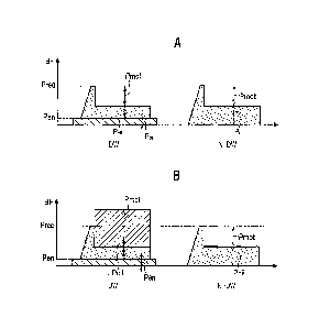
3
CA 02904495 2015-09-08
[0008]
In this aspect of the invention, by a vehicular brake system capable of
applying friction braking force and regenerative braking force to wheels,
when at least one slip wheel has occurred, it is possible to activate antilock
control while maintaining the regenerative braking force applied to a driving
wheel. Thus, when antilock control is activated, both the friction braking
force and the regenerative braking force are applied to the wheel, and
antilock control can be activated such as to generate braking force without a
shortage compared with requested braking force requested by a driver.
[0009]
Further, in another aspect of the invention, the antilock control unit
increases and decreases the operational pressure by the electrical brake
actuator while the antilock control is activated.
[0010]
In this aspect of the invention, operational pressure can be increased
and decreased by an electrical brake actuator while the antilock control is
activated. Accordingly, friction braking force applied to a wheel can be
adjusted by the electrical brake actuator.
[0011]
The antilock control unit of the vehicular brake system in still
another aspect of the invention maintains the regenerative braking force
constant while the antilock control is activated.
[0012]
4
CA 02904495 2015-09-08
In this aspect of the invention, when antilock control is activated, the
regenerative braking force applied to a driving wheel is maintained
constant. Accordingly, when antilock control is activated, regenerative
braking force can also be used. In addition, when the antilock control is
activated, shortage in the braking force can be reduced.
[0013]
While the antilock control is activated, the antilock control unit of the
vehicular brake system in yet another aspect of the invention subtracts a
braking force corresponding to the friction braking force applied to a
non-driving wheel out of the wheels, the non-driving wheel being not the
driving wheel, from the regenerative braking force applied to the driving
wheel.
[0014]
In this aspect of the invention, it is possible to avoid generation of
excessive braking force while the antilock control is activated.
[0015]
When the antilock control unit of the vehicular brake system in
another aspect of the invention has determined that slip ratio of the slip
wheel has become smaller than or equal to a predetermined value, the
antilock control unit opens an opening-closing unit for a supply passage
supplying the operational pressure to the wheel cylinder provided at the slip
wheel, to supply the operational pressure from the supply passage to the
wheel cylinder, thereby increases the friction braking force applied to the
slip
5
CA 02904495 2015-09-08
wheel, and decreases the regenerative braking force that is applied to the
driving wheel by the regenerative braking unit.
[0016]
In this aspect of the invention, it is possible to increase the friction
braking force when the slip of the slip wheel has stopped, and further
decrease the regenerative braking force applied to the driving wheel.
Accordingly, it is possible to prevent a wheel from being applied an excessive
braking force.
[0017]
While the antilock control is activated, the antilock control unit of the
vehicular brake system in still another aspect of the invention opens an
opening-closing unit for a supply passage supplying the operational pressure
to the wheel cylinder provided at the slip wheel, to supply the operational
pressure from the supply passage to the wheel cylinder, thereby increases
the friction braking force applied to the slip wheel, and decreases the
regenerative braking force that is applied to the driving wheel by the
regenerative braking unit.
[0018]
In this aspect of the invention, it is possible to decrease the
regenerative braking force while increasing the friction braking force when
the antilock control is activated by the antilock control unit. Accordingly,
it
is possible to prevent a wheel from being applied an excessive braking force
while the antilock control is activated.
6
CA 02904495 2015-09-08
Advantages of the Invention
[0019]
According to the invention, it is possible to provide a vehicular brake
system that uses both friction braking force generated by an electrical
braking unit and regenerative braking force generated by a regenerative
braking unit, and can reduce a shortage in braking force when a slip occurs
on a wheel and antilock control is activated.
Brief Description of the Drawings
[0020]
Fig. 1 shows the schematic configuration of a vehicular brake system;
Fig. 2A shows friction braking forces applied respectively to driving
wheels and non-driving wheels, Fig. 2B shows a state where a regenerative
driving force is applied to the driving wheels;
Fig. 3A shows a graph representing variation in the vehicle speed
during braking, Fig. 3B shows a graph representing variation in friction
braking force generated on the vehicle, Fig. 3C shows a graph representing
variation in regenerative braking force generated on the vehicle; and
Fig. 4 shows examples of patterns of decreasing regenerative braking
force.
Embodiment for Carrying Out the Invention
[0021]
7
CA 02904495 2015-09-08
In the following, an embodiment according to the present invention
will be described in detail, referring to the drawings, as appropriate.
Fig. 1 shows the schematic configuration of a vehicular brake system
according to an embodiment of the invention. Fig. 2A shows respective
friction braking forces applied to driving wheels and non-driving wheels.
Fig. 2B shows a state where a regenerative driving force is applied to the
driving wheels.
Incidentally, in Figs. 2A and 2B, the figure (DW) on the left side
shows a driving wheel and the figure (N-DW) on the right side shows a
non-driving wheel. The vertical axis represents braking force (BF).
[0022]
A vehicular brake system 10 shown in Fig. 1 is provided with both a
brake system of a by-wire type for normal use, which operates a brake by
transmitting an electrical signal, and a conventional hydraulic brake system
for failsafe use, which operates a brake by transferring a hydraulic pressure
(hydraulic brake pressure).
[0023]
For this arrangement, a vehicular brake system 10 shown in Fig. 1
basically includes, as separated units, a hydraulic pressure generating
device (input device 14) for making a brake fluid, the brake fluid being an
operating fluid, generate a hydraulic pressure corresponding to an input of
operation of a brake operation section such as a brake pedal 12 by a driver, a
pedal stroke sensor St (Sens.) for measuring an operation amount (stroke)
when the brake pedal 12 is subjected to pedaling operation, an electrical
8
CA 02904495 2015-09-08
brake actuator (motor cylinder device 16) for generating an operating
pressure (hydraulic brake pressure) of an operating fluid (brake fluid)
supplied to the wheel cylinders 32FR, 32RL, 32RR, and 32FL of respective
wheels (front right wheel WFR, rear left wheel WRL, rear right wheel WRR,
and front left wheel WFL), and a vehicle behavior stabilizing device 18
(hereinafter, referred to as a VSA (vehicle stability assist) device 18, VSA;
registered trademark) for assisting stabilization of the vehicle.
[0024]
These devices, namely, the input device 14, the motor cylinder device
16, and the VSA device 18 are connected by tube passages (hydraulic
passages) formed by a tube member, for example, a hose or a tube. Further,
as a by-wire brake system, the input device 14 and the motor cylinder device
16 are electrically connected by a harness (not shown).
[0025]
First, hydraulic passages will be described. With a connection point
Al in Fig. 1 (a little lower than the center) as a reference, a connection
port
20a of the hydraulic-pressure generation device 14 and the connection point
Al are connected by a first piping tube 22a. Further, an output port 24a of
the motor cylinder device 16 and the connection point Al are connected by a
second piping tube 22b. Still further, an inlet port 26a of the VSA device 18
and the connection point Al are connected by a third piping tube 22c.
[0026]
With another connection point A2 in Fig. 1 as a reference, another
connection port 20b of the input device 14 and the connection point A2 are
9
CA 02904495 2015-09-08
connected by a fourth piping tube 22d; another output port 24h of the motor
cylinder device 16 and the connection point A2 are connected by a fifth piping
tube 22e; and further, another inlet port 26b of the VSA device 18 and the
connection point A2 are connected by a sixth piping tube 22f.
[0027]
The VSA device 18 is provided with a plurality of outlet ports 28a to
28d. The first outlet port 28a is connected, by a seventh piping tube 22g,
with the wheel cylinder 32FR of a disk brake mechanism 30a provided at the
front right wheel WFR. The second outlet port 28b is connected, by an
eighth piping tube 22h, with the wheel cylinder 32RL of a disk brake
mechanism 30b provided at the rear left wheel WRL. The third outlet port
28c is connected, by a ninth piping tube 22i, with the wheel cylinder 32RR of
a disk brake mechanism 30e provided at the rear right wheel WRR. The
fourth outlet port 28d is connected, by a tenth piping tube 22j, with a wheel
cylinder 32FL of a disk brake mechanism 30d provided at the front left wheel
WFL.
[0028]
Herein, brake fluid is supplied, through the piping tubes 22g-22j
connected with the respective outlet ports 28a-28d, to the respective wheel
cylinders 32FR, 32RL, 32RR, and 32FL of the disk brake mechanisms
30a-30d. Rise in the hydraulic brake pressure in the wheel cylinders 32FR,
32RL, 32RR, or 32FL operates the corresponding wheel cylinders 32FR,
32RL, 32RR, or 32FL, thus the friction force with the corresponding wheel
(front right wheel WFR, rear left wheel WRL, rear right wheel WRR, or front
CA 02904495 2015-09-08
left wheel WFL) increases, and braking force is thereby applied. A braking
force generated in such a manner by a rise in the hydraulic brake pressure in
the each wheel cylinder 32FR, 32RL. 32RR, or 32FL will be hereinafter
referred to as a friction braking force Poil.
[0029]
Further, each of the front right wheel WFR, the rear left wheel WRL,
the rear right wheel WRR, and the front left wheel WFL is provided with a
wheel speed sensor 35a, 35b, 35c, or 35d (S) for detecting the wheel speed;
the each of the wheel speed sensor 35a, 35b, 35c, and 35d measures the
corresponding wheel speed; and each measurement signal generated by the
measuring is input to a control unit 150 (Cont.).
[0030]
Incidentally, the vehicular brake system 10 in the present
embodiment can be mounted on a vehicle provided with an electrical motor
200 as a movement power source, such as a hybrid vehicle with an engine
(internal combustion engine) and the electrical motor 200 (Mot.) as
movement power sources, or an electrical vehicle with only the electrical
motor 200 as a movement power source.
The electrical motor 200 is arranged on the vehicle to drive, for
example, two front wheels (front right wheel WFR, front left wheel WFL).
In this case, the two front wheels serve as driving wheels, and the two rear
wheels (rear left wheel WRL, rear right wheel WRR) serve as non-driving
wheels.
[0031]
11
CA 02904495 2015-09-08
A regeneration control device 201 (RGcont.) is connected to the
electrical motor 200. The regeneration control device 201 has a function to
charge a battery 202 (Batt.) with an electrical power (regenerative power)
generated by the electrical motor 200 with a torque input from driving
wheels, and is controlled by instructions input from the control unit 150.
For example, upon input of an instruction from the control unit 150 to make
the electrical motor 200 generate a regenerative power and thereby generate
a braking force (regenerative braking force Pmot), the regeneration control
device 201 switches the electrical motor 200 to 'a power generator' and
functions to charge the battery 202 (Batt.) with the regenerative power
generated by the electrical motor 200.
Further, the regeneration control device 201 is configured to be able
to adjust the strength of the regenerative braking force Pmot generated by
the electrical motor 200, for example, by varying a field current to be
supplied to, for example, the electrical motor 200 and thus adjusting the
generated power amount of the regenerative power by the electrical motor
200.
Accordingly, in the present embodiment, a regeneration brake unit is
configured, including the control unit 150, the electrical motor 200, and the
regeneration control device 201. Incidentally, a known technology can be
used as a technology for making the regeneration control device 201 control
the electrical motor 200 to generate the regenerative braking force Pmot.
[0032]
12
CA 02904495 2015-09-08
The input device 14 includes a tandem type master cylinder 34
capable of generating a hydraulic pressure of the brake fluid by operation of
the brake pedal 12 by the driver, and a reservoir (first reservoir 36)
attached
to the master cylinder 34. Inside a cylinder tube 38 of the master cylinder
34, two pistons (secondary piston 40a and a primary piston 40b) are slidably
arranged, wherein the two pistons 40a and 40b are separated from each
other by a certain distance along the axial direction of the cylinder tube 38.
The secondary piston 40a is disposed adjacent to the brake pedal 12 and is
connected with the brake pedal 12 through a push rod 42. The primary
piston 40b is disposed at a longer distance than the piston 40a is from the
brake pedal 12.
[00331
Further, to the inner wall of the cylinder tube 38, there are attached
cup seals 44Pa, 44Pb in a pair of ring shapes in slidable contact with the
outer circumference of the primary piston 40b, and cup seals 44Sa, 44Sb in a
pair of ring shapes in slidable contact with the outer circumference of the
secondary piston 40a. Further, a spring member 50a is provided between
the secondary piston 40a and the primary piston 40b, and another spring
member 50b is provided between the primary piston 40b and the side end
portion 38a, on the closed end side, of the cylinder tube 38.
[0034]
Still further, a guide rod 48b is arranged, extending along the sliding
direction of the primary piston 40b from the side end portion 38a of the
13
CA 02904495 2015-09-08
cylinder tube 38. The primary piston 40b is guided by the guide rod 48b,
and thus slide.
Yet further, a guide rod 48a is arranged, extending along the sliding
direction of the secondary piston 40a from the end portion, on the secondary
piston 40a side, of the primary piston 40b. The secondary piston 40a is
guided by the guide rod 48a, and thus slides.
The secondary piston 40a and the primary piston 40b are connected
by the guide rod 48a and serially disposed. Details of the guide rods 48a,
48b will be described later.
[0035]
Further, the cylinder tube 38 of the master cylinder 34 is provided
with two supply ports (second supply port 46a, first supply port 46b), two
relief ports (second relief port 52a, first relief port 52b), and two output
ports
54a, 54b. Herein, the second supply port 46a, the first supply port 46b, the
second relief port 52a, and the first relief port 52b are arranged such as to
join with each other and communicate with a reservoir chamber (not shown)
in the first reservoir 36.
Still further, the pair of the cup seal 44So, 44Sb in slidable contact
with the outer circumference of the secondary piston 40a are disposed along
the sliding direction of the secondary piston 40a with the second relief port
52a in between. Further, the pair of cup seals 44Pa, 44Pb in slidable
contact with the outer circumference of the primary piston 40b are disposed
in the sliding direction of the primary piston 40b with the first relief port
52b
in between.
14
CA 02904495 2015-09-08
[0036]
Further, inside the cylinder tube 38 of the master cylinder 34, there
are provided a second pressure chamber 56a and a first pressure chamber
56b that generate a hydraulic pressure corresponding to a pedal effort on the
brake pedal 12 by the driver. The second pressure chamber 56a is arranged
such as to communicate with the connection port 20a through a second
hydraulic pressure passage 58a, and the first pressure chamber 56b is
arranged such as to communicate with the other connection port 20b through
the first hydraulic pressure passage 58b.
The space between the first pressure chamber 56b and the second
pressure chamber 56a is tightly fluid-sealed by the pair of cup seals 44Pa,
44Pb. Further, the brake pedal 12 side of the second pressure chamber 56a
is tightly fluid-sealed by the pair of cup seals 44Sa, 44Sb.
[0037]
The first pressure chamber 56b is arranged such as to generate a
hydraulic pressure corresponding to the displacement of the primary piston
40b, and the second pressure chamber 56a is arranged such as to generate a
hydraulic pressure corresponding to the displacement of the secondary
piston 40a.
The secondary piston 40a is connected with the brake pedal 12
through a pushrod 42 to be displaced inside the cylinder tube 38,
accompanying the operation of the brake pedal 12. Further, the primary
piston 40b is displaced by a hydraulic pressure generated in the second
pressure chamber 56a by the displacement of the secondary piston 40a.
CA 02904495 2015-09-08
That is, the primary piston 40b is displaced in association with the secondary
piston 40a.
[0038]
A pressure sensor Pm is arranged between the master cylinder 34
and the connection port 20a and on the upstream side of the second
hydraulic pressure passage 58a, a second shut-off valve 60a is provided on
the downstream side of the second hydraulic pressure passage 58a, wherein
the second shut-off valve 60a is a solenoid valve of a normal open type.
The pressure sensor Pm measures the hydraulic pressure in the second
hydraulic pressure passage 58a and on the upstream side, in other words,
the master cylinder 34 side with respect to the second shut-off valve 60a.
[0039]
A first shut-off valve 60b is provided between the master cylinder 34
and the other connection port 20b and on the upstream side of the first
hydraulic pressure passage 58b, the first shut-off valve 60b being a solenoid
valve of a normal open type. A pressure sensor Pp is provided on the
downstream side of the first hydraulic pressure passage 58b. The pressure
sensor Pp measures the hydraulic pressure in the first hydraulic pressure
passage 58b on the downstream side, in other words, on the side of the wheel
cylinders 32FR, 32RL, 32RR, and 32FL with respect to the first shut-off
valve 60b.
[0040]
Normal open regarding the second shut-off valve 60a and the first
shut-off valve 60b refers to a valve arranged such that the normal position
16
CA 02904495 2015-09-08
(the position of the valve body when current is not applied) is in a state
(normally open) at an open position. Incidentally, Fig. 1 shows a
valve-closed state where current is applied to the solenoids of the second
shut-off valve 60a and the first shut-off valve 60b, and the valve bodies (not
shown) of are operated.
[00411
The first hydraulic pressure passage 58b between the master
cylinder 34 and the first shut-off valve 60b is provided with a branched
hydraulic pressure passage 58c branched from the first hydraulic pressure
passage 58b. A third shut-off valve 62, which is a solenoid valve of a normal
close type, and a stroke simulator 64 are serially connected to the branched
hydraulic pressure passage 58c. Normal close regarding the third shut-off
valve 62 refers to a valve arranged such that the normal position (the
position of the valve body when current is not applied) is in a state
(normally
closed) at a close position. Incidentally, Fig. 1 shows a valve-open state
where current is applied to the solenoid of the third shut-off valve 62, and
the valve body (not shown) is operated.
[00421
The stroke simulator 64 is a device that applies a stroke and a
reaction force on the pedaling operation of the brake pedal 12 during by-wire
control, and makes the driver feel as if a braking force were generated by a
pedal effort. The stroke simulator 64 is disposed on the first hydraulic
pressure passage 58b and on the master cylinder 34 side with respect to the
first shut-off valve 60b. The stroke simulator 64 is provided with a
17
CA 02904495 2015-09-08
hydraulic pressure chamber 65 communicating with the branched hydraulic
pressure passage 58c so that brake fluid flowed out from the first pressure
chamber 56b of the master cylinder 34 can be absorbed through the
above-described hydraulic pressure chamber 65.
[0043]
Further, the stroke simulator 64 is provided with a first return
spring 66a with a larger spring constant and a second return spring 66b with
a smaller spring constant, which are disposed serial with each other, and a
simulator piston 68 urged by the first and second return springs 66a, 66b.
Herein, the stroke simulator 64 is arranged such that the increase gradient
of the pedal reaction force is set small during the early stage of pedaling
the
brake pedal 12, and the pedal reaction force is set large during the later
stage of pedaling so that the pedal feeling of the brake pedal 12 becomes
equal to the pedal feeling at the time of pedaling operation of an existing
master cylinder 34.
That is, the stroke simulator 64 is configured to generate a reaction
force corresponding to the hydraulic pressure of the brake fluid flowing out
from the first pressure chamber 56b, and applies this reaction force to the
brake pedal 12 through the master cylinder 34. The details of the master
cylinder 34 will be described later.
[0044]
The configuration of the hydraulic passages is roughly categorized
into a second hydraulic system 70a that connects the second pressure
chamber 56a of the master cylinder 34 and the plurality of wheel cylinders
18
CA 02904495 2015-09-08
32FR and 32RL , and a first hydraulic system 70b that connects the first
pressure chamber 56b of the master cylinder 34 and the plurality of wheel
cylinders 32RR and 32FL.
[0045]
The second hydraulic pressure system 70a is configured by the
second hydraulic pressure passage 58a that connects the output port 54a of
the master cylinder 34 (cylinder tube 38) of the input device 14 and the
connection port 20a; piping tubes 22a, 22b that connect the connection port
20a of the input device 14 and the outlet port 24a of the motor cylinder
device
16; piping tubes 22b, 22c that connect the output port 24a of the motor
cylinder device 16 and the inlet port 26a of the VSA device 18; and piping
tunes 22g, 22h that connect the outlet ports 28a, 28b of the VSA device 18
and the respective wheel cylinders 32FR, 32RL.
[0046]
The first hydraulic system 70b includes the first hydraulic pressure
passage 58b connecting the output ports 54b of the master cylinder 34
(cylinder tube 38) of the input device 14 and the other connection port 20b;
the piping tubes 22d, 22e connecting the other connection port 20b of the
input device 14 and the output port 24b of the motor cylinder device 16; the
piping tubes 22e, 22f connecting the output port 24b of the motor cylinder
device 16 and the inlet port 26b of the VSA device 18; and the piping tubes
22i, 22j connecting the outlet ports 28c, 28d of the VSA device 18 and the
respective wheel cylinders 32RR, 32FL.
[0047]
19
CA 02904495 2015-09-08
The motor cylinder device 16 includes an electrical machine
(electrical motor 72), an actuator mechanism 74, and a cylinder mechanism
76 urged by the actuator mechanism 74.
[0048]
The actuator mechanism 74 is arranged on the output shaft 72b side
of the electrical motor 72 and includes a gear mechanism (deceleration
mechanism) 78, the plurality of gears of the gear mechanism 78 engaging
with each other to transmit the rotational driving force of the electrical
motor 72; and a ball screw assembly 80 that includes a ball screw shaft 80a
and balls 80b, the ball screw shaft 80a moves forward and backward along
the axial direction by that the above-described rotational driving force is
transmitted through the gear mechanism78.
In the present embodiment, the ball screw assembly 80 is housed in a
mechanism housing section 173a of an actuator housing 172, together with
the gear mechanism 78.
[0049]
The cylinder mechanism 76 includes a cylinder main body 82
substantially in a cylindrical shape, and a second reservoir 84 attached to
the cylinder main body 82. The second reservoir 84 is connected with the
first reservoir 36 attached to the master cylinder 34 of the input device 14
by
a piping tube 86, and the brake fluid stored in the first reservoir 36 is
supplied into the second reservoir 84 through the piping tube 86.
Incidentally, the piping tube 86 may be provided with a tank for storing the
brake fluid.
CA 02904495 2015-09-08
The open end portion (open end) of the cylinder main body 82
substantially in a cylindrical shape is fitted to an actuator housing 172
configured by a housing main body 172F and a housing cover 172R so that
the cylinder main body 82 and the actuator housing 172 are connected, and
the motor cylinder device 16 is thus configured.
[0050]
In the cylinder main body 82, a second slave piston 88a and a first
slave piston 88b are slidably arranged such as to be separate from each other
at a certain distance along the axial direction of the cylinder main body 82.
The second slave piston 88a is disposed adjacent to the ball screw assembly
80 side, and contacts one end portion of the ball screw shaft 80a to be
displaced integrally with the ball screw shaft 80a in the direction
represented by arrow X1 or X2. The first slave piston 88b is disposed
farther from the ball screw assembly 80 side than the second slave piston
88a is.
[0051]
The electrical motor 72 in the present embodiment is covered by a
motor casing 72a formed separately from the cylinder main body 82. The
output shaft 72b of the electrical motor 72 is disposed substantially in
parallel to the sliding direction (axial direction) of the second slave piston
88a and the first slave piston 88b.
The rotational driving of the output shaft 72b is transmitted to the
ball screw assembly 80 through the gear mechanism 78.
[0052]
21
CA 02904495 2015-09-08
The gear mechanism 78 is configured, for example, by three gears,
namely, a first gear 78a attached to the output shaft 72b of the electrical
motor 72, a third gear 78c that rotates the ball 80b around the axial
direction
of the ball screw shaft 80a, the ball 80b moving the ball screw shaft 80a
forward and backward along the axial direction, and a second gear 78b that
transmits the rotation of the first gear 78a to the third gear 78c. Herein,
the third gear 78c rotates around the axial line of the ball screw shaft 80a.
[0053]
With the above-described structure, the actuator mechanism 74 in
the present embodiment converts the rotational driving force of the output
shaft 72b of the electrical motor 72 into the forward-backward driving force
(linear driving force) of the ball screw shaft 80a.
[0054]
A pair of slave cup seals 90a, 90b is attached, through an annular
stepped portion, to the outer circumferential surface of the first slave
piston
88b. A first back chamber 94b, which communicates with a later-described
reservoir port 92b, is formed between the pair of slave cup seals 90a, 90b.
Incidentally, a second return spring 96a is arranged between the
second and first slave pistons 88a, 88b. A first return spring 96b is
arranged between the first slave piston 88b and the side end portion of the
cylinder main body 82.
[0055]
Further, an annular guide piston 90c, which tightly fluid-seals the
space between the outer circumferential surface of the second slave piston
22
CA 02904495 2015-09-08
88a and the mechanism housing section 173a and movably guides the second
slave piston 88a along the axial direction of the second slave piston 88a, is
provided posterior to the second slave piston 88a such as to close the
cylinder
main body 82 as a seal member. It is preferable that a slave cup seal (not
shown) is attached to the inner circumferential surface of a guide piston 90c
which the second slave piston 88a penetrates, and the space between the
second slave piston 88a and the guide piston 90c is tightly fluid-sealed.
Further, a slave cup seal 90b is attached to the front outer circumferential
surface of the second slave piston 88a through an annular stepped portion.
By this configuration, brake fluid charged into the cylinder main
body 82 is trapped in the cylinder main body 82 by the guide piston 90c and
is thus prevented from flowing out to the side of the actuator housing 172.
Incidentally, a second back chamber 94a communicating with a
later-described reservoir port 92a is formed between the guide piston 90c and
the slave cup seal 90b.
[0056]
The cylinder main body 82 of the cylinder mechanism 76 is provided
with two reservoir ports 92a, 92b and two output ports 24a, 24b. Herein,
the reservoir ports 92a (92b) are arranged such as to communicate with a
reservoir chamber (not shown) in the second reservoir 84.
[0057]
Further, in the cylinder main body 82, there are provided a second
hydraulic pressure chamber 98a for controlling the hydraulic brake pressure
that is output from the output port 24a to the wheel cylinders 32FR, 32RL
23
CA 02904495 2015-09-08
side, and a first hydraulic pressure chamber 98b for controlling the hydraulic
brake pressure that is output from another output port 24b to the wheel
cylinders 32RR, 32FL side.
[0058]
By this configuration, the second back chamber 94a, the first back
chamber 94b, the second hydraulic pressure chamber 98a, and the first
hydraulic pressure chamber 98b are enclosing portions for the brake fluid in
the cylinder main body 82, and are partitioned from the mechanism housing
section 173a of the actuator housing 172 with tight fluid sealing by the guide
piston 90c, which has a function as a seal member.
Incidentally, the method for fitting the guide piston 90c to the
cylinder main body 82 is not limited, and for example, the guide piston 90c
may be fitted to the cylinder main body 82 by a circlip (not shown).
[0059]
A restricting unit 100 is provided between the second slave piston
88a and the first slave piston 88b to restrict the maximum stroke (the
maximum displacement distance) and the minimum stroke (the minimum
displacement distance) of the second slave piston 88a and the first slave
piston 88b. Further, the first slave piston 88b is provided with a stopper pin
102 that restricts the sliding range of the first slave piston 88b and
inhibits
over return of the first slave piston 88b to the second slave piston 88a side.
Thus, particularly during backup with braking by the master cylinder 34, a
defect of another system can be prevented at the time of a defect of one
system has occurred.
24
CA 02904495 2015-09-08
[0060]
The VSA device 18 is a known one and includes a second brake
system 110a for controlling the second hydraulic pressure system 70a
connected to the disk brake mechanisms 30a, 30b (wheel cylinders 32FR,
32RL) of the front right wheel WFR and the rear left wheel WRL, and a first
brake system 110b for controlling the first hydraulic pressure system 70b
connected to the disk brake mechanisms 30c, 30d (wheel cylinders 32RR,
32FL) of the rear right wheel WRR and the front left wheel WFL.
Incidentally, the second brake system 110a may be a hydraulic pressure
system connected to the disk brake mechanisms provided at the front left
wheel WFL and the front right wheel WFR, and the first brake system 110b
may be a hydraulic pressure system connected to disk brake mechanisms
provided at the rear right wheel WRR and the rear left wheel WRL.
Further, the second brake system 110a may be a hydraulic pressure system
connected to disk brake mechanisms provided at the front right wheel WFR
and the rear right wheel WRR on one side of the vehicle body, and the first
brake system 110b may be a hydraulic pressure system connected to disk
brake mechanisms provided at the front left wheel WFL and the rear left
wheel WRL on the other one side of the vehicle body.
[0061]
As the second brake system 110a and the first brake system 110b
have the same structure, the same reference symbols are assigned to
elements corresponding to each other between the second brake system 110a
and the first brake system 110b. In the following, the second brake system
CA 02904495 2015-09-08
110a will be mainly described while describing the first brake system 110b
with bracketed notes.
[0062]
The second brake system 110a (the first brake system 110b) has
shared hydraulic passages (a first shared hydraulic pressure passage 112
and a second shared hydraulic passage 114) shared by the wheel cylinders
32FR and 32RL (or 32RR and 32FL). The first shared hydraulic pressure
passage 112 serves as a supply passage for supplying hydraulic brake
pressures to the wheel cylinders 32FR, 32RL (or 32RR, 32FL).
The VSA device 18 includes regulator valves 116, which are
normal-open type solenoid valves disposed between the inlet ports 26a (26b)
and the first shared hydraulic passages 112, first check valves 118 that are
arranged in parallel with the regulator valves 116 to allow the brake fluid to
flow from the inlet port 26a (26b) sides to the first shared hydraulic
passages
112 sides (while inhibiting the brake fluid from flowing from the first shared
hydraulic passages 112 sides to the inlet port 26a (26b) sides), and first
invalves 120, which are normal open type solenoid valves disposed between
the first shared hydraulic passages 112 and the first outlet port 28a (fourth
outlet port 28d). Further, the VSA device 18 includes second check valves
122 that are arranged in parallel with the first invalves 120 and allow the
brake fluid to flow from the first outlet port 28a (fourth outlet port 28d)
sides
to the first shared hydraulic passages 112 sides (while inhibiting the brake
fluid from flowing from the first shared hydraulic passages 112 sides to the
first outlet port 28a (fourth outlet port 28d) sides), second invalves 124,
26
CA 02904495 2015-09-08
which are normal open type solenoid valves disposed between the first
shared hydraulic passages 112 and the second outlet port 28b (third outlet
port 28c), and third check valves 126 that are arranged in parallel to the
second invalves 124 and allow the brake fluid to flow from the second outlet
port 28b (third outlet port 28c) sides to the first shared hydraulic passage
112 sides (while inhibiting the brake fluid from flowing from the first shared
hydraulic passages 112 sides to the second outlet port 28b (the third outlet
port 28c) sides).
[00631
The first invalves 120 and the second invalves 124 are
opening-closing units for opening and closing the hydraulic passages (the
first shared hydraulic passages 112) for supplying hydraulic brake pressure
to the wheel cylinders 32FR, 32RL, 32RR, 32FL. When the first invalves
120 are closed, supply of the hydraulic brake pressure from the first shared
hydraulic passages 112 to the wheel cylinders 32FR, 32FL is shut off.
When the second invalves 124 are closed, supply of the hydraulic brake
pressure from the first shared hydraulic passages 112 to the wheel cylinders
32RR , 32RL is stopped.
[0064]
Further, the VSA device 18 includes first outlet valves 128, which are
normal close type solenoid valves disposed between the first outlet port 28a
(the fourth outlet port 28d) and the second shared hydraulic passages 114,
second outlet valves 130, which are normal close type solenoid valves
disposed between the second outlet port 28b (third outlet port 28c) and the
27
CA 02904495 2015-09-08
second shared hydraulic passages 114, reservoirs 132 connected to the
second shared hydraulic passages 114, fourth check valves 134 that are
disposed between the first shared hydraulic passages 112 and the second
shared hydraulic passages 114 to allow the brake fluid to flow from the
second shared hydraulic passages 114 sides to the first shared hydraulic
passages 112 sides (while inhibiting the brake fluid from flowing from the
first shared hydraulic passages 112 sides to the second shared hydraulic
passages 114 sides), pumps 136 that are disposed between the fourth check
valves 134 and the first shared hydraulic passages 112 to supply the brake
fluid from the second shared hydraulic passages 114 sides to the first shared
hydraulic passages 112 sides, intake valves 138 and discharge valves 140
provided before and after the pumps 136, a motor M for driving the pumps
136, and suction valves 142, which are normal close type suction valves
disposed between the second shared hydraulic passages 114 and the inlet
port 26a (the inlet port 26b).
[0065]
Incidentally, in the second brake system 110a, on the hydraulic
passage adjacent to the inlet port 26a, there is provided a pressure sensor Ph
to measure the hydraulic brake pressure that is output from the output port
24a of the motor cylinder device 16 and controlled by the second hydraulic
pressure chamber 98a of the motor cylinder device 16. Measurement
signals measured by the respective pressure sensors Pm, Pp, and Ph are
input to the control unit 150. Further, the VSA device 18 is capable of
28
CA 02904495 2015-09-08
operating antilock control by an ABS (antilock brake system) in addition to
VSA control.
Still further, instead of the VSA device 18, an ABS device having only
an ABS function may be connected.
[0066]
Incidentally, the motor cylinder device 16 and the VSA device 18 in
the present embodiment are controlled by the control unit 150. Instead of
this arrangement, a control section (not shown) for controlling the VSA
device 18 and a control section (not shown) for controlling the motor cylinder
device 16 may be respectively provided.
[0067]
The vehicular brake system 10 in the present embodiment is
configured basically as described above, and the operation and advantages
thereof will be described below.
Incidentally, the configuration for antilock control may include an
EDC (engine drag control) for controlling the torque of the electrical motor
200 (or an engine).
That is, the configuration may be arranged such that an EDC
operates when antilock control is activated.
[0068]
During normal operation in which the vehicular brake system 10
normally functions, the second shut-off valve 60a and the first shut-off valve
60b, which are normal open type solenoid valves, are magnetically excited to
enter a valve closed state, and the third shut-off valve 62, which is a normal
29
CA 02904495 2015-09-08
close type solenoid valve is magnetically excited to enter a valve open state.
Accordingly, as the second hydraulic pressure system 70a and the first
hydraulic system 70b are shut off by the second shutoff valve 60a and the
first shutoff valve 60b, it does not occur that a hydraulic pressure generated
by the master cylinder 34 of the input device 14 is transmitted to the wheel
cylinders 32FR, 32RL, 32RR, 32FL of the disk brake mechanisms 30a to 30d.
[0069]
Herein, a hydraulic pressure generated by the first pressure chamber
56b of the master cylinder 34 is transmitted to the hydraulic pressure
chamber 65 of the stroke simulator 64 through the branched hydraulic
pressure passage 58c and the third shutoff valve 62 in a valve open state.
By this hydraulic pressure provided to the hydraulic pressure chamber 65,
the simulator piston 68 is displaced against the spring force of the first and
second return springs 66a, 66b, the stroke of the brake pedal 12 is thereby
permitted, and a pseudo pedal reaction force is generated to be applied to the
brake pedal 12. As a result, a brake feeling, which is not strange to the
driver, can be obtained.
[0070]
In such a system status, when the control unit 150 has detected
pedaling of the brake pedal 12 by the driver, the control unit 150 determines
that braking is in operation, drives the electrical motor 72 of the motor
cylinder device 16 to operate the actuator mechanism 74, and thus displaces
the second slave piston 88a and the first slave piston 88b toward the
direction represented by arrow X1 in Fig. 1 against the spring force of the
CA 02904495 2015-09-08
second return spring 96a and the 96b. By these displacements of the second
slave piston 88a and the first slave piston 88b, the brake fluid in the second
hydraulic pressure chamber 98a and the brake fluid in the first hydraulic
pressure chamber 98b are pressurized such as to be balanced, and a desired
hydraulic brake pressure is generated.
[0071]
Concretely, the control unit 150 computes a pedaling operation
amount (hereinafter, referred to as 'brake operation amount', as appropriate)
of the brake pedal 12, corresponding to the measured value of the pedal
stroke sensor St. Based on this brake operation amount and taking into
account a regenerative braking force Pmot, the control unit 150 sets a
hydraulic brake pressure as a target, and makes the motor cylinder device 16
generate the set hydraulic brake pressure.
[0072]
As shown in Fig. 2A, the control unit 150 (see Fig. 1) computes a
braking force (requested braking force Preq requested by the driver) as a
target, based on the brake operation amount. For example, if a map
representing the relation between brake operation amount and requested
braking force Preq is set in advance and stored in the storage section (a
later-described ROM or the like) of the control unit 150, the control unit 150
can compute a requested braking force Preq corresponding to a brake
operation amount, referring to this map.
[0073]
31
CA 02904495 2015-09-08
Further, the control unit 150 (see Fig. 1) provides an instruction to
the regeneration control device 201 (see Fig. 1) connected to the electrical
motor 200 (see Fig. 1), and thereby switches the regeneration control device
201 such as to charge the battery 202 (see Fig. 1) with a power generated by
the electrical motor 200.
Then, the control unit 150 computes a braking force obtained by
subtracting a regenerative braking force Pmot, which is generated by that
the electrical motor 200 generates a regenerative power, from the
requested braking force Preq having been set, and makes this computed
braking force the target value of friction braking force Poil. Further, the
control unit 150 sets a hydraulic brake pressure for generation of the
friction
braking force Poil of this target value.
[0074]
Incidentally, in a case of a vehicle provided with an engine, as a
braking force (engine braking force Pen) by engine brake is applied to the
driving wheels (for example, the front right wheel WFR, front left wheel
WFL), the control unit 150 (see Fig. 1) sets a target value of friction
braking
force Poil to be smaller by an amount corresponding to an engine brake force
Pen.
[0075]
As shown in Fig. 2B, the control unit 150 performs regeneration
control of the electrical motor 200 (see Fig. 1) through the regeneration
control device 201 (see Fig. 1), and applies a regenerative braking force Pmot
to the driving wheels (front right wheel WFR, front left wheel WFL), as
32
CA 02904495 2015-09-08
shown by the diagonally shaded portion. Further, the control unit 150
controls the motor cylinder device 16 to generate a hydraulic brake pressure
having been set. Thus, the hydraulic brake pressure generated by the
motor cylinder device 16 is provided from the inlet ports 26a, 26b to the VSA
device 18, and further, provided from the VSA device 18 to the respective
wheel cylinders 32FR, 32RL, 32RR, 32FL. Thus, the friction braking force
Poil is applied to the all wheels, in other words, the driving wheels (the
front
right wheel WFR, the front left wheel WFL) and non-driving wheels (the rear
left wheel WRL, the rear right wheel WRR).
[0076]
That is, the vehicular brake system 10 in the present embodiment is
arranged such that the motor cylinder device 16 generates a hydraulic brake
pressure computed by the control unit 150, and further, the hydraulic brake
pressure generated by the motor cylinder device 16 is supplied to the
respective wheel cylinders 32FR, 32RL, 32RR, 32FL so that a friction
braking force Poil is applied to all the wheels. Accordingly, in the present
embodiment, an electrical brake unit is configured, including the control unit
150, the motor cylinder device 16, and the respective wheel cylinders 32FR,
32RL, 32RR, and 32FL.
[0077]
In such a manner, by the vehicular brake system 10 during braking,
a regenerative braking force Pmot and a friction braking force Poil are
applied to the driving wheels (the front right wheel WFR, the front left wheel
WFL), and the friction braking force Poil is applied to the no-driving wheels
33
CA 02904495 2015-09-08
(the rear right wheel WRR, the rear left wheel WRL). As a result, as shown
in Fig. 2B, a greater braking force is applied to the front wheels (the front
right wheel WFR, the front left wheel WFL) compared with the braking force
applied to the rear wheels (the rear right wheel WRR, the rear left wheel
WRL), wherein both the regenerative braking force Pmot and the friction
braking force Poil are applied to the front wheels (the front right wheel WFR,
the front left wheel WFL) while only the friction braking force Poil is
applied,
is applied to the rear wheels (the rear right wheel WRR, the rear left wheel
WRL).
[0078]
Description returns to the description of Fig. 1. The control unit 150
in the present embodiment is configured, for example, by a microcomputer
including a CPU (Central Processing Unit), a ROM (Read Only Memory), a
RAM (Random Access Memory), and the like, and peripherals. The control
unit 150 is configured to execute programs stored in advance in the ROM by
the CPU and control the vehicular brake system 10.
Electrical signals in the present embodiment are control signals for
controlling the power for driving the electrical motor 72 and controlling the
electrical motor 72.
[0079]
An operation amount measuring unit for measuring the pedaling
operation amount (brake operation amount) of the brake pedal 12 is not
limited to a pedal stroke sensor St, an can be any sensor that can measure
the pedaling operation amount of the brake pedal 12. For example, the
34
CA 02904495 2015-09-08
pressure sensor Pm may be used as the operation amount measuring unit,
and a hydraulic pressure measured by the pressure sensor Pm may be
converted into the pedaling operation amount of the brake pedal 12, or a
pedal effort sensor (not shown) may measure the pedaling operation amount
(brake operation amount) of the brake pedal 12.
[0080]
The hydraulic brake pressures of the second hydraulic pressure
chamber 98a and the first hydraulic pressure chamber 98b are transmitted
through the first and second invalves 120, 124 of the VSA device 18, the
invalves 120, 124 being in a valve open state, to the wheel cylinders 32FR,
32RL, 32RR, 32FL of the disk brake mechanisms 30a to 30d, and the wheel
cylinders 32FR, 32RL, 32RR, 32FL operate to apply a desired braking force
to the respective wheels.
[0081]
In other words, by the arrangement of the vehicular brake system 10
in the present embodiment, during a normal state where the motor cylinder
device 16 functioning as a hydraulic pressure source for movement power
and the control unit 150 for, by-wire control, and the like are operable, a
so-called brake by-wire type brake system becomes active, wherein, in the
so-called brake by-wire type brake system, in a state where communications
between the master cylinder 34, which generates a hydraulic brake pressure
generated by an operator's pedaling of the brake pedal 12, and the disk brake
mechanisms 30a-30d (wheel cylinders 32FR, 32RL, 32RR, an32FL) that
brake the respective wheels are shut off by the first shut-off valve 60b and
CA 02904495 2015-09-08
the second shut-off valve 60a, the disk brake mechanisms 30a-30d are
operated by the hydraulic brake pressure generated by the motor cylinder
device 16. Consequently, in the present embodiment, the present invention
can be suitably applied to a vehicle, for example, an electrical vehicle, in
which no negative pressure caused by a conventionally used internal
combustion engine exists.
[0082]
On the other hand, during an abnormal state when the motor
cylinder device 16 or the like is inoperable, a so-called conventional
hydraulic
type brake system becomes active, wherein, in the so-called conventional
hydraulic type brake system, the second shut-off valve 60a and the first
shut-off valve 60b are respectively made in a valve open state, and the third
shut-off valve 62 is made in a valve close state so as to transmit hydraulic
brake pressure generated by the master cylinder 34 to the disk brake
mechanisms 30a-30d (wheel cylinders 32FR, 32RL, 32RR, 32FL) as a
hydraulic brake pressure, and thereby operate the disk brake mechanisms
30a-30d (wheel cylinders 32FR, 32RL, 32RR, and 32FL).
[0083]
When a hydraulic brake pressure is transmitted to the wheel
cylinders (32FR, 32RL, 32RR, 32FL) of the disk brake mechanisms 30a to
30d and braking force is applied to the respective wheels (the front right
wheel WFR, the rear left wheel WRL, the rear right wheel WRR, the front
left wheel WFL), the control unit 150 in the present embodiment obtains
wheel speeds of the respective wheels, based on measurement signals
36
CA 02904495 2015-09-08
transmitted from the wheel speed sensors 35a to 35d, and further computes
the slip ratios of the respective wheels from the obtained wheel speeds.
Then, when the control unit 150 determines that at least one of the slip
ratios of the wheels is larger than a predetermined value, the antilock
control is activated. Hereinafter, a wheel with a slip ratio larger than the
predetermined value will be referred to as 'slip wheel'. That is, when the
control unit 150 determines that at least one slip wheel has occurred, the
control unit 150 activates the antilock control. Incidentally, for a
technology
for the control unit 150 to compute the slip ratios of the respective wheels,
a
known technology can be adopted.
[0084]
When the control unit, 150 activates the antilock control, the control
unit 150 closes the corresponding invalve (the first invalve 120 or the second
invalve 124) to shut off the supply of hydraulic brake pressure to the disk
brake mechanism 30a-30d arranged at the slip wheel. Further, the control
unit 150 opens the outvalve (the first outvalve 128 or the second outvalve
130) arranged on the same hydraulic passage as the passage on which the
closed invalve is arranged, and thereby introduce the brake fluid in the
hydraulic passage on which the closed invalve is arranged into a reservoir
132. Thus, the hydraulic brake pressure, which is supplied to the wheel
cylinder (32FR, 32RL, 32RR, 32FL) connected to the hydraulic passage on
which the closed valve is arranged, is decreased so that the friction braking
force Poil applied to the wheel provided with this wheel cylinder decreases.
Thus, the friction braking force Poil applied to the slip wheel decreases.
37
CA 02904495 2015-09-08
[0085]
Further, when the control unit 150 has determined that the wheel
speed of the wheel (slip wheel), for which the friction braking force Poil has
decreased, has become equal to the wheel speed of other wheels, the control
unit 150 opens the closed invalve (the first invalve 120 or the second invalve
124) and closes the opened outvalve (the first outvalve 128 or the second
outvalve 130). Thus, the hydraulic brake pressure supplied to the wheel
cylinder (32FR, 32RL, 32RR, 32FL), for which the hydraulic brake pressure
has been decreased, is increased, and the decrease in the friction braking
force Poil applied to the wheel (slip wheel) provided with this wheel cylinder
is stopped so that the friction braking force Poil increases (recovers).
[0086]
In such a manner, when the control unit 150 has determined that a
slip wheel has occurred, the control unit 150 operates the motor cylinder
device 16 and the VSA device 18, thus activates the antilock control, and
decreases and increases (recovers) the friction braking force Poil applied to
the slop wheel. In such a manner, the control unit 150 stops slippage of the
slip wheel. Accordingly, in the present embodiment, an antilock control
unit includs a VSA device 18 and a control unit 150 which controls the VSA
device 18 so as to activate the antilock control.
Incidentally, the control unit 150 drives a pump 136 appropriately
while the antilock control is activated, and supplies the brake fluid, which
has been introduced in the reservoir 132, from the second shared hydraulic
pressure passage to the first shared hydraulic passage 112.
38
CA 02904495 2015-09-08
[0087]
Further, if an EDC is activated when the antilock control is activated,
the antilock control unit may includs an electrical motor 200 (or an engine)
and an engine control unit (not shown).
In this case, when the control unit 150 activates the antilock control,
the control unit 150 provides an instruction to the engine control unit or the
like to adjust the torque of the electrical motor 200 (or the engine).
Further,
the control unit 150 can be configured to control the VSA device 18 such that
friction braking force Poil with consideration of a braking force generated by
adjusting the torque of the electrical motor 200 (or the engine) is applied to
the respective wheel (the front right wheel WFR, the rear left wheel WRL,
the rear right wheel WRR, the front left wheel WFL).
[0088]
Fig. 3A shows a graph representing variation in the vehicle speed
during braking, Fig. 3B shows a graph representing variation in the friction
braking force generated on the vehicle, and Fig. 3C shows a graph
representing variation in the regenerative braking force generated on the
vehicle.
In Fig. 3A, the vertical axis represents vehicle speed (VC), and the
horizontal axis represents time (Tim). In Fig. 3B, the vertical axis
represents friction braking force Poil, and the horizontal axis represents
time (Tim). In Fig. 3C, the vertical axis represents regenerative braking
force Pmot, and the horizontal axis represents time (Tim).
39
CA 02904495 2015-09-08
Incidentally, the friction braking force Poil shown in Fig. 3B and the
regenerative braking force Pmot shown in FIG. 3C respectively show the
entirety of the friction braking force Poil and the regenerative braking force
Pmot generated on the vehicle.
In the following, referring to Figs. 1 to 3, as appropriate, variation in
the braking forces (friction braking force Poil, regenerative braking force
Pmot) generated on the vehicle and the vehicle speed will be described.
[0089]
As shown in Fig. 3A, when the vehicle is running at a vehicle speed
V1, if the driver performs pedaling operation of the brake pedal 12 at time
to,
the control unit 150 computes a requested braking force Preq, corresponding
to the brake operation amount. Further, as shown in Fig. 2B, the control
unit 150 applies regenerative braking force Pmot and friction braking
force Poil to the respective wheels (front right wheel WFR, front left wheel
WFL, rear right wheel WRR, rear left wheel WRL), in other words, uses both
the regenerative braking force Pmot and the friction braking force Poil to
make the vehicle generate a braking force to be the requested braking force
Preq and thus decelerates the vehicle speed.
[0090]
Further, as described above, the control unit 150 obtains the wheel
speeds of the respective wheels, based on measurement signals from the
wheel speed sensors35a to 35d. Then, when the control unit 150 has
determined that the slip ratio of any wheel has become larger than the
predetermined value (has determined that at least one slip wheel has
l'
CA 02904495 2015-09-08
occurred), for example, at time tl, the control unit 150 activates the
antilock
control.
[0091]
When the control unit 150 activates the antilock control (a pressure
decreasing control in the antilock control) at time tl, the control unit 150
sets a target value of friction braking force Poil to the requested braking
force Preq having been set based on the brake operation amount; sets a
hydraulic brake pressure that generates the friction braking force Poil to be
the target value (in other words, the requested braking force Preq); and
controls the motor cylinder device 16 to thereby generate the set hydraulic
brake pressure. Thus, the hydraulic brake pressure generated by the motor
cylinder device 16 at time tl increases, and the hydraulic brake pressure of
the first shared hydraulic passage 112 of the VSA device 18 increases. The
hydraulic brake pressure of the first shared hydraulic passage 112 increases
up to a pressure in a case of generating a requested braking force Preq
without generating a regenerative braking force Pmot (shown by thick
dashed line in Fig. 3B).
On the other hand, as shown in Fig. 3C, the control unit 150
maintains the regenerative braking force Pmot applied to the driving wheels
(the front right wheel WFR, the front left wheel WFL). Accordingly, the
regenerative braking force Pmot generated on the vehicle is maintained
constant (the regenerative braking force Pmot is not decreased). That is,
the control unit 150 (antilock control unit) maintains the Pmot constant
while the antilock control is activated. Thus, while the antilock control is
41
CA 02904495 2015-09-08
activated, the regenerative braking force Pmot does not decrease even when
the motor cylinder device 16 operates and the hydraulic brake pressure
increases. While the antilock control is activated, the motor cylinder device
16 increases or decreases the hydraulic brake pressure (operating pressure).
Incidentally, even in case that the motor cylinder device 16 increases the
hydraulic brake pressure and the slip ratio of a wheel exceeds the
predetermined values, it is possible to prevent the wheel from locking by the
antilock control.
[0092]
Incidentally, it is possible that the braking force generated by the
regenerative braking force Pmot and the friction braking force Poil exceeds
the requested braking force Preq. However, if decrease in the slip ratio of a
wheel becomes excessive, the friction braking force Poil is decreased by the
antilock control. Accordingly, an excessive braking force is not generated.
[0093]
Further, the control unit 150 may maintain the regenerative braking
force Pmot constant without generating a hydraulic brake pressure at time
ti by the motor cylinder device 16.
By this arrangement, an excessive braking force is not generated
compared with a case that the motor cylinder device 16 increases the
hydraulic brake pressure.
[0094]
Incidentally, the control unit 150 may be configured to subtract a
value corresponding to the friction braking force Poil (a braking force
42
CA 02904495 2015-09-08
corresponding to the friction braking force Foil) applied to the non-driving
wheels (rear left wheel WRL, rear right wheel WRR) from the regenerative
braking force Pmot applied to the driving wheels (front right wheel WFR,
front left wheel WFL). By this arrangement, the regenerative braking force
Pmot which is applied while the antilock control is activated decreases, and
generation of an excessive braking force is inhibited.
[0095]
Then, the control unit control unit 150 closes the invalve (the first
invalve 120 or the second invalve 124) arranged on the hydraulic passage
(the first shared hydraulic passage 112) supplying brake fluid to the slip
wheel and opens the outvalve (the first outvalve 128 or the second outvalve
130) arranged on the same hydraulic passage.
[0096]
By opening the outvalve (the first outvalve 128 or the second
outvalve 130), as the brake fluid on the hydraulic passage on which this
outvalve is arranged is introduced to the reservoir 132, the hydraulic brake
pressure in this hydraulic passage decreases. Thus, the friction braking
force Poil applied to the slip wheel decreases, and the friction braking force
Poil generated on the vehicle decreases (time t1 time t2), as shown in FIG.
3B.
[0097]
The control unit 150 monitors the wheel speeds of the respective
wheels by measurement signals measured by the wheel speed sensors 35a to
35d, and maintains this state until the wheel speed of the slip wheel becomes
43
CA 02904495 2015-09-08
the same as the wheel speeds of the other wheels. When the control unit
150 has determined that the wheel speed of the slip wheel has become the
same as the wheel speeds of the other wheels (time t2), the control unit 150
opens the closed invalve (the first invalve 120 or the second invalve 124) and
further closes the opened outvalve (the first outvalve 128 or the second
outvalve 130). Incidentally, even when the control unit 150 has determined
that the slip of the wheel has stopped at time t2 before the invalve or the
outvalve has not yet actually opened or closed, the control unit 150 opens the
invalve and closes the outvalve (The control unit 150 provides an instruction
to the invalve to open and an instruction to the outvalve to close.)
[0098]
The wheel cylinder (32FR, 32RL, 32RR, 32FL) arranged on the
hydraulic passage on which the invalve having been opened is supplied with
the hydraulic brake pressure maintained in the first shared hydraulic
passage 112 at a pressure for generating the requested braking force Preq.
Thus, the wheel cylinder of the slip wheel is supplied with a hydraulic brake
pressure for generating the requested braking force Preq.
[0099]
However, in the state at time t2, the friction braking force Poil has
been decreased by the antilock control. Further, it takes a certain time from
when the invalve is opened until the brake fluid reaches from the first
shared hydraulic passage 112 to the wheel cylinder. Consequently, as
shown by the solid curve in Fig. 3B, a certain delay time Dtim (time from
44
11
CA 02904495 2015-09-08
time t2 to time t3) is caused before the friction braking force Poil generated
on the vehicle increases up to the requested braking force Preq.
Further, for example, when the control unit 150 performs control to
increase the friction braking force Poil, if the control unit 150 decreases
the
regenerative braking force Pmot before this increase, the braking force
generated on the vehicle results in becoming smaller than the requested
braking force Preq.
That is, from time t2 to time t3, the friction braking force Poil
generated on the vehicle becomes smaller than the requested braking force
Preq. In this situation, the control unit 150 in the present embodiment
performs control to generate a regenerative braking force Pmot such as to
compensate the shortage in the braking force of the friction braking force
Poil, the shortage being the difference from the requested braking force Preq.
[0100]
Concretely, at time t2, the control unit 150 generates a regenerative
braking force Pmot such that the requested braking force Preq is generated
on the vehicle by the use of both the friction braking force Poil and the
regenerative braking force Pmot. In such a manner, generation of an
excessive braking force is inhibited in such a case as a case of a rapid
change
from a state where the friction coefficient of the road surface is small
(small
) to a state where the friction coefficient is large (large p). Thereafter,
the
control unit 150 decreases the regenerative braking force Pmot until time t3,
corresponding to an increase in the friction braking force Poil generated on
the vehicle. For example, the control unit 150 provides an instruction to the
CA 02904495 2015-09-08
regeneration control device 201 to decrease the power generation amount of
regenerative power by the electrical motor 200 to thereby decrease the
regenerative braking force Pmot.
[0101]
Herein, the control unit 150 provides an instruction to the
regeneration control device 201 to decrease the regenerative braking force
Pmot, according to a certain pattern.
For example, a pattern of decreasing the regenerative braking force
Pmot during the delay time Dtim may be determined in advance with,
experimental measuring and the like, corresponding to the friction braking
force Poil generated on the vehicle at time t2 and the brake operation
amount (requested braking force Preq), and the decided pattern may be
stored as data in a storage section (ROM) (not shown) of the control unit 150.
[0102]
If a certain friction braking force Poil (fixed value) is generated on
the vehicle by activating antilock control at time t2 when the wheel speed of
a slip wheel becomes equal to the wheel speeds of the other wheels in a state
where the antilock control is activated, it is possible, by experimental
measuring and the like, to easily obtain the relation between the brake
operation amount (requested braking force Preq) at time t2 and the delay
time Dtim required from time t2 when the invalve opens until the friction
braking force Poil generated on the vehicle increases up to the requested
braking force Preq. Then, a pattern, in which the regenerative braking
force Pmot gradually decreases to become '0' in the delay time Dtim, can be
46
CA 02904495 2015-09-08
decided for each brake operation amount by experimental measuring and the
like.
[01031
Fig. 4 shows examples of patterns of decreasing the regenerative
braking force. The horizontal axis represents time (Tim), and the vertical
axis represents braking force (BF).
The larger the requested braking force Preq at time t2 shown in Fig.
3B, the longer the time (delay time Dtim) required for the friction braking
force Poil to increase up to the requested braking force Preq. Accordingly, in
a pattern of decreasing the regenerative braking force, as shown in Fig. 4,
the larger the requested braking force Preq at time t2, the longer the time
from time t2 to time t3, and the larger the requested braking force Preq, the
longer the time taken from t2 for the regenerative braking force Pmot to
decrease down to '0'. In such a manner, a pattern of decreasing the
regenerative braking force Pmot is determined, corresponding to the
requested braking force Preq at time t2, and is different, depending on the
requested braking force Preq.
[0104]
Then, as shown in Fig. 3C, at time t2 when the control unit 150
determines that the wheel speed of the slip wheel has become equal to the
wheel speed of the other wheels, the control unit 150 opens the closed invalve
(first invalve 120 or the second invalve 124) and closes the opened outvalve
(the first outvalve 128 or the second outvalve 130). Further, the control unit
150 selects a pattern corresponding to the requested braking force Preq at
47
CA 02904495 2015-09-08
time t2 from data shown in Fig. 4 (graphs), and decreases the regenerative
braking force Pmot until time t3, according to the selected pattern.
[0105]
Thus, antilock control is activated so that a braking force that is
substantially equal to the requested braking force Preq is generated on the
vehicle from time t2 when the wheel speed of the slip wheel becomes equal to
the wheel speed of the other wheels. That is, from time t2 to time t3, a
braking force that is substantially equal to the requested braking force Preq
is generated on the vehicle by the use of both the friction braking force Poil
and the regenerative braking force Pmot. Then, from time t3, the requested
braking force Preq is generated on the vehicle by the friction braking force
Poil. Accordingly, from time t2, a braking force substantially equal to the
requested braking force Preq corresponding to the brake operation amount is
generated on the vehicle, and a strange feeling to the driver performing
pedaling operation of the brake pedal 12 is reduced. Further, shortage in
the braking force generated on the vehicle can be avoided.
[0106]
Further, once the control unit 150 in the present embodiment has
started antilock control, the control unit 150 activates the antilock control
until the slip of a wheel stops. Accordingly, the control unit 150 determines
that the slip of the wheel has stopped (time t2) when the wheel speed of the
slip wheel has become equal to the wheel speed of the other wheels, or the
wheel speeds of all the wheels have become a wheel speed corresponding to
the vehicle speed. Then, when the control unit 150 has determined that the
48
CA 02904495 2015-09-08
slip of the slip wheel has stopped, the control unit 150 increases the
friction
braking force Poil and decreases the regenerative braking force Pmot in a
state (pressure increasing control of antilock control) where the antilock
control is activated.
Thus, if a slip wheel occurs after time t3, the control unit 150
increases or decreases the friction braking force Poil to enable appropriate
stopping of the slip of the slip wheel.
[0107]
As has been described above, the vehicular brake system 10 (shown
in Fig. 1) in the present embodiment applies a braking force to the respective
wheels (front right wheel WFR, rear left wheel WRL, rear right wheel WRR,
front left wheel WFL), using both a friction braking force Poil by a hydraulic
brake pressure generated by the motor cylinder device 16 and a regenerative
braking force Pmot by power generation of regenerative power by the
electrical motor 200.
Further, when the slip ratio of at least one wheel has become larger
than a predetermined value and a slip wheel has occurred, the antilock
control is activated so as to ensure the stability of the vehicle. When the
antilock control is activated, the friction braking force Poil of the slip
wheel
is decreased in order to stop the slip of the slip wheel. Then, when the slip
of this wheel has been stopped, the friction braking force Poil is increased
(recovered) up to a requested braking force Preq requested by the driver.
[0108]
49
CA 02904495 2015-09-08
Herein, on the vehicular brake system 10 in the present embodiment,
the shortage in braking force is compensated by the regenerative braking
force Pmot while the friction braking force Poil increases up to the requested
braking force Preq. Thus, after decreasing the friction braking force Poil by
the antilock control is quit, a braking force corresponding to the requested
braking force Preq is quickly generated on the vehicle by the use of both the
friction braking force Poil and the regenerative braking force Pmot.
Accordingly, a strange feeling to the driver performing pedaling operation of
the brake pedal 12 is reduced.
[0109]
Incidentally, within a range without departing from the spirit of the
invention, changes and modifications of design can be made, as appropriate.
For example, if the slip ratio of at least one slip wheel has become
smaller than or equal to a predetermined value when the control unit 150
(shown in Fig. I) activates the antilock control, the control unit 150 may
close a suction valve 142 and a regulator valve 116 of the VSA device 18, and
further may provide an instruction to the motor cylinder device 16 to
decrease the hydraulic brake pressure that the motor cylinder device 16
generates.
By this arrangement, the suction valve 142 and the regulator valve
116 function as shutoff valves provided between the motor cylinder device 16
and the first shared hydraulic passage 112. The control unit 150 closes the
shutoff valve provided between the motor cylinder device 16 and the first
shared hydraulic passage 112 to thereby shut off supply of hydraulic brake
CA 02904495 2015-09-08
pressure from the motor cylinder device 16 to the first shared hydraulic
passage 112.
Further, when the control unit 150 activates the antilock control, if
the slip ratio of at least one slip wheel has become larger than a
predetermined value, the control unit 150 may decrease the hydraulic brake
pressure generated by the motor cylinder device 16 (decreases the friction
braking force Poil) and/or the regenerative braking force Pmot.
[0110]
By closing the suction valve 142 and the regulator valve 116, a
hydraulic pressure supply passage for supplying a hydraulic pressure
generated by the motor cylinder device 16 to the first shared hydraulic
passage 112 of the VSA device 18 is closed. Consequently, even if the
hydraulic brake pressure generated by the motor cylinder device 16
decreases, the hydraulic brake pressure in the first shared hydraulic passage
112 of the VSA device 18 does not decrease. Then, the control unit 150
opens the closed invalve (the first invalve 120 or the second invalve 124) and
closes the opened outvalve ( the first outvalve 128 or the second outvalve
130) so as to supply the brake fluid in the first shared hydraulic passage 112
to the wheel cylinder (32FR, 32RL, 32RR, 32FL).
[0111]
Further, the control unit 150 drives the pump 136 of the VSA device
18 to thereby feed the brake fluid introduced in the reservoir 132 to the
first
shared hydraulic passage 112, and thus increases the hydraulic brake
pressure in the first shared hydraulic passage 112. Thus, the hydraulic
51
CA 02904495 2015-09-08
brake pressure supplied to the wheel cylinder (32FR, 32RL, 32RR, 32FL)
increases so that the friction braking force Poil generated on the vehicle
increases.
[0112]
Also by such an arrangement, a delay time Dtim is caused by the flow
of the brake fluid from the first shared hydraulic passage 112 to the wheel
cylinder, resulting in that the delay time Dtim is caused before the friction
braking force Poil generated on the vehicle increases up to the requested
braking force Preq. Accordingly, it is preferable that regenerative braking
force Pmot is generated during the delay time to compensate the shortage in
braking force of the friction braking force Poil, the shortage being the
difference from the requested braking force Preq.
[0113]
Further, although, in the present embodiment, the front wheels
(front right wheel WFR, front left wheel WFL) shown in Fig.1 are driving
wheels, and the rear wheels (rear right wheel WRR, rear left wheel WRL) are
non-driving wheels, it is also possible to apply the invention to a vehicle
whose rear wheels are driving wheels and whose front wheels are
non-driving wheels.
Description of Reference Symbols
[0114]
10: vehicular brake system
16: motor cylinder device (electrical brake actuator, electrical braking unit)
52
CA 02904495 2015-09-08
18: VSA device (antilock control unit)
32FR, 32RL, 32RR, 32FL: wheel cylinder (electrical braking unit)
112: first shared hydraulic passage (supply passage for supplying operational
pressure)
116: regulator valve
120: first invalve (opening/closing unit)
124: second invalve (opening/closing unit)
136: pump
142: suction valve
150: control unit (control unit for controlling electrical braking unit,
regenerative braking unit, and antilock control)
200: electrical motor (regenerative braking unit)
201: regeneration control device (regenerative braking unit)
WFR: front right wheel (driving wheel, wheel)
WFL: front left wheel (driving wheel, wheel)
WRR: rear right wheel (non-driving wheel, wheel)
WRL: rear left wheel (non-driving wheel, wheel)
53