Note : Les descriptions sont présentées dans la langue officielle dans laquelle elles ont été soumises.
CA 02905533 2015-09-11
- 1 -
0366/15
DEVICE FOR MEASURING A SLAUGHTER ANIMAL BODY
OBJECT
The invention relates to a device for measuring a slaughter animal body
object,
particularly for measuring relevant structural areas at a surface of the
slaughter
animal body object.
BACKGROUND OF THE INVENTION
Optically recording a surface of a slaughter animal body object by means of an
electronic camera is already known from the prior art. In these cases, the
relevant surface is often a so-called cutting plane resulting from the cutting
of a
slaughter animal body object into two slaughter animal body halves.
Subsequently, the optical image recorded by the camera is photogrammetrically
evaluated by means of an image analysis in which different types of tissue are
detected and individual line segments and/or areas are calculated on the basis
of
contour tracks and distinctive reference points.
A procedure for evaluating slaughter animal body objects is revealed in DE 44
08
60402.
In the method described, an image of the slaughter animal body object to be
analyzed is recorded in front of a blue background and the images obtained are
digitalized and subsequently saved on a computer.
On the basis of previously defined color classifications and frequent color
values,
the outer contours of the slaughter animal body object are determined and
specific image points are assigned to the respective types of tissue.
Moreover, the rear side of the slaughter animal body object is optically
recorded
for three-dimensional object determination, by applying a light cutting
method, in
order to evaluate the conformation class of the slaughter animal body object.
CA 02905533 2015-09-11
- 2 -
0366/15
Furthermore, DE 197 33 216 Cl, DE 198 47 232 02 and DE 199 36 032 Cl
describe the acquisition of characteristic measuring values and parameters in
the
cutting plane of a slaughter animal body object by means of an automatic image
analysis and a subsequent photogrammetric evaluation for analysis and quality
assessment purposes.
In order to obtain a correct and usable measurement result using known
solutions, it is particularly necessary that the cutting plane is firstly as
even as
possible and secondly that it remains in an orthogonal orientation relevant to
the
camera plane during the complete measurement.
Normally, the slaughter animal body objects are aligned by moving them on
guiding tubes relative to the camera plane, but a movement that is to some
extent uneven can possibly cause vibrations, rotations or distortions around
the
vertical axis of the slaughter animal body object.
Due to the irregularities thus caused, the measurement accuracy of the line
segments and areas to be determined at the cutting plane of the slaughter
animal body object is impaired and therefore a correct measuring result cannot
always be guaranteed.
Moreover, a defined distance between the slaughter animal body object and the
recording cameras is required for the correct measurement of the slaughter
animal body object. However, this distance can vary due to the undesired
movements of the slaughter animal body object during its positioning and thus
the accuracy of the measurement results can be additionally impaired.
Furthermore, an even cutting plane cannot always be ensured for each method
with which the slaughter animal body object is processed. In addition to this,
for
slaughter animal body objects other than slaughter animal body halves the
surface is, even idealized, not a plane but irregular, which is for example
the
case in ham
CA 02905533 2015-09-11
- 3 -
0366/15
Another disadvantage of the devices known so far is the fact that the exact
positioning of the slaughter animal body objects, particularly if they are
slaughter
animal body halves, relevant to the corresponding camera is normally achieved
by using a positioning device which inevitably comes into contact, at least in
certain sections, with the slaughter animal body objects. As several slaughter
animal body objects are usually positioned one after the other by the same
positioning device and the positioning device cannot normally be cleaned after
each slaughter animal body object, a hygiene risk can be caused, particularly
if
the slaughter animal body object is contaminated.
The publication DE 10 2004 047 773 Al discloses a further possibility for
determining physiological parameters of slaughter animal body objects that
shall
allow a market value determination, a calculation of meat and weight
proportions
and preferentially an exact definition of cutting points for an automatic
cutting-up
procedure.
In this case, a complete slaughter animal body object or parts thereof are
registered by a tomographic method and the disc-shaped segments of the
slaughter animal body object obtained in this way are combined to create a
virtual model.
In the resulting model, compartments of the meat, fat and bone tissue are
reproduced, enabling the determination of volumes, line segments and areas
within the slaughter animal body object.
The solution described in this publication has in particular the disadvantage
that
the tomography method requires considerable technological effort and high
costs
and that due to the time-consuming procedure only a limited throughput of the
slaughter animal body objects to be measured can be provided.
k
CA 02905533 2015-09-11
- 4 -
0366/15
DETAILED DESCRIPTION OF THE INVENTION
Therefore, the object of the invention is to develop a device that allows the
easy
and cost-effective measurement of slaughter animal body objects and also
guarantees high measurement accuracy.
This object is achieved by means of the features specified in claim 1.
Preferred
refinements result from the sub-claims.
Slaughter animal body objects according to the inventive solutions can be, in
particular, complete slaughter animal body objects, slaughter animal body
halves
or parts thereof such as ham.
An inventive device for measuring a slaughter animal body object comprises an
image camera comprising an image-camera recording range, and within the
image-camera recording range a relevant section of the surface, in the case of
a
slaughter animal body half the slaughter animal body half on one cutting side,
can be optically recorded.
In a stationary version of the inventive device, the slaughter animal body
object
is passed along the image camera by means of a transport system in such a
manner that the relevant section of the surface, which in case of a slaughter
animal body half is the cutting side of the slaughter animal body half,
crosses the
image-camera recording range.
The image-camera recording range is, for example, designed such that the
complete surface on the cutting side of the slaughter animal body half can be
recorded. However, depending on the application it is also possible that only
one
section of the cutting-side surface of the slaughter animal body half is
recorded.
The transport system mainly used for slaughter animal body halves consists of
roller hooks and for other slaughter animal body object parts the use of band-
conveyors can also be considered.
CA 02905533 2015-09-11
- 5 -
0366/15
In every stationary version of the inventive device the slaughter animal body
object is positioned in such a way that the relevant section of the surface,
i.e. for
a slaughter animal body half the cutting-side surface of the slaughter animal
body half, is at least sufficiently turned towards the image camera to ensure
a
successful image is captured of the relevant sections on the relevant surface,
i.e.
for a slaughter animal body half the cutting-side surface.
According to the invention, the image camera is a 2D camera and within the
image-camera recording range it enables the recording of light intensity
values
(g) of image points and the area coordinates (x, y) of the image points on the
cutting-side surface of the slaughter animal body half.
The light intensity values can be recorded, for example, in a usual manner by
determining gray scale values.
In this way it is for example possible to output a light gray scale value for
fat
tissue and a dark gray scale value for meat tissue contained within the
cutting-
side surface of the slaughter animal body half or within the relevant surface
of
another slaughter animal body object.
Preferentially, the image camera is aligned such that its center axis,
hereinafter
also referred to as a measurement standard, is positioned as far as possible
in a
right angle relevant to the movement axis of the slaughter animal body object.
In this arrangement, the center axis is the optical axis of the image camera,
whereas the movement axis of the slaughter animal body object refers to the
axis
on which the slaughter animal body object is moved through the image-camera
recording range.
Another feature is that the image camera according to this invention can
provide
the light intensity values of the image points and the area coordinates
assigned
to them as light intensity value data for transfer purposes.
CA 02905533 2015-09-11
- 6 -
0366/15
Moreover, an invented embodiment has an evaluation unit that is connected with
the image camera and records and processes the light intensity value data
provided by the image camera.
According to the invention, the image camera and the evaluation unit can be
connected with or without wires and this connection allows the transfer of the
light intensity value data to the evaluation unit.
According to the invention, the device for measuring a slaughter animal body
object is characterized by the fact that it additionally comprises a depth
camera.
The depth camera has a depth camera recording range in which the relevant
section of the surface, i.e. the surface on the cutting side of the slaughter
animal
body half in case of a slaughter animal body half, can also be recorded
optically
and in which the space coordinates of image points can be registered.
In the invented device, the space coordinates of the image points recorded are
composed of their area coordinates (x, y) and a depth value (z).
In addition to this, the depth camera can provide the space coordinates of the
image points as space coordinate data for transfer purposes.
Moreover, the invented device is characterized by the fact that it is equipped
with
a positioning device for positioning the depth camera relative to the image
camera.
According to the invention, the positioning of the depth camera relative to
the
image camera is achieved in such a way that the depth camera recording range
and the image camera recording range overlap in a common recording range at
least in certain sections, and the image points to be evaluated by the
evaluation
unit are located in the common recording range.
Depending on the arrangement of the depth camera and the image camera in
relation to each other, for example, a horizontal or a vertical arrangement,
the
s
CA 02905533 2015-09-11
- 7 -
0366/15
depth camera recording range and the image-camera recording range can partly
overlap either horizontally or vertically.
Preferentially, the recording ranges of the depth camera and the image camera
and their positioning in relation to each other is defined such that the
common
recording range is as large as possible in order to utilize the resolution of
the
depth camera and image camera in the best possible way.
In the device of the present invention, the image points are recorded in real
time
and simultaneously by the depth camera and the image camera. Simultaneously
means in this context that the slaughter animal body object is not or only
slightly
moved between the recording made by the image camera and that made by the
depth camera so that an assignment of the area coordinates (x, y) of the image
points recorded by the image camera and depth camera to each other remains
possible.
The real time capability of the depth camera particularly results in a high
image
rate so that the depth camera is capable of recording space coordinates in the
depth camera recording range simultaneously.
The device of the present invention is moreover characterized by the fact that
the
depth camera is also connected to the evaluation unit and the evaluation unit
registers the space coordinates provided by the depth camera.
This connection allows the transfer of the space coordinates from the depth
camera to the evaluation unit and can also be designed with or without wires.
According to the invention, the evaluation unit can assign the light intensity
value
data provided by the image camera to the space coordinate data of image points
provided by the depth camera if they have common area coordinates (x, y). By
means of the data delivered by the image camera and depth camera, image
points are provided in the common recording range for which both the area
coordinates (x, y) and the light intensity value (g) and the depth value (z)
are
CA 02905533 2015-09-11
- 8 -
0366/15
registered, and the area coordinates from the light intensity value data and
the
area coordinates from the space coordinate data are identical.
It is particularly advantageous if the assigned light intensity value and
space
coordinate data are provided as data tuples (x, y, z, g).
Furthermore, the evaluation unit according to this invention is capable of
identifying defined measurement points on the surface of the slaughter animal
body half from the light intensity value data of the image points provided by
the
image camera. The identification of measurement points means that
characteristic structures on the surface of the slaughter animal body object,
for
example muscles, fat tissue or bones, are detected by the evaluation unit by
applying image analysis and object identification processes. For this purpose,
different tissue sections are computationally detected and selected on the
basis
of the differences in light intensity value in order to determine the contours
of
muscles, fat and bones by means of a contour-tracking algorithm.
On the basis of these characteristic structures, points are defined, the
position of
which in relation to each other makes it possible to reach conclusions about
the
quantities and qualities of the slaughter animal body object. The area
coordinates of these points are determined as measurement points by the
evaluation unit and form the basis for further measurements.
The space coordinate data of the data tuple of a first measurement point and
the
space coordinate data of the data tuple of a second measurement point make it
possible to determine the distance from one measurement point to the other in
the space.
Depending on the requirement, this method makes it possible to determine the
spatial Euclidian distance of the measurement points to one another or their
distance from one other in the relevant section of the surface, i.e. the
cutting-side
surface of the slaughter animal body object surface in case of a slaughter
animal
body half, and the distances of the measurement points on the relevant or
CA 02905533 2015-09-11
- 9 -
0366/15
cutting-side surface are determined by an integration of the spatial distances
of
sufficiently small partial distances of the total distance.
Moreover, in this way it is also possible to determine areas within the
relevant
sections of the surface and of the cutting-side surface in case of slaughter
animal
body halves via an integration of sufficiently small, spatially exactly
calculated
partial areas, if a sufficient number of measurement points is provided.
In both cases, measurement errors due to uneven or bent surface areas can be
successfully avoided by such a procedure. Depending on the complexity, for
example of the cutting-side surface of a slaughter animal body half, it can
further
be useful to smooth the optically recorded surface locally to improve the
measurement accuracy, in particular by involving the depth values of the pixel
neighbourhood, and to calculate the distance values of the measuring points on
the smoothed surface in the sense of a model with an ideal cutting-side
surface.
For a sufficient number of relevant measurement points it is also possible to
perform area measurements in addition to line segment measurements, and as a
result statements can be made regarding the composition of the slaughter
animal
body object, for example lean meat, fat tissue and bone proportions, about the
position of organic structures, etc. Quantitative and qualitative
classification
statements and cutting decisions can be derived from this information.
Depending on the resolution of the depth and image camera, the image points of
the cutting-side surface of the slaughter animal body half are present in a
defined
number of pixels. The image data are combined by means of the evaluation unit,
even for different resolutions of the depth camera and the image camera, in
such
a way that, apart from the area coordinates, the light intensity value and the
depth value are provided for each pixel by the combined light intensity value
data
and space coordinate data.
CA 02905533 2015-09-11
-10-
0366/15
Preferentially, the device also comprises units for illuminating the slaughter
animal body object, and the light color is advantageously selected such that a
good image point recording will be possible.
Thus, the device according to the invention allows the measurement of the
slaughter animal body object at relevant sections of the surface, i.e. on the
cutting-side surface for a slaughter animal body half, and provides
considerable
advantages compared to the state of the art, which are particularly obvious in
the
measurement of slaughter animal body halves.
One advantage is the high measurement accuracy because possibly existing
irregularities in distance and angle, for example due to the positioning of
the
slaughter animal body half, and a possibly uneven cutting-side surface, can be
corrected by the registered depth value.
Simultaneously, the components used in the invention make it possible to keep
the provision and application costs of such a device low and ensure a high
throughput of slaughter animal body objects to be measured.
Moreover, due to the inclusion of the individual depth value in the present
invention, it is not absolutely necessary to maintain a default distance or a
default angle of the slaughter animal body half relative to the device,
because
the distance information can already be provided by the depth value. Thus,
additional equipment otherwise required for the exact positioning of the
slaughter
animal body half or for the correction of unevenness is no longer necessary.
Consequently, the provision and operating costs of a device according to this
invention are comparatively low.
Furthermore, measurement can be carried out without any contact with the
slaughter animal body object and thus hygiene risks caused by additional
CA 02905533 2015-09-11
- 11 -
0366/15
equipment known from the prior art for the positioning of slaughter animal
body
halves are avoided and additional hygiene measures are not required.
The advantages described also apply accordingly to the measurement of other
slaughter animal body objects which can, for example, be transported on a
conveyor belt. It is true that the problem of uncontrolled movements does not
exist if conveyor belts are used. Nevertheless, the invented solution offers a
particular advantage even for these cases because the positioning of the
slaughter animal body object relative to the conveyor belt, particularly
transversely to the length of the conveyor belt, can be inexact and the device
of
the present invention already provides the distance information through the
depth value. The distance data not only provide information about the position
of
the slaughter animal body object relative to the image camera but also
relative to
the conveyor belt. As the motion and positioning of the conveyor belt can be
exactly controlled, it is also possible, in case of further transport to a
down-
stream station, to pre-determine a position of the slaughter animal body
object
relative to the elements of such a station, for example a cutting robot, and
to
control the other element according to the known position without requiring
new
data to be recorded.
Thus, the immanent inclusion of the depth values leads to a further specific
advantage in that the device according to this invention can be used not only
as
a stationary version, i.e. with a defined distance and angle to the slaughter
animal body object, but also as a mobile version, for example as a hand-held
unit. Thus, it is also possible to perform control or reference measurements
to
check, for example, the functional efficiency and precision of other
measurement
systems.
In a particularly advantageous further embodiment of the invention, the image
camera is a chromaticity camera.
CA 02905533 2015-09-11
-12-
0366/15
The use of a chromaticity camera enables the operator to register the light
intensity values separately according to individual color channels,
specifically
Red, Green and Blue (RGB), and to provide the light intensity values separated
according to color channels in the light intensity value data and to transfer
them
to the evaluation unit. The light intensity values can then be used according
to
the color channels for the image analysis and thus contours of structures can
be
better identified.
In this way, the measurement accuracy achieved by the device of the present
invention can be additionally optimized.
Moreover, in a further advantageous embodiment of the invention, the depth
value obtained from the individually determined space coordinates is used for
the
identification of measurement points on the relevant surface of a slaughter
animal body object.
Thus, the measurement points can be better identified by including the depth
value information, in particular for an uneven cutting-side surface of a
slaughter
animal body half. This is particularly the case if a characteristic structure,
for
example at the transition of a cutting plane into the abdomen, can be better
detected by the depth information than by the light intensity value data.
In this case, the recordable depth value takes on a dual function by providing
the
space coordinates of the measurement points identified from the light
intensity
value data of the image points and, in addition to this, by allowing or at
least
supporting the foregoing identification of the measurement points, in
particular on
the cutting-side surface of the slaughter animal body half.
In a particular manner, the depth information can also be used to distinguish
the
slaughter animal body object from the background and thus to define its
contour.
Depth values that lie outside a defined range, especially depth values above a
defined range, are then assigned to the background per se by an evaluation
algorithm without requiring the additional inclusion of the light intensity
value
CA 02905533 2015-09-11
-13-
0366/15
data. This method makes it possible to dispense with background walls that are
normally used in the prior art.
Moreover, as a further advantage the depth information can also be used if
several slaughter animal body objects are positioned very close to each other,
possibly even in contact with each other, for example in boxes. In such a
case, a
separation of the slaughter animal body objects from each other will be very
problematic if only the light intensity values of the image points are
applied, even
if the image camera is a chromaticity camera. By means of the depth
information,
the recesses and distortions at the transition points between the slaughter
animal
objects can be detected and a separation can be provided on the basis of these
detected recesses and distortions.
A further advantageous embodiment addresses a frequently occurring problem
which is that the real surface shape and an ideal model-like shape of the
slaughter animal body object are not identical. In slaughter animal body
halves
the cutting-side surface, for example, is an exact plane in the model-like
ideal
shape. The model-like distances of measuring points are based on the model-
like ideal shape. The deviation of the real surface shape from the model-like
ideal shape leads to inaccuracy in the significance of statements about the
distances of the measurement points in the space based on the real surface
shape.
It is one of the advantages of the invention that the distance information,
i.e. the
z-value of the space coordinates, provided in any case by the depth camera,
can
also be used to solve this problem.
Provided the areas with deviations are known, in particular if they are always
at
the same location due to anatomical or technical conditions, the depth values
of
points within these areas may be excluded or weighted less a priori for the
creation of the model-like ideal surface. If they are not known, such points
are
detected from a plurality of points which show a deviation greater than a
defined
CA 02905533 2015-09-11
- 14 -
0366/15
value from the ideal model defined by most of the other points and which on
this
basis are excluded or weighted less. Known methods, such as RANSAC, can be
used for the model adjustment and outlier detection.
On the basis of the model-like ideal surface shape created in this way, in the
case of a slaughter animal body half of the plane, the space coordinates of
the
measurement points determined are projected onto the ideal model surface
according to the previous model-related knowledge. Based on the space
coordinates provided in this manner, the distance of the measurement points in
the space are then determined.
In a further advantageous embodiment of the invention, the depth camera is a
TOF (Time-of-flight) camera.
A TOF camera allows in a manner known per se to determine a distance
between itself and a recorded object by applying a transit time technique.
In this method, the recorded object is illuminated by a light pulse and the
camera
determines for each illuminated image point the time which the light needs to
reach the object and from the object back to the camera.
The use of a TOF camera offers several advantages.
First, TOF cameras normally have a simple design and therefore they can be
provided at relatively low costs.
Secondly, high image rates can be achieved by TOF cameras, because the
complete object is recorded in one image in a very short time. Therefore, TOF
cameras are particularly useful for the real-time application intended by the
invention.
Furthermore, the detection of specific image points, which is for example
required for depth measurements by means of projection or a stereo-camera
system, is no longer necessary.
CA 02905533 2015-09-11
-15-
0366/15
In other further embodiments, stereo camera systems, stereo camera systems
with projection and evaluation of a dot pattern, monoscopic camera systems
with
projection and evaluation of a dot pattern, in which the depth information is
obtained by shifting the dots of the dot pattern, can be used.
In the following, the invention is explained as an embodiment in more detail
by
means of the following figures. They show:
Fig. 1 a schematic drawing
Fig. 2 a schematic drawing with an ideal surface.
This embodiment is a device for measuring a slaughter animal body object in
the
form of a slaughter animal body half 1.
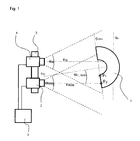
An invented device for measuring a slaughter animal body half 1 comprises an
image camera 2 and a depth camera 3.
The image camera 2 is an RGB camera and has an image-recording range with
a recording angle aRGB.
Within the image recording range, a cutting-side surface of the slaughter
animal
body half 1, here illustrated by the plane axis gsKH of the cutting-side
surface, can
be at least partially recorded by the image camera 2.
Within the image recording range, the image camera 2 can additionally record
light intensity values (g) of image points and their area coordinates (x, y)
on the
cutting-side surface of the slaughter animal body half 1.
The recorded light intensity value data and area coordinates are combined to
light intensity value data (x, y, g) and provided for transfer purposes by the
image
camera 2.
CA 02905533 2015-09-11
-16-
0366/15
According to the invention, the light intensity value data are transferred to
an
evaluation unit 3 which is connected to the image camera 2 and registers and
further processes the transferred light intensity value data.
The depth camera 4 intended by the invention is designed as a TOF (Time-of-
flight) camera and has a depth camera recording range with a recording
angle ail
Within the depth camera recording range, the cutting-side surface of the
slaughter animal body half 1 can also be at least partially recorded.
The depth camera 4 can simultaneously record space coordinates of image
points on the cutting-side surface of the slaughter animal body half 1, and
the
space coordinates always consist of the area coordinates (x, y) and a depth
value (z).
The space coordinates are provided by the depth camera 4 as space coordinate
data (x, y, z) and are also transferred to the evaluation unit 3 which is also
connected to the depth camera 4.
In the invention, the image camera 2 and the depth camera 4 are positioned
relative to each other by a positioning device 5 in such a way that the image
camera recording range and the depth camera recording range overlap at least
in certain sections in a common recording range that is as large as possible.
The evaluation unit 3 of the present invention is capable of using the light
intensity value data of the image camera 2 for identifying and defining
discrete
measurement points P1, P2 on the cutting-side surface of the slaughter animal
body half 1.
In this way, an object detection of defined areas on the cutting-side surface
of
the slaughter animal body half 1 is made possible such that, for example,
image
points with high light intensity value data are assigned to fat tissue
segments and
image points with low light intensity value data are assigned to meat tissue
CA 02905533 2015-09-11
-17-
0366/15
segments. On the basis of the different light intensity value data a concrete
differentiation between light-intensive and low-light image points and thus a
differentiation between fat and meat tissue sections can then be carried out
automatically.
The measurement points P1 and P2 are subsequently determined on the basis of
this information so that they mark, for example, the outer edges of a fat
tissue
section.
Furthermore, in the invention the evaluation unit 3 can assign the light
intensity
value data provided by the image camera 2 and the space coordinate data
provided by the depth camera 4 to each other via matching area coordinates and
thus determine the appropriate depth value for each measurement point P1, P2.
In addition to this, the evaluation unit 3 makes it possible to combine the
light
intensity value data and the space coordinates to data tuples, whereby one
data
tuple can always be assigned to each measurement point P1,P2, and it is
particularly advantageous that on the basis of the data tuples of the
measurement points P1, P2 the spatial distance between them can be
determined.
Thus, a particular technical advantage is provided by the measurement of the
cutting-side surface of the slaughter animal body half 1 and by an object
detection of relevant areas in the surface, for which the otherwise usual two-
dimensional area information is complemented by the depth value to enable a
three-dimensional object detection on the cutting-side surface of the
slaughter
animal body half.
In an inventive embodiment, the image camera 2 and the depth camera 4 are
positioned in relation to each other in such a way that the corresponding
recording ranges of the cameras overlap in a common recording range, at least
in certain sections.
CA 02905533 2015-09-11
-18-
0366/15
The image points are recorded in the common recording range in real time,
which means that no or only a slight relative movement of the slaughter animal
body half 1 relative to the device occurs between the recording of the
specific
image point by the image camera 2 and the recording of the same image point
by the depth camera 4.
The image camera 2 and the depth camera 4 are positioned in the invented
device such that the measurement standard nRGB of the image camera and the
measurement standard np of the depth camera are parallel to each other as far
as possible, and a distance d arises between the cameras such that a
sufficiently
large common recording range is provided.
During the measurement procedure, the slaughter animal body half 1 is passed
along the device on a movement axis gt by a transport unit, here designed as a
tube track (not shown).
Thanks to the inclusion of the individual depth values it is particularly
advantageous that it is not necessary to align the slaughter animal body half
1
precisely relative to the device during the measurement.
In fact, it is sufficient if the cutting-side surface of the slaughter animal
body
half 1 faces the image camera 2 and the depth camera 4 so that the relevant
measurement points P1, P2 can be clearly identified and a sufficiently high
resolution of image points is provided.
Compared with solutions known so far, the device according to this invention
therefore offers the technological advantages that a very exact measurement of
the cutting-side surface of the slaughter animal body half 1 and an exact
object
detection of relevant surface areas, such as fat, meat or bone tissue, can be
carried out automatically and that, simultaneously, by including the depth
values,
possible measurement irregularities caused by an imprecise positioning of the
slaughter animal body half 1 or by an existing unevenness of the cutting-side
surface of the slaughter animal body half 1 can be compensated.
CA 02905533 2015-09-11
-19-
0366/15
In Fig. 2 a further particularly advantageous embodiment of the invention is
shown and, for simplification purposes, the positioning device and the
movement
axis of the slaughter animal body half 1 are not illustrated anew.
The slaughter animal body half 1 shown in Fig. 2 has a real surface shape that
does not match a model-like ideal shape that is supposed to be a plane in the
embodiment. The deviation of the real surface shape is demonstrated by the
position of the first measurement point P1. The determined measurement
point P1 is therefore not positioned on the model-like ideal shape of the
cutting-
side surface, illustrated by a plane axis gsKH in Fig. 2.
Due to the deviation of the determined measurement point P1 from the idealized
cutting-side plane, a deviating distance of the measurement points in the
space
would arise on the basis of the real surface shape.
In order to reduce the inaccuracy caused by the measurement points deviating
from the ideal plane, the further embodiment shown in Fig. 2 is designed such
that several representative auxiliary points, here H1 to H3, are determined on
the
cutting-side surface of the slaughter animal body half 1 in a first step. In a
next
step, an idealized cutting-side plane, illustrated by the straight line gsKH,
is
defined on the basis of these auxiliary points H1 to H3.
Afterwards, the deviating measurement point P1 is projected onto the idealized
cutting-side plane and thus the projected measurement point P1' is created.
The
z-value, which corresponds to the z-value of the idealized cutting-side plane
in
the point of the corresponding area coordinates, is assigned to the
measurement
point P1.
A distance for the further use within a line segment and/or area measurement
can now be determined between the projected measurement point P1' and a
further determined measurement point P2 and thus a higher accuracy can be
achieved.
= CA 02905533 2015-09-11
- 20 -
0366/15
LIST OF REFERENCE NUMERALS
1 slaughter animal body half
2 image camera
3 evaluation unit
4 depth camera
nRGB measurement standard of image camera
np measurement standard of depth camera
nc measurement standard of slaughter animal body half
gSKH plane axis of slaughter animal body half
gt movement axis of slaughter animal body half
gn projection axis of first measurement point
aRGB recording angle of image camera
ao recording angle of depth camera
aC,RGB angle between slaughter animal body half and image camera
P1 first measurement point
P2 second measurement point
P1' projected first measurement point on ideal surface
H1 first auxiliary point
H2 second auxiliary point
H3 third auxiliary point