Note : Les descriptions sont présentées dans la langue officielle dans laquelle elles ont été soumises.
CA 02906509 2015-09-14
WO 2014/150956
PCT/US2014/024646
ELASTOMERIC EXTRACTOR MEMBER
FIELD OF THE INVENTION
[0001] The present invention generally relates to firearms and components
thereof,
and in particular, to an elastomeric biasing member for operation of an
extractor of a
firearm.
BACKGROUND OF THE DISCLOSURE
[0002] Many firearms, including bolt action, semiautomatic, and/or fully
automatic
firearms utilize a pivoting-type extractor system for extraction of cartridges
from the
firearm chamber. Typically, such conventional pivoting extractor systems will
include an arm or elongated body generally engaged at one end by a spring that
provides a biasing force to urge the extractor into engagement with a
cartridge in the
firearm chamber. These springs usually are made from metal and are subjected
to
repeated stresses, high heat, and vibration during use of the firearm which
may result
in premature failure. For example, the biasing force often provided through a
coiled
metallic spring can undergo a number of cycles where it is compressed, and
then may
relax, while at the same time being exposed to repeated heating and cooling
cycles.
[0003] Accordingly, a need exists for an extractor mechanism that
addresses these
and other drawbacks.
SUMMARY OF THE DISCLOSURE
[0004] In one aspect, the disclosure is generally directed to a biasing
member for a
pivoting extractor of a firearm. The biasing member comprises a body having a
first
portion configured to engage and seat within a biasing member receiving
indentation
of a bolt assembly of the firearm and a second portion configured to provide a
biasing
force to the pivoting extractor. The body of the biasing member includes a
geometry
configured to provide controlled extractor tensions through a range of motion
of the
pivoting extractor. The body of the biasing member can further consist
essentially of
an elastomeric material.
1
CA 02906509 2015-09-14
WO 2014/150956
PCT/US2014/024646
[0005] In another aspect, the disclosure is generally directed to a bolt
assembly for a
firearm. The bolt assembly comprises a bolt, an extractor arm pivotally
mounted in
the bolt and having a biasing member receiving indentation formed thereon, and
a
biasing member in mechanical communication with the extractor arm. The biasing
member has a body engaged within the biasing member receiving indentation, and
is
configured to provide a biasing force against the bolt and extractor arm. The
body can
also consist essentially of an elastomeric material.
[0006] In yet another aspect, the disclosure is generally directed to a
firearm. The
firearm can include a bolt assembly having a pivoting extractor and a biasing
member
in communication with the pivoting extractor. The biasing member comprises a
body
having a first cylindrical portion mounted in the extractor and a second
cylindrical
portion external to the pivoting extractor configured to provide a biasing
force to the
pivoting extractor. The body further can consist essentially of an elastomeric
material.
[0007] Those skilled in the art will appreciate the above stated advantages
and other
advantages and benefits of various additional embodiments reading the
following
detailed description of the embodiments with reference to the below-listed
drawing
figures.
BRIEF DESCRIPTION OF THE DRAWINGS
[0008] According to common practice, the various features of the drawings
discussed
below are not necessarily drawn to scale. Dimensions of various features and
elements in the drawings may be expanded or reduced to more clearly illustrate
the
embodiments of the disclosure.
[0009] FIG. 1A illustrates a firearm.
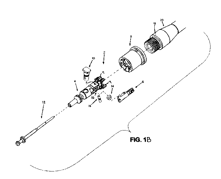
[0010] FIG. 1B is an exploded fragmented isometric view of a bolt assembly
also
showing a portion of a firearm barrel of the firearm of FIG. 1A.
[0011] FIG. 2 further illustrates the bolt assembly of FIG. 1B.
2
CA 02906509 2015-09-14
WO 2014/150956
PCT/US2014/024646
[0012] FIGS. 3A-3B illustrate details of the bolt extractor of FIGS. 1-2.
[0013] FIG. 4 is an isometric view of a biasing member useable with the
bolt
assembly of FIGS. 1-2 and the bolt extractor of FIGS. 3A-3B, according to an
embodiment of the invention.
[0014] FIG. 5 is an elevation view of the biasing member of FIG. 4.
[0015] FIG. 6 is a top view of the biasing member of FIG. 4.
[0016] FIG. 7 is a cut-away view of an assembled carrier assembly
illustrating
positioning of the biasing member of FIG. 4.
[0017] Corresponding parts are designated by corresponding reference
numbers
throughout the drawings.
DETAILED DESCRIPTION OF THE EXEMPLARY EMBODIMENTS
[0018] Referring now to the drawings in which like numerals indicate like
parts
throughout the several views, the present invention generally is directed to
components of firearms including biasing members suitable for direct
replacement in
a plurality of firearms. In particular, in one embodiment, the present
invention
includes a biasing member having a geometry and material selection which
provides
higher and/or constant extractor tension during operation of a firearm. It
will be
understood by those skilled in the art that the present invention can be
adapted for use
with various types of firearms, including various types of semi-automatic,
automatic,
and manually operable rifles, shotguns and/or other long guns, as well as
various types
of handguns.
[0019] FIG. lA illustrates an example firearm F, having a bolt assembly 2
and FIG.
1B is an exploded fragmented isometric view of the bolt assembly 2 aligned
with a
portion of a firearm barrel 20 with which it is moved into locking engagement.
Referring in detail to FIG. 1B, the bolt assembly 2 generally comprises bolt
4, bolt
head 5, extractor 6, barrel extension 8, cam pin 10, firing pin 12, biasing
member 14,
3
CA 02906509 2015-09-14
WO 2014/150956
PCT/US2014/024646
and extractor pivot pin 16. The bolt assembly 2 engages and locks into the
barrel
extension 8 through a series of lugs 9 arranged about the bolt head 5 of the
bolt 4 and
onto the rear end 18 of firearm barrel 20. The extractor pivot pin 16 may be
received
in a pivot bore 15 to allow pivoting of the extractor 6.
[0020] FIG. 2 further illustrates the bolt assembly of FIG. IB from a
further
perspective. As illustrated, the biasing member 14 may be engaged with the
bolt 4
proximate the pivot bore 15 and may be further engaged with the extractor 6.
[0021] As indicated in FIG. 1A, the entire bolt assembly 2 may be loaded
into the
firearm F for operation of the firearm. The firearm will include the barrel 20
which is
engaged by the bolt assembly 2. The firearm may also further include an upper
receiver 28 connected to a lower receiver 29. The firearm may also further
include a
stock 21 and grip 22 mounted to the upper and lower receiver 28, 29. The lower
receiver may include a trigger 26 arranged in a trigger guard 27 and a
magazine well
23 for receiving a magazine. The firearm also may further include a hand guard
24
attached to the upper receiver 28 and surrounding at least a portion of the
barrel 20.
The firearm F and associated features 2, 4, 5, 6, 8, 10, 12, 14, 15, 16, 18,
20, 21, 22,
23, 24, 26, 27, 28, and 29 may be otherwise arranged, shaped, configured,
and/or
omitted depending upon a particular firearm implemented and without departing
from
the scope of this disclosure.
[0022] FIGS. 3A-3B illustrate further details of the extractor 6 of FIGS.
1-2. As
shown, the extractor 6 includes an elongated extractor arm or body 30 having a
first
distal end 35, a second distal end 36, and a pivot region 37 arranged
therebetween.
The extractor arm 30 includes a claw or cartridge indentation portion 31 for
cartridge
extraction adjacent the first distal end 35. The extractor arm 30 further
includes a
biasing member receiving indentation or seat/recess 33 adjacent the second
distal end
36 configured to receive a portion of the biasing member 14. The extractor arm
30
further includes an annular flange region 34 about the biasing member
receiving
indentation 33, configured to support a portion of the biasing member 14. A
pivot
recess or through-hole 32 also is formed in the extractor arm adjacent the
pivot region
4
CA 02906509 2015-09-14
WO 2014/150956
PCT/US2014/024646
37. In general, the biasing member receiving indentation 33 may be an indented
formation extending from the annular flange region 34 into an interior of the
elongated body 30 at the second distal end 36. The biasing member receiving
indentation 33 may have a radial dimension R1 and the annular flange region 34
may
have a radial dimension R2. Furthermore, the pivot recess 32 may be a through
hole
configured to receive the extractor pivot pin 16. The elongated extractor body
30 and
associated features 31, 32, 33, 34, 35, 36, and 37 may be otherwise shaped or
configured without departing from the scope of this disclosure.
[0023] As described above, the biasing member receiving indentation 33
and the
annular flange 34 may be configured to receive and support the biasing member
14,
respectively. Hereinafter, the biasing member 14 is described in detail with
reference
to FIGS. 4-7.
[0024] FIG. 4 is an isometric view of the biasing member 14 useable with
the bolt
assembly of FIGS. 1-2 and the bolt extractor of FIGS. 3A-3B, according to an
embodiment of the invention. The biasing member 14 comprises a body generally
indicated at 40.
[0025] According to one embodiment of the invention, the body 40 of the
biasing
member consists essentially of an elastomeric material. The elastomeric
material may
comprise any suitable material. For example, according to one embodiment, the
elastomeric material may be comprised of elastomeric polymer units containing
silicone, fluorosilicone, or fluorocarbon, not to exclude thermoplastic or
thermoset
elastomers known in the art including any saturated and/or unsaturated rubbers
that
can be formed into a part of a defined geometry upon curing. If the polymer is
amorphous and has a glass-transition temperature below use temperature, then
the
polymer is considered an elastomer for this purpose.
[0026] According to one embodiment, an elastomeric polymer unit as
described
above can be as shown by Formula I, produced below:
CA 02906509 2015-09-14
WO 2014/150956
PCT/US2014/024646
( Si ¨O )
Formula I:
[0027] In accordance with Formula I, R can be CH3 (giving a silicone) or
R can be F,
CF3, and/or CH2CF2CF3 (giving a fluorosilicone).
[0028] According to another embodiment, an elastomeric polymer unit as
described
above can be as shown by Formula II, produced below:
R R
iI
C C _______________________________
)n
Formula II: R R
[0029] In accordance with Formula II, R can be F and/or CF3 (giving a
fluorocarbon).
[0030] With reference to FIGS. 3B and 4-6, the body 40 of the biasing
member 14 is
shown in further detail. In general, a geometry of the annular flange region
44 and the
interface of annular surface 34 provides control of extractor tension through
a range of
motion of the arm 30 of the extractor 6. As indicated in Figs. 4-7 the biasing
member
body 40 includes a first cylindrical portion 43 configured to seat within and
be
engaged with the biasing member receiving indentation 33 of the extractor 6.
An
annular flange region 44 extends radially from the first cylindrical portion
43 and will
be configured to be supported by the annular flange region 34 of the extractor
6. The
body 40 further includes a second cylindrical portion 45 adjacent the annular
flange
region 44 and extending longitudinally therefrom such that it is external to
the
extractor body 30. The body 40 further includes a convex distal end 46
adjacent the
second cylindrical portion 45, and a convex distal end 47 adjacent the first
cylindrical
portion 43. The first and second cylindrical portions 43 and 45 further will
include
peripheral side walls 48 and 49, respectively, as shown in Figs. 5-6.
6
CA 02906509 2015-09-14
WO 2014/150956
PCT/US2014/024646
[0031] Generally, the interaction of the features of the body during a
compression
cycle, including the convex distal ends 46, 47, the annular flange region 44,
and the
first and second cylindrical portions 43, 45 are such that the first and
second portions
43, 45 and the body 40 of the biasing member in general provide varying levels
of
compression sufficient to maintain a desired extractor tension with a
cartridge as the
extractor is pivoted during an extraction cycle. For example, the elastomeric
material
comprising the body 40 of the biasing member and the defined geometry of the
body
40 of the biasing member provide for relatively a different level of
compression, and
thus the biasing force created thereby when the extractor arm 30 is initially
pivoted
outwards relative to the bolt head 5 versus the level/amount of compression as
the
extractor arm is pivoted further against the body. Furthermore, as the body 40
is
comprised of elastomeric material, it generally lacks a minimum or "bottom-
out"
dimension as with a conventional spring, and therefore provides a constantly
biasing
force (which may vary depending upon overall compression of the body 40)
throughout the pivoting motion of the arm 30 of the extractor 6. The body 40
of the
biasing member and the associated features 43, 44, 45, 46, and 47 thereof may
be
otherwise shaped, arranged, and/or omitted without departing from the scope of
this
disclosure.
[0032] As illustrated in FIG. 5, the convex distal end 47 has an overall
longitudinal
dimension Dl and the first cylindrical portion 43 has an overall longitudinal
dimension D2. According to one embodiment of the invention, the sum of the
dimensions Dl and D2 is approximately equal to a total depth of the biasing
member
receiving indentation 33 of the extractor arm 30. According to another
embodiment,
the sum of the dimensions Dl and D2 is slightly larger than the total depth of
the
biasing member receiving indentation 33 of the extractor arm 30. As further
illustrated in FIG. 5, the second cylindrical portion 45 has an overall
longitudinal
dimension D3 and the convex distal end 46 has an overall longitudinal
dimension D4.
According to one embodiment, the sum of the dimensions D3 and D4 is such that
an
appropriate biasing force is provided by the body 40 of the biasing member
against the
extractor arm 30 when assembled into an at least partially functional bolt
assembly.
7
CA 02906509 2015-09-14
WO 2014/150956
PCT/US2014/024646
The longitudinal dimensions of the body 40 of the biasing member as indicated
at D1,
D2, D3, and D4 in Fig. 5, may be otherwise increased, decreased, maximized,
and/or
minimized without departing from the scope of this disclosure.
[0033] As illustrated in FIG. 6, the first cylindrical portion 43 has a
radial dimension
of R3 which is approximately equal to the radial dimension R1 of the biasing
member
receiving indentation 33 of the extractor arm 30, according to one embodiment.
Furthermore, the annular flange 44 has a radial dimension of R4 which is
approximately equal to the radial dimension R2 of the annular flange region 34
of the
extractor arm 30, according to another embodiment. According to one
embodiment,
radial dimension R4 (corresponding to a radial dimension of the second
cylindrical
body 45) is larger than the radial dimension R3. The radial dimensions of the
body 40
of the biasing member including radii R3 and R4 shown in FIG. 6 may be
otherwise
increased or decreased, without departing from the scope of this disclosure.
[0034] As described above, the biasing member 14 may be assembled into a
carrier 3
of the bolt assembly 2 of a firearm. Furthermore, the biasing member may be a
suitable replacement for conventional coiled-spring configurations of known
biasing
members. For example, FIG. 7 is a cut-away view of an assembled bolt carrier
assembly 3 illustrating positioning of the biasing member 14. As illustrated,
the
biasing member 14 is in mechanical communication with the bolt 4 and the
pivoting
arm 30 of the extractor 6. The body of the biasing member is received and
mounted
within a recess or receiving area 51 along the bolt 4, with the peripheral
side wall 49
of the second cylindrical portion 45 of the body 40 of the biasing member
contacting
and/or being bordered by the sides 52A/52B of the receiving area/recess 51.
Furthermore, the biasing member 14 provides a biasing force to the pivoting
arm 30 of
the extractor 6 to maintain a substantially constant extractor tension between
the
cartridge indentation portion or claw 31 and a cartridge during rest and when
pivoting
such as during loading and/or extraction cycles.
[0035] For example, as the extractor arm pivots in a direction Al, such
as during a
loading cycle, the biasing member 14 is compressed in the direction A2.
Generally,
8
CA 02906509 2015-09-14
WO 2014/150956
PCT/US2014/024646
the biasing member 14 resists this compression and provides a biasing force
against
the extractor arm responsive thereto. As the extractor arm further pivots in
the
direction Al and the biasing member 14 is compressed in the direction A2, the
biasing
member 14 also can be extended in a lateral direction indicated by arrows A3.
Generally, the engagement of side wall 49 of the second cylindrical portion 45
of the
body with the walls 52A/52B of the receiving area/recess 51 of the bolt 4
resists this
lateral deformation and provides a counter biasing force responsive thereto.
Thus, as
shown, due to the second portion 45 of the body 40 being constrained by the
receiving
area/region 51 and its further extending into the region 34 of the extractor
arm 30 by
way of the annular flange region 44 during an extraction operation, the
biasing
member 14 remains in positive communication with the extractor arm throughout
its
pivoting motion without "bottoming out." As a result, a consistent biasing
force is
provided against the extractor arm, in turn creating a substantially constant
extractor
tension enabling the extractor arm to maintain positive contact between the
cartridge
indentation portion or claw 31 and the cartridge in the firearm. It should be
readily
understood that although illustrated here as being a general firearm, the
biasing
member 14 may be dimensioned and arranged for use in biasing any suitable
pivoting
extractor of any suitable firearm, including long guns, rifles, handguns,
shotguns, or
any other firearm having a pivoting extractor.
[0036] The foregoing description generally illustrates and describes
various
embodiments of the present invention. The examples given above are merely
illustrative and are not meant to be an exhaustive list of all possible
designs, aspects,
applications or modifications of the present disclosure. It will, therefore,
be
understood by those skilled in the art that while the present disclosure has
been
described in terms of exemplary aspects, the present disclosure can be
practiced with
various changes and modifications which can be made to the above-discussed
construction of the present invention without departing from the spirit and
scope of
the invention as disclosed herein, and that it is intended that all matter
contained in the
above description or shown in the accompanying drawings shall not to be taken
in a
limiting sense.
9
CA 02906509 2015-09-14
WO 2014/150956
PCT/US2014/024646
[0037] Furthermore, the scope of the present disclosure shall be
construed to cover
various modifications, combinations, additions, alterations, etc., to the
above-
described embodiments, which shall be considered to be within the scope of the
present invention. Accordingly, various features and characteristics of the
present
invention as discussed herein may be selectively interchanged and applied to
other
illustrated and non-illustrated embodiments of the invention, and numerous
variations,
modifications, and additions further can be made thereto without departing
from the
spirit and scope of the present invention.