Note : Les descriptions sont présentées dans la langue officielle dans laquelle elles ont été soumises.
CA 02912574 2015-11-13
ROCK FACE SPLITTING APPARATUS AND METHOD
TECHNICAL FIELD
[0002] The present disclosure relates to masonry blocks,
and more specifically to a masonry block splitting apparatus
and method that creates a convex, or "rock-like" split face
without the need for projections and the associated cleaning.
BACKGROUND OF THE INVENTION
[0003] Block splitting methods and apparatuses typically
include splitters with projections to generate split blocks
with a roughened look. These projections get fouled easily,
and need to be frequently cleaned.
SUMMARY OF THE INVENTION
[0004] A splitting apparatus is provided that includes a
first splitting blade with a smooth top that forms a blade
edge. The smooth top has a width X and a shoulder angle of
less than the friction angle from a point in the middle of
the top. A second splitting blade is disposed opposite the
first splitting blade, and has a smooth top with a width Y
and a shoulder angle of less than the friction angle from a
point in the middle of the top.
1
CA 02912574 2015-11-13
[0004a] Accordingly then, in one aspect, there is provided
a splitting apparatus comprising: a press configured to apply
a force to a masonry block; an assembly on which the masonry
block rests; a first splitting blade having a smooth top with
a width X and a shoulder angle of less than the friction
angle, relative to a point in the middle of the top; and a
controller coupled to the press and a conveyor and configured
to advance the masonry block over the first splitting blade
to cause the masonry block to wipe debris from the splitting
blade.
[0004b] In another aspect, there is provided a method of
processing masonry blocks, comprising: crushing an edge of a
masonry block against a stationary smooth surface having an
incline of less than a friction angle until debris is
generated; and wiping the debris from the smooth surface by
sliding the masonry block over the surface.
[0004c] In a further aspect, there is provided a method of
cleaning masonry splitter blades comprising: pushing a first
masonry block towards a block-engaging blade surface; sliding
the first masonry block over the block-engaging blade surface
having shoulder angles less than the friction angle; and
removing debris from the block engaging blade surface by
repeating the pushing and sliding steps.
la
CA 02912574 2015-11-13
[0004d] In a still further aspect, there is provided a
method of positioning a masonry block for splitting
comprising: positioning the masonry block between an upstream
block and a downstream block; moving the masonry block onto
a fixed, raised blade edge; and aligning the masonry block
for splitting with the upstream block and the downstream
block.
[0004e] In a yet another aspect, there is provided in a
splitting apparatus having a first splitting blade having a
smooth top with a width X and a shoulder angle of less than
a friction angle of a masonry block to be split, relative to
a point in the middle of the top and a second splitting blade
disposed opposite the first splitting blade, the second
splitting blade having a smooth top with a width Y and a
shoulder angle of less than the friction angle of the masonry
block to be split, relative to a point in the middle of the
top, a blade support with a channel, wherein the first
splitting blade is disposed within the channel, wherein the
first splitting blade further comprises a plurality of
segments, each having a length L and a width W, a blade
support with a channel, a metal strip disposed within the
channel, wherein the first splitting blade is disposed within
the channel on top of the metal strip, an infeed plate
adjacent to the first splitting blade, with a predetermined
gap between the infeed plate and the first splitting blade,
an outfeed plate adjacent to the first splitting blade, with
a predetermined gap between the outfeed plate and the first
lb
CA 02912574 2015-11-13
splitting blade, wherein the blade support comprises a first
shoulder disposed on a first side of the first splitting blade
and a second shoulder disposed on a second side of the first
splitting blade, wherein the first splitting blade further
comprises a first top surface and a second top surface that
meet at the point in the middle of the top, wherein the first
top surface intersects with a first side surface and the
second top surface intersects with a second side surface, and
wherein the intersection between the first top surface and
the first side is flush with a first shoulder of the blade
support, a method of splitting masonry blocks, comprising:
actuating a lifting mechanism to lift an array of masonry
blocks from a pallet; transferring the array of masonry blocks
to a conveyor device; engaging a motive element of the
conveyor device; moving the array of masonry blocks along the
conveyor device to a splitting mechanism; pushing a first row
of masonry blocks over the first splitting blade that extends
into a plane of the conveyor; releasing the motive element
after the first row of masonry blocks is centered on the first
splitting blade; splitting the first row masonry blocks;
pressing a surface of a masonry block against a smooth surface
that has an incline of less than a friction angle of the
concrete block until debris is generated; cleaning the smooth
surface of the debris by pushing the masonry block over the
surface; re-engaging the motive element; wiping an outfeed
edge of the first splitting blade with a rear corner of the
first row of masonry blocks; wiping an infeed edge of the
first splitting blade with a front corner of a second rock of
masonry blocks, wherein splitting the first row of masonry
lc
CA 02912574 2015-11-13
blocks comprises moving the second splitting blade towards
the first splitting blade while holding the bottom splitting
blade stationary; crushing an edge of a masonry block against
a smooth surface having an incline of less than a friction
angle until debris is generated; wiping the debris from the
smooth surface by sliding the masonry block over the surface;
wherein a hydraulic press produces the crushing action, a
powered conveyor produces the sliding action, the crushing
action and sliding action are approximately orthogonal, the
smooth surface comprises pulverized concrete, the smooth
surface further comprises one or more features for retaining
pulverized concrete from the debris; pushing a first masonry
block towards a block-engaging blade surface; sliding the
first masonry block over the block-engaging blade surface
having shoulder angles less than the friction angle; removing
debris from the block engaging blade surface by repeating the
pushing and sliding steps; positioning the masonry block
between an upstream block and a downstream block; moving the
masonry block onto a fixed, raised blade edge; and aligning
the masonry block for splitting with the upstream block and
the downstream block.
id
= CA 02912574 2015-11-13
W02015474021 PCTMS2014/066071
[0005] Other systems, methods, features, and advantages of
the present disclosure will be or become apparent to one with
skill in the art upon examination of the following drawings and
detailed description. It is intended that all such additional
systems, methods, features, and advantages be included within
this description, be within the scope of the present disclosure,
and be protected by the accompanying claims.
BRIEF DESCRIPTION OF THE SEVERAL VIEWS OF THE DRAWINGS
[0006] Aspects of the disclosure can be better understood
with reference to the following drawings. The components in the
drawings are not necessarily to scale, emphasis instead being
placed upon clearly illustrating the principles of the present
disclosure. Moreover, in the drawings, like reference numerals
designate corresponding parts throughout the several views, and
in which:
[0007] FIGURE 1 is a diagram of a block splitting apparatus
for creating a convex split face in accordance with an exemplary
embodiment of the present disclosure;
[0008] FIGURE 2 is a diagram of a block splitting apparatus
loaded with a masonry block, in accordance with an exemplary
embodiment of the present disclosure;
[0009] FIGURE 3 is a diagram of a block splitting apparatus
with a split in a masonry block, in accordance with an exemplary
embodiment of the present disclosure;
[0010] FIGURE 4 is a diagram of a block splitting apparatus
loaded with a split masonry block, in accordance with an
exemplary embodiment of the present disclosure;
[0011] FIGURE 5 is a diagram of a block splitting apparatus
loaded with a split masonry block and retracted splitting blade,
CA 02912574 2015-11-13
W02015/074021 PCT/US2014/066071
in accordance with an exemplary embodiment of the present
disclosure;
[0012] FIGURE 6 is a diagram of a block splitting apparatus
loaded with a masonry block, in accordance with an exemplary
embodiment of the present disclosure;
[0013] FIGURE 7A is a diagram of a bottom splitting blade
assembly, in accordance with an exemplary embodiment of the
present disclosure;
[0014] FIGURE 7B is a diagram of a top splitting blade
assembly, in accordance with an exemplary embodiment of the
present disclosure;
[0015] FIGURE 70 is a side view of a top splitting blade
assembly, in accordance with an exemplary embodiment of the
present disclosure;
[0016] FIGURE 7D is a detail view of a bottom splitting blade
segment, showing shoulder angle a relative to the peak of a
bottom splitting blade segment;
[0017] FIGURE 7E is a detail view showing debris that has
accumulated on the infeed edge surface of a bottom splitting
blade segment, which is in the process of being wiped by the
leading edge of a masonry block;
[0018] FIGURE 7F is a detail view showing debris that has
accumulated on the outfeed edge surface of a bottom splitting
blade segment, which is in the process of being wiped by the
trailing edge of a masonry block;
[0019] FIGURE Ei is a flow chart of an algorithm for splitting
masonry blor7ks, in accordance with an exemplary embodlment of
the present disclosure;
[0020] FIGURE 9 is a force diagram in accordance with an
exemplary embodiment of the present disclosure;
CA 02912574 2015-11-13
W02015/074021 PCT/US2014/066071
[0021] FIGURE
10 is a diagram of splitting blade structures
in accordance with an exemplary embodiment of the present
disclosure;
[0022] FIGURE
11A is a diagram showing an edge texturing
configuration prior to the application of pressure, in
accordance with an exemplary embodiment of the present
disclosure; and
[0023] FIGURE
113 is a diagram showing an edge texturing
configuration after the application of pressure, in accordance
with an exemplary embodiment of the present disclosure.
DETAILED DESCRIPTION OF THE INVENTION
[0024] In the
description that follows, like parts are marked
throughout the specification and drawings with the same
reference numerals. The
drawing figures might not be to scale
and certain components can be shown in generalized or schematic
form and identified by commercial designations in the interest
of clarity and conciseness.
[0025] FIGURE
I is a diagram of a block splitting apparatus
100 for creating a convex split face in accordance with an
exemplary embodiment of the present disclosure.
Apparatus 100
can be used in conjunction with a block handling machine that
places an assembly of whole concrete blocks on a conveyor, a
conveyor system that moves the whole concrete blocks to a
hydraulic press that has been fitted with block splitting
blades, a conveyor assembly that moves the split blocks and
other suitable equipment.
[0026]
Apparatus 100 includes upper splitting blade 104 and
lower splitting blade 106, which can each be formed from one or
more of tungsten carbide, hardened AR steel or other suitable
materials, and which can each have a smooth surface with no
4
CA 02912574 2015-11-13
W02015/074021 PCT/US2014/066071
protrusions. Upper
splitting blade 104 and lower splitting
blade 106 can each have shallow shoulder angles and preferably
have shoulder angles that are less than the friction angle. If
the shoulder angle is less than the friction angle, then the
splitting blade will hold the masonry block in position as it is
being split, and will crush the edges of the masonry block to
create a convex split face.
Conversely, if the shoulder angle
is greater than the friction angle, then the masonry block
halves will, after the initial fracture, be squeezed away from
the splitting blade with little or no split face convexity.
[0027] For
most masonry materials, the friction angle is
typically 15 to 20 degrees, but if the shoulder angle is less
than about 5 degrees, then the debris from splitting operations
can impede the subsequent process. In one exemplary embodiment,
upper splitting blade 104 can be approximately 30 mm wide with a
shoulder angle of approximately 10 degrees, and lower splitting
blade 106 can be approximately SO mm wide with a shoulder angle
of approximately 10 degrees, although other widths and shoulder
angles can also or alternatively be used.
[0028] FIGURE 2
is a diagram of block splitting apparatus 100
loaded with masonry block 102, in accordance with an exemplary
embodiment of the present disclosure. Block 102 is pushed into
position by an adjacent block (not explicitly shown). The
placement of block 102 can be controlled by an operator, by
using optical or mechanical sensors, or in other suitable
manners, in order to align splitting blades 104 and 106 with
bl.ock 12 to a predetermined locaton. Although splitting blade
106 protrudes slightly from the top surfaces of blade holder
110, block 102 does not lean towards one side, because it is
held in position by the adjacent blocks.
[0029] FIGURE 3
is a diagram of block splitting apparatus 100
Loaded with a split 202 in masonry block 102, in accordance with
CA 02912574 2015-11-13
W02015/074021 PCT/US2014/066071
an exemplary embodiment of the present disclosure. When
block
102 is in position and upper splitting blade 104 is moved
towards lower splitting blade 106, tension is induced in block
102 along the plane connecting the edges of splitting blades 104
and 106. A
vertical fracture 202 then occurs in block 102,
representing a tension-induced failure of block 102.
[0030] FIGURE 4
is a diagram of block splitting apparatus 100
loaded with split masonry block 102, in accordance with an
exemplary embodiment of the present disclosure. After vertical
fracture 202 is formed in masonry block 102, the angled shoulder
surfaces of splitting blades 104 and 106 then cause spalling of
the block portions along the intersections of the split plane
with the upper and lower surfaces of block 102 to form a convex
split face. Although the angled shoulder surfaces of splitting
blades 104 and 106 are smooth, the heterogeneous properties of
the concrete create an irregular texture similar to that of the
original vertical split.
[0031] Once the
action of upper splitting blade 104 is
completed, the split halves of the masonry block 102 are
squeezed away from each other, which stops further spalling to
the block portions along the intersections of the split plane
with the upper and lower surfaces of block 102. In
addition,
some debris can be generated at that time, but the majority of
the debris will be held in place by the split halves of masonry
block 102.
[0032] FIGURE 5
is a diagram of block splitting apparatus 100
loaded with a split masonry block 102 and retracted upper
splitting blade 104, in accordance with an exemplary embodiment
of the present disclosure. The
debris formed by the splitting
operation is not explicitly shown.
[0033] FIGURE 6
is a diagram of block splitting apparatus 100
loaded with masonry block 102, in accordance with an exemplary
6
= CA 02912574 2015-11-13
W02015/074021 PCT/US2014/066071
embodiment of the present disclosure. After the splitting
operation is completed, the split pieces of block 102 are pushed
towards outfeed plate 112, and a new block 102 is moved in
behind the split block 102.
As shown in FIGURE 6, the front
block 102 is elevated slightly relative to the rear block 102,
as it rides over lower splitting blade 106.
The sliding
movement of the blocks cleans debris from the angled shoulder
surfaces of lower splitting blade 106, as discussed in greater
detail below. The surfaces of lower splitting blade 106 are
smooth and easily cleaned by this sliding action, which
preserves the geometry of the apparatus, without fouling or
loading, for consistent results on subsequent splits.
[0034]
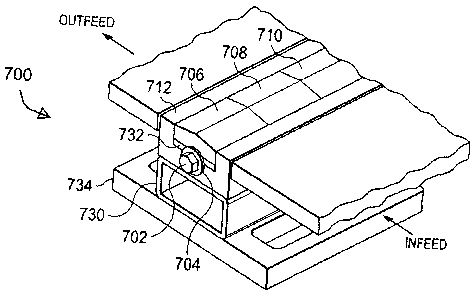
FIGURE 7A is a diagram of a bottom splitting blade
assembly 700, in accordance with an exemplary embodiment of the
present disclosure.
Bottom splitting blade assembly 700
includes base plate 734, which blade support 730 is coupled to,
such as with bolts or in other suitable manners.
Blade holder
712 is coupled to blade support 730, such as with bolts or in
other suitable manners, and includes a U-shaped channel that
holds a plurality of blade segments 706, 708 and 710.
Additional blade segments can also or alternatively be provided.
In one exemplary embodiment, each blade segment is approximately
2" wide (W) by 2" long (L) by 0.5" high (H), although other
suitable configurations can also or alternatively be used. A
metal strip 732 formed from brass, aluminum or other soft metal
or material, is used to accommodate variations in the
dimensional tolerances of each of the blade segments and is also
placed within the U-shaped channel.
[0035] The top of each blade segment includes a first fla
surface and a second flat surface that meet at a point to form
the blade edge. Each flat surface of the top of each blade
segment extends downwards at an angle of approximately 7.0
7
CA 02912574 2015-11-13
WO 2015/074021 PCT/US2014/066071
degrees, although variations within approximately 5 to 15
degrees can also or alternately be used. At each
side of the
blade segment, the top surface interfaces with a side surface to
form an edge, where the edge is typically configured to be flush
with the top surfaces of blade holder 712. Each top surface of
blade holder 712 is adjacent with a plate, such as an infeed
plate and an outfeed plate, which are used to guide the masonry
blocks into position onto bottom splitting blade assembly 700.
The top surfaces of blade holder 712 are configured to bear the
load of the masonry blocks during splitting, in order to reduce
deflection and wear on the infeed and outfeed plates.
[0036] FIGURE
73 is a diagram of a top splitting blade
assembly 750, in accordance with an exemplary embodiment of the
present disclosure. Top
splitting blade assembly 750 includes
base plate 720, which blade support 722 is coupled to, such as
with bolts 724 or in other suitable manners. Blade
726 is
coupled to blade support 722, such as with bolts 728 or in other
suitable manners. In one
exemplary embodiment, blade 726 is
approximately 30 mm wide by 1000 mm long by 15 mm high, although
other suitable configurations can also or alternatively be used.
[0037] FIGURE
7C is a side view of top splitting blade
assembly 750, in accordance with an exemplary embodiment of the
present disclosure.
[0038] FIGURE
7D is a detail view of a bottom splitting blade
segment 706, showing shoulder angle a relative to the peak of
bottom splitting blade segment 706. The blade portion of bottom
splitting blade segment 706 is elevated above the top s-,Irfaces
of blade holder 712, the infeed plate and the outfeed plate.
[0039] FIGURE
7E is a detail view showing debris that has
accumulated on the infeed edge surface of bottom splitting blade
segment 706, which is in the process of being wiped by the
leading edge of masonry block 102. As
masonry block 102 is
CA 02912574 2015-11-13
WO 2015/074021 PCT/US2014/066071
pushed forward by the conveyor, the edge of masonry block 102 is
pushed up the smooth surface of the infeed edge of bottom
splitting blade segment 706, which wipes the debris from the
previous splitting operation away.
Although this debris is
pushed to the outfeed edge surface of bottom splitting blade
segment 706, the amount of debris from a single splitting
operation is relatively small, and is subsequently cleaned as
discussed below.
[0040] FIGURE
7F is a detail view showing debris that has
accumulated on the outfeed edge surface of bottom splitting
blade segment 706, which is in the process of being wiped by the
trailing edge of masonry block 102. As
masonry block 102 is
pushed forward by the next masonry block (not shown), the
trailing edge of masonry block 102 is pushed down the smooth
outfeed edge surface of bottom splitting blade segment 706,
which wipes the debris from the previous splitting operation
away.
[0041] FIGURE
8 is a flow chart of an algorithm 800 for
splitting masonry blocks, in accordance with an exemplary
embodiment of the present disclosure.
Algorithm 800 can be
implemented in hardware, as one or more software systems
operating on a programmable controller or in other suitable
manners.
[0042] As used herein, "hardware" can include a combination
of discrete components, an integrated circuit, an application-
specific integrated circuit, a field programmable gate array, or
other suitable hardware. As used herein, "software" can include
one or more objects, agents, threads, lines of code,
subroutines, separate software applications, two or more lines
of code or other suitable software structures operating in two
or more software applications, on one or more processors (where
a processor includes a microcomputer or other suitable
CA 02912574 2015-11-13
W02015/074021 PCT/US2014/066071
controller, memory devices, input-output devices, displays, data
input devices such as a keyboard or a mouse, peripherals such as
printers and speakers, associated drivers, control cards, power
sources, network devices, docking station devices, or other
suitable devices operating under control of software systems in
conjunction with the processor or other devices), or other
suitable software structures. In one
exemplary embodiment,
software can include one or more lines of code or other suitable
software structures operating in a general purpose software
application, such as an operating system, and one or more lines
of code or other suitable software structures operating in a
specific purpose software application. As used herein, the term
"couple" and its cognate terms, such as "couples" and "coupled,"
can include a physical connection (such as a copper conductor),
a virtual connection (such as through randomly assigned memory
locations of a data memory device), a logical connection (such
as through logical gates of a semiconducting device), other
suitable connections, or a suitable combination of such
connections.
[0043]
Algorithm 800 begins at 802, where an array of blocks
is moved to a conveyor. In one
exemplary embodiment, blocks
that are manufactured by a block manufacturing process can be
stacked on pallets in a layered array, such as an 8 x 4 array,
and a block handling machine can be used to move individual
layers of the array to a conveyor system. The block handlin=
ma7hire can include a programmable controller, sensors,
hydraulic calipers and other suitable devices that allow the Lop
layer of the array of blocks to be located, to center the
calipers on the array, to close the calipers with sufficient
pressure to hold the array in place without crushing the
individual masonry blocks, and to allow the array to be lifted
by a crane and moved to a predetermined locatjon without manual
CA 02912574 2015-11-13
W02015/074021 PCT/US2014/066071
intervention, such as in response to one or more algorithm
controls that are provided to the programmable controller (e.g.
move calipers to pallet; align calipers; close calipers; raise
calipers; move calipers to conveyor). The
algorithm then
proceeds to 804.
[0044] At 804, the array of blocks is aligned to the
conveyor, such as by receiving one or more manual alignment
commands, by using alignment sensors or in other suitable
manners. The algorithm then proceeds to 806.
[0045] At 806,
a conveyor mechanism is engaged to the rear
side surface of the array. In one
exemplary embodiment, the
conveyor mechanism can include a plurality of motive elements
that can be raised through the conveyor surface to engage the
rear side surface of the array of blocks, and to apply a lateral
force to move the array along the conveyor towards a splitting
assembly. The conveyor mechanism can operate under control of a
programmable controller in response to manual or sensor inputs,
such as in response to one or more algorithm controls that are
provided to the programmable controller (e.g. raise motive
elements; move motive elements forward until resistance is
measured; engage motive elements to force providing device).
Likewise, other suitable conveyor mechanisms can also or
alternatively be used. The algorithm then proceeds to 808.
[0046] At 808,
the array of blocks is moved to a first
splitting position. In one exemplary embodiment, the dimensions
of the array can be used by the programmable controller to
determine the first splitting position as a function of the
Location of the motive elements, sensors can be used to generate
signals that are used by the programmable controller to confirm
proper alignment of the array of blocks, manual alignment
controls can be received at the programmable controller, or
other suitable processes can also or alternatively be used. In
CA 02911574 2015-11-13
W02015/074021 PCMS2014/066071
another exemplary embodiment, the blocks can be textured instead
of being split, where the top of the blade is aligned with an
intersection between two block faces. The
algorithm then
proceeds to 810.
[0047] At 810,
the conveyor mechanism is released, to prevent
damage to the mechanism when splitting occurs. In this
exemplary embodiment, when the first row of blocks in the array
of blocks is split, the block halves will need to be able to
move in either direction from the splitting tool when the angled
surfaces of the upper blade are buried in the upper surface of
the block.
Releasing the conveyor mechanism allows this
movement to occur during the splitting process without causing
damage. The algorithm then proceeds to 812.
[0048] At 812,
a hydraulic press or other suitable press is
activated to split the masonry block and provide additional
texturing, such as by using the splitting process discussed
herein. In one
exemplary embodiment, the programmable
controller can receive an instruction to activate the press
after sensor data confirming proper alignment has been received,
or other suitable processes can also or alternatively be used.
The algorithm then proceeds to 814.
[0049] At 814,
the conveyor mechanism is engaged, such as by
coupling the motive elements to a driver or other suitable
systems or devices. The
algorithm then proceeds to 816, where
the blocks are moved to the next position and the bottDm,
splitting blade is wiped by the mbvement of the blocks, such as
by using a bottom splitting blade that is flush with the
conveyor surface and that is not withdrawn between splitting
operations. In one
exemplary embodiment, the trailing edge of
the split block can wipe the outfeed side of the splitting
blade, and the leading of the next block to be split can wipe
the Infeed side of the splitting blade, as discussed herein.
CA 02912574 2015-11-13
W02015/074021 PCT/US2014/066071
The programmable controller can receive an instruction to move
the blocks by a predetermined distance or in other suitable
manners. The algorithm then proceeds to 818.
[0050] At 818,
it is determined whether the row of blocks
that was split was a last row in an array. If it
is determined
that there are additional rows in the array to be split, the
algorithm returns to 812, otherwise the algorithm returns to
802.
[0051] In
operation, algorithm 800 allows masonry blocks to
be split in a manner that reduces the amount of handling and
which simplifies the operation of the splitting process.
Algorithm 800 allows a splitting blade such as the one described
herein to be used to split block, to provide a textured surface
with minimal debris generation and minimal additional cleaning
of the splitting blades.
[0052] FIGURE
9 is a force diagram in accordance with an
exemplary embodiment of the present disclosure. As
shown in
FIGURE 9, the splitting force F is comprised of a normal force N
= F * cos 8 and sliding force S = F * sin 8. Friction force f -
p *N=p*F* cos 8 opposes sliding force S, and the concrete
block slides when S is greater than f. In this
exemplary
embodiment, 8 - arctan p. Friction occurs between the block and
the blade, where the interface is also filled with pulverized
concrete block material. The
estimate value for u for such
appli'7ations is 0.25 to 0.35.
[0053] FIGURE
10 is a diagram of splitting blade structres
1002 thrigh lrli2 in accerdance with an exemplary embodiment of
the present disclosure.
Splitting blade structure 1002 has the
two-sided structure shown and discussed herein. Spitting
blade
structure 1004 has a rounded top instead of a point, but
otherwise has two flat surfaces that lead up to he rounded top,
like splitting blade structure IJ-jC2.
Splitting blade structure
CA 02912574 2015-11-13
=
WO 2015/074021 PCTMS2014/066071
1006 has a series of flat surfaces at different angles, where
the angles can be less than, equal to or greater than the
friction angle, depending on the type of texturing desired.
Splitting blade structure 1008 has a rounded profile, where the
instantaneous slope of the blade at any point can be less than,
equal to or greater than the friction angle, depending on the
type of texturing desired.
Splitting blade profile 1010 has a
rounded base and top transition zone between the flat sides, and
splitting blade profile 1012 has a rounded base and sharp top.
The common characteristic of splitting blade profiles 1002
through 1012 is the ability of the splitting blades to be
cleaned when held stationary in the path of the concrete blocks,
because of the smooth surfaces and absence of any protrusions
that prevent the splitting blades from being cleaned as the
concrete blocks are moved over the splitting blade as the
concrete blocks are being split.
[0054]
FIGURE 11A is a diagram showing an edge texturing
configuration prior to the application of pressure, in
accordance with an exemplary embodiment of the present
disclosure.
In FIGURE 11A, the blade segment 706 is oriented
orthogonally to the usual splitting direction, such that the
blade is parallel to the direction of travel of blocks 102A and
102B, which are adjacent to each other. As blocks 102A and 102B
are pushed onto blade segment 706, they are aligned with the
blade se as to be balanced at or near the top of the blade, with
a space underneath.
[0055]
FIGURE 11B is a diagram showing an edge texturing
configuration after the application of pressure, in accordance
with an exemplary embodiment of the present disclosure.
As
shown in FIGURE IIB, blocks 102A and 102B have been pushed
against blade segment 706 and have been crushed, where a layer
t.]f debris has formed between blade segment 706 and blocks 102A
14
CA 02912574 2015-11-13
W02015/074021 PCT/US2014/066071
and 102B. In this manner, the edges of blocks 102A and 102B can
be roughened or textured without the need to split blocks 102A
and 102B. This roughening or texturing process is advantageous
to processes that require the blocks to be tumbled mechanically,
which is time consuming and which also results in significant
amounts of breakage.
[0056] It
should be emphasized that the above-described
embodiments are merely examples of possible implementations.
Many variations and modifications may be made to the above-
described embodiments without departing from the principles of
the present disclosure. All such
modifications and variations
are intended to be included herein within the scope of this
disclosure and protected by the following claims.