Note : Les descriptions sont présentées dans la langue officielle dans laquelle elles ont été soumises.
CA 02916124 2015-12-18
,
,
1
Pressure-actuated safety switch with monitoring function
[0001] The invention relates to a safety switch having a monitoring function.
[0002] Safety switches of this type are known in many embodiments, also being
referred to
as control switches and/or signalling apparatuses. They are used in control
panels, lifts,
machines etc. for actuating electrical control systems. In potentially
dangerous situations,
actuating the safety switch causes the relevant circuits to open or close.
Reference can be
made to documents DE 199 60 695 Al and DE 41 01 493 C2 as known examples.
[0003] A safety switch of this kind comprises a switch head having a plunger
(as the
actuation means) which is mounted in a housing wall in a receptacle opening.
The
longitudinal axis of the safety switch lies perpendicularly to the plane of
the housing wall.
The safety switch is mounted from the inner side of the housing wall using a
threaded ring.
The plunger of the safety switch is designed and installed such that upon
actuation thereof
(from the inoperative position) into the switch position, it acts upon
contacts of a switch
module by means of an actuation stroke. The essential function of the safety
switch consists
in the fact that, upon actuation (pushing in, pressing in), it influences the
contacts of the
switch module in such a way that an OFF switch function and/or a warning
function occurs.
The safety switch is most often used for an emergency off function, and
therefore the safety
switch is also referred to as an EMERGENCY OFF button. The actuation of the
safety switch
can be associated with a lock in the OFF switch position (in particular in an
EMERGENCY
OFF circuit).
[0004] EP 252378 Al discloses a safety switch, the housing of which is
designed in such a
way that it has a closure means which can be opened or removed only by means
of
unauthorised access (using mechanical force). Unauthorised access to the
housing is
therefore immediately recognisable.
[0005] In the case of pressure-actuatable safety switches there is the problem
of incorrect
assembly of the switch head and the switch module or unauthorised separation
of the switch
head and the switch module not being recognisable from the outside. Such a
separation can
occur by destruction of the assembly or by unauthorised access (tampering) to
the
CA 02916124 2017-01-31
=
2
assembly. The actuation of the switch head would not have any effect in such
situations. The
desired monitoring signal of the safety function is assumed to be absent.
[0006] EP 01906418 Al discloses a safety switch having a monitoring function.
In this safety
switch too, upon actuation of the actuation means (plunger), contacts of a
switch module are
actuated (as known) by means of an actuation stroke, a switch block of the
switch module
being designed as a signalling switch block. When the safety switch is
correctly mounted,
the switch block which is designed as a signalling switch block is permanently
actuated by
means of an actuation pin. By means of this monitoring function which is
achieved using the
signalling switch block, a fault can be monitored in which the signalling
switch block is
detached from the housing wall using the actuation means mounted therein. The
signalling
switch block alters its switch state once it is more than a certain distance
away from said
housing wall, as a result of which a fault signal is emitted.
[0007] As mentioned, in the case of this safety switch one of the switch
blocks is provided
with a control function so that the switch block having the control function
is excluded for
other switch functions.
[0008] It is an object of the invention to provide an arrangement of a safety
switch in which a
signalling switch block is formed which is provided for the sole purpose of a
monitoring
function.
[0009] In one embodiment, the present invention provides a safety switch which
comprises
an actuation means having a button top, the safety switch being mounted, using
fastening
means, in a housing wall in a mounting opening in the assembled state having
its
longitudinal axis perpendicular to the plane of the housing wall, the
actuation means of the
safety switch being designed and installed such that, upon actuation into the
switch position,
at least one switch block of a switch module is actuated, and one of the
switch blocks
furthermore being designed as a signalling switch block which is located in a
signalling
current path, and the signalling switch block being acted upon by an actuation
pin in the
correct assembled state of the safety switch, and therefore when it is not in
the assembled
state, the actuation pin comes out of engagement with the signalling switch
block,
characterised in that the signalling switch block and the actuation pin are
located outside the
actuation range of the actuation means.
CA 02916124 2015-12-18
2a
The actuation pin can be formed on a pin-retaining panel which is retained and
fastened on
the mounting opening by the fastening means together with the button top from
the inner
side of the housing wall, the actuation pin protruding perpendicularly from
the pin-retaining
panel. The pin-retaining panel can be designed to have anti-rotation
protection for the
installation position on the mounting opening. At least one actuation pin can
be formed on
an inner side of the housing wall and the actuation pin protrudes
perpendicularly from the
housing wall. Two actuation pins can be formed so as to be opposite on an
inner side of the
housing wall and on the mounting opening. An electrical circuit can be located
in the
signalling current path, which circuit emits a warning signal and/or switches
off safety-
relevant electrical devices when the signalling current path is opened.
The actuation pin can be provided with an opening on the free front end, which
opening is
designed for inserting a spacer. The opening can be designed as an insertion
opening or as
a threaded hole, and the spacer is designed as a pin or as an adjusting screw.
The switch
module can be retained by a mounting adapter, and therefore the switch module
is fixed to
the fastening means.
[0010] The basic concept of the invention lies in the fact that the switch
module is extended
by a signalling switch block which is provided with contact elements and is
located in a
signalling current path. A monitoring signal can be output if the safety
switch and/or the
housing thereof is accessed in an unauthorised manner and as a result the
assembly of the
switch head (actuation means) and the switch module is altered, or if
incorrect assembly
occurs.
[0011] The contact elements are acted upon in the assembled state of the
safety switch by
an actuation pin. The signalling switch block lies in a laterally offset
manner next to the
switch module comprising a plurality of switch blocks; in this case the
signalling contact is
CA 02916124 2015-12-18
3
associated with a (rigidly arranged) actuation pin. The actuation element of
the signalling
contact and the actuation pin are located outside the actuation range of the
actuation means
(plunger) of the safety switch.
[0012] When separating the switch head and the switch module (detaching the
assembly) or
in the case of incorrect assembly, the actuation pin has no effect on the
signalling contact.
The safety and monitoring function consists in the fact that when the
signalling current path
is open the notification or monitoring signal is emitted and/or a circuit is
opened in which one
or more safety-related machines are operated and the machines in operation are
(automatically) switched off.
[0013] In the following, preferred features of the invention are given, these
being able to be
taken individually or in combination with one another (as appropriate).
[0014] The actuation pin can be formed on a pin-retaining panel which is
retained and
fastened on the mounting opening by the fastening means together with the
switch head
from the inner side of the housing wall, the actuation pin protruding
perpendicularly from the
pin-retaining panel and therefore lying in parallel with the axis of the
safety switch.
[0015] The pin-retaining panel can be designed to have anti-rotation
protection for the
installation position on the mounting opening.
[0016] At least one actuation pin can be formed on an inner side of the
housing wall,
preferably formed integrally with the housing wall, the at least one actuation
pin protruding
perpendicularly from the housing wall. In the case of this preferred
alternative according to
the invention, the housing wall can be designed as a surface of a cover or as
a surface of a
housing cover.
[0017] An electrical circuit is located in the signalling current path, which
circuit emits a
warning signal and/or switches off safety-relevant electrical devices when the
signalling
current path is opened.
[0018] The actuation pin can be provided with an opening on the free front
end, which
opening is designed for inserting a spacer.
CA 02916124 2015-12-18
4
[0019] The opening can be designed as a insertion opening or as a threaded
hole, the
spacer being designed as a pin or as an adjusting screw.
[0020] The invention can be used in different installation situations of the
safety switch. Two
essential alternatives consist in the fact that the switch module is fastened
to the switch head
(head fastening) or that the switch module is fastened to the base panel (base
fastening),
which is opposite the housing wall.
[0021] In the head-fastening alternative, the switch module is retained by a
mounting
adapter, and therefore the switch module can be fixed to the fastening means.
In the case of
base fastening, there is no structural relationship between the switch module
and the switch
head. The switch head is at a spacing from the switch module, which spacing
corresponds to
the actuation stroke of the actuation means (plunger). In any case, in the
case of base
fastening and correct assembly, the signalling contact of the signalling
switch block is acted
upon by the actuation pin and therefore the signalling contact is in the
closed position.
[0022] The invention is illustrated in several figures, in which, in detail:
[0023] Fig. 1 shows a safety switch having a switch head, switch module and
signalling
switch block,
[0024] Fig. 2 shows a pin-retaining panel having a pin and a spacer,
[0025] Fig. 3 is an exploded front view of the safety switch,
[0026] Fig. 4 shows a first cover (housing cover) having a pin-retaining panel
and threaded
ring, and
[0027] Fig. 5 shows a second cover (housing cover) having integrated actuation
pins.
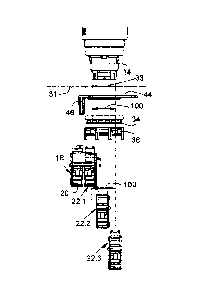
[0028] Fig. 1 shows the safety switch 10, which comprises a switch head 14
having
actuation means. The figure shows the head-fastening alternative of a switch
head. The
plunger (actuation means 12) can be seen in Fig. 4 from the underside thereof.
CA 02916124 2015-12-18
[0029] In the head fastening shown, the mounting adapter 36 is clipped onto
the switch
head on the exit side of the plunger. The mounting adapter 36 is directed
towards the
contact side of the individual switch blocks of the switch module and joins
the individual
switch blocks 22.1, 22.2, 22.3 together. The individual switch blocks ¨
including the
signalling switch block ¨ are inserted into the mounting adapter 36 and
likewise clipped in.
Therefore the switch module together with the signalling switch block is fixed
to the switch
head.
[0030] The switch head 14 is mounted in a round mounting opening 33 from the
inner side
of the housing wall 31 using a threaded ring 34. Mounting can also take place
in the upper
side, for example, of a cover-shaped housing (30', 30"). Fig. 4 and Fig. 5
show two
alternatives of a cover-shaped housing.
[0031] The longitudinal axis of the safety switch lies perpendicularly to the
plane of the
housing wall 31 or perpendicularly to the upper side of the housing. The
safety switch is
designed and installed such that the plunger, upon actuation (from the
inoperative position
into the switch position), actuates the contact elements of the switch module
18. The
essential function of the safety switch 10 consists in the fact that, upon
actuation (pushing in,
pressing in), it influences the contact elements of the switch module 18 in
such a way that an
OFF switch function and/or a warning function occurs. The safety switch is
most often used
for an emergency off function, and therefore the safety switch is also
referred to as an
EMERGENCY OFF button. The actuation of the safety switch can be associated
with a lock
in the switch position.
[0032] The present arrangement is, according to the invention, provided with a
monitoring
function. This function is effective if the switch module is separated from
the safety switch, in
particular if the switch head is separated from the switch module. The
monitoring function
should likewise be effective if individual switch blocks of the switch module
are separated or
incompletely installed. The separation can occur by destruction of the
construction or by
unauthorised access (tampering) or by incorrect assembly.
[0033] In Fig. 1, the switch module 18 comprises two individuals switch blocks
(22.1, 22.2).
The input terminals 25 of the individual switch blocks are at the front
(visible) and the output
terminals of the individual switch blocks are on the rear side and not
visible. The switch
module 18 is supplemented by a signalling switch block 20 in such a way that
the signalling
CA 02916124 2015-12-18
6
switch block is arranged in parallel with the individual switch blocks 22.1,
22.2 and has the
same orientation as the individual switch blocks. The signalling switch block
20 lies in a
laterally offset manner next to the individual switch blocks so that the
signalling contact 42 is
associated with the (rigidly arranged) actuation pin 46. The actuation element
of the
signalling contact is located outside the actuation range 100 of the plunger.
[0034] The rigid actuation pin 46 is located on a pin-retaining panel 44. The
pin-retaining
panel 44 is retained and fastened on the mounting opening by the threaded ring
34 together
with the switch head from the inner side. The actuation pin 46 protrudes
perpendicularly from
the pin-retaining panel, which bears against the housing wall 31 (cover 30').
Therefore, the
actuation pin 46 is in parallel with the axis of the plunger.
[0035] In the case of correct assembly of the switch module and the switch
head, the
actuation pin 46 acts upon the signalling contact of the signalling switch
block 20 so that the
signalling contact enters the closed position. In both the inoperative
position and the switch
position of the safety switch the signalling contact is closed, and the
signalling current path is
closed.
[0036] A preferred special embodiment as shown in Fig. 1 can consist in the
fact that the
signalling switch block 20 is designed as a double switch block. The double
switch block has
two spatially parallel contact elements which are bridged on the rear side of
the double
switch block. Therefore, the two contact elements of the double switch block
(20, 22.1) are
connected in series. The switch actuator of the signalling switch block 20 is
on the upper
side of the double switch block. The signalling switch block 20, which is on
the left-hand side
in Fig. 1, is acted upon by the actuation pin 46. The individual switch
blocks, which are on
the right-hand side in Fig. 1, are actuated by the plunger 12 of the switch
head in the switch
position. In the inoperative position of the switch head and in the case of
correct assembly,
the signalling contact is closed. The signalling contacts 42 of the signalling
current path are
visible schematically, having been printed on the signalling switch block 20.
[0037] Fig. 2 individually shows the pin-retaining panel 44 having an
actuation pin 46.
[0038] Another alternative of an embodiment of at least one actuation pin 46'
is described
below with reference to Fig. 4.
CA 02916124 2015-12-18
7
[0039] In Fig. 2, the actuation pin 46 is also shown to have a spacer 48. The
length of the
actuation pin 46 is selected such that, in the assembled state, the signalling
contact 42 is
actuated. In a further preferred embodiment, the actuation pin can be provided
with an
opening on the free front end. The opening 47 can be designed as an insertion
opening or
as a threaded hole, into which a spacer 48 can be inserted. The spacer can be
designed as
either a pin 48 or an adjusting screw. The spacer 48 can be used to adapt the
length of the
actuation pin 46, so that different distances from the switch head and from
the signalling
contact block can be bridged depending on the variants of the assembly.
Different distances
are present if the safety switch is installed in housings which have housing
walls (31) of
different thicknesses. Two limit pegs 49 are provided on the pin-retaining
panel 44 in parallel
with the actuation pin 46, as a result of which the position of the mounting
adapter 36
(described below) can be set easily.
[0040] Fig. 3 shows an exploded front view of the safety switch having a
switch head, switch
module and signalling switch block. As in Fig. 1, the same reference numerals
can be seen:
switch head 14 in the head-fastening alternative; housing wall 31; pin-
retaining panel 44
having an actuation pin 46; threaded ring 34; mounting adapter 36; individual
switch blocks
22.1, 22.2, 22.3; signalling switch block 20.
[0041] The actuation range 100 of the plunger of the safety switch is in
particular
emphasised. The plunger actuates only the contact elements of the switch
module 18 or the
contact elements of the individual switch blocks 22.1, 22.2 and 22.3.
[0042] The signalling switch block 20 (and its signalling contacts 42) are
located laterally
outside the actuation range 100 and are associated with the (rigidly arranged)
actuation pin
46.
[0043] What is not shown is a preferred special embodiment which can consist
in the fact
that the switch module is constructed only from individual switch blocks. That
is to say that
the signalling switch block is also incorporated as an individual switch block
in a
correspondingly enlarged mounting adapter 36.
[0044] If the switch module is separated from the safety switch, the actuation
pin 46 comes
out of engagement with the signalling contact of the signalling switch block.
The signalling
current path is opened, and therefore a warning or notification signal can be
emitted thereby.
CA 02916124 2015-12-18
8
In the switch position of the switch head and in the case of correct assembly,
the second
switch actuator of the signalling switch block is actuated together with the
individual switch
blocks. In the electrical circuit which is associated with the safety switch,
the signalling
current path, which is open in this case, can be "ignored" since the actuation
of the safety
switch itself causes the safety function to be triggered.
[0045] Fig. 4 shows a first cover 30' (housing cover) in which a switch head
14 is inserted
into the mounting opening. Fig. 4 shows the situation in exploded view in
conjunction with
the pin-retaining panel 44.
[0046] Fig. 5 shows a second cover 30" (housing cover) for receiving the
switch head 14.
This figure also shows the mounting opening 33 in the cover 30". On the inner
side of the
cover 30", two rigid actuation pins 46' are integrally formed with the cover.
This is a variant
having two actuation pins 46'. The actuation pins are formed so as to be
opposite on the
mounting opening 33. It makes no difference which position the cover 30"
assumes when
assembled with respect to a switch module. In every position of the cover, one
of the
actuation pins assumes the correct position in relation to the signalling
switch block. In
contrast with the embodiment of the pin-retaining panel 44 in Fig. 2, no
further individual part
on which an actuation pin is formed is required. The actuation pins 46' in the
cover 30" can
likewise be designed to have openings (47) and to have spacers (48) as in Fig.
2.
[0047] The invention can be summarised as follows:
[0048] A safety switch is proposed which has a switch head (comprising
actuation means
and a button top), the safety switch being mounted, using fastening means
(threaded ring),
in a housing wall in a mounting opening. The actuation means (plunger) is
designed and
installed such that, upon actuation into the switch position, it actuates
contact elements of a
switch module 18. A known problem in the case of safety switches is that
incorrect assembly
of the switch head and the switch module or unauthorised separation of the
switch head and
the switch module is not recognisable from the outside and the desired safety
shutdown
function does not occur. It is therefore provided that the switch module 18 is
extended by a
signalling switch block 20 which contains contact elements located in a
signalling current
path, the signalling switch block being acted upon by an actuation pin 46 that
is rigidly
arranged with respect thereto in the assembled state of the safety switch, and
therefore
when it is not in the assembled state or the assembled state is changed, the
actuation pin
CA 02916124 2015-12-18
9
comes out of engagement with the signalling switch block 20 and opens the
signalling
current path. The actuation element of the signalling contact and the
signalling switch block
are located outside the actuation range of the actuation means (plunger) of
the safety switch.
CA 02916124 2015-12-18
Reference numerals
10 pressure-actuatable safety switch
12 plunger (Fig. 4)
14 switch head (button)
18 switch module comprising at least one individual switch block
signalling switch block
22.1, 22.2, 22.3 individual switch blocks
input terminal (output terminal)
30', 30" two covers
31 housing wall
33 mounting opening in 30', 31
34 fastening means (threaded ring)
36 mounting adapter
42 monitoring contacts or signalling contacts
44 pin-retaining panel
46, 46' actuation pins
47 opening (insertion opening or threaded hole)
48 spacer as a pin or adjusting screw
49 limit peg