Note : Les descriptions sont présentées dans la langue officielle dans laquelle elles ont été soumises.
CA 02922548 2016-02-26
WO 2015/077806 PCT/'AT2014/000185
System for transporting people
The specific invention relates to a system for
transporting people or goods having at least one
transport cable to which a cable car vehicle which is
constructed with a travel mechanism and a vehicle cabin
can be coupled or having at least one carrier cable or
at least one travel path on which at least one cable
car vehicle which is constructed with a travel
mechanism and a vehicle cabin can be moved by means of
a traction cable to which the travel mechanism is
coupled.
Cable car systems are known for transporting people.
These are systems in which cable car vehicles, for
example, cable car cabins, are moved along at least one
carrier cable, wherein they are moved by means of a
traction cable or in which the cable car vehicles are
secured to a transport cable or can be coupled to a
transport cable.
These are also systems having cable car vehicles which
are moved along a fixed travel path, for example, along
travel rails, by means of traction cables.
In all such cable car systems, there is the difficulty
that the travel paths therefore have to be at least
substantially linear, since the guiding of the traction =
cables around curves involves significant technical
difficulties.
Cable car systems in which the cable car vehicles are
moved along carrier cables or by means of transport
cables are therefore advantageous since the carrier
cables or the transport cables are guided by means of
supports, whereby transport of people is enabled in a
1
CA 02922548 2016-02-26
WO 2015/077806
PCT/AT2014/000185
simple manner, even under difficult topographical
conditions.
Systems for transporting people using cable car
vehicles which are provided with a drive motor by means
of which they can be moved along travel paths, in
particular along travel rails, are therefore
advantageous since the travel paths may be constructed
with curves without technical difficulties being caused
thereby during the movement of the cable car vehicles.
An object of the specific invention is to provide a
system for transporting people by means of which, on
the one hand, the advantages of the known systems for
transporting people are ensured and, on the other hand,
the disadvantages thereof are avoided.
This is achieved according to the invention in that the
at least one transport cable or the at least one
carrier cable or the travel path is adjoined by at
least one additional travel path, in particular at
least one travel rail, along which at least one carrier
vehicle which is constructed with a drive motor for the
cable car vehicle can be moved, wherein the travel
mechanism of the cable car vehicle can be advanced
toward the carrier vehicle and can be secured thereto,
whereby the cable car vehicle can be moved by means of
the carrier vehicle along the at least one adjacent
travel path.
Preferably, the at least one adjacent travel path for
the carrier vehicle is formed by at least one travel
rail or at least one travel beam.
Furthermore, the carrier vehicle can be constructed
with at least two pairs of running rollers and where
applicable with pairs of guiding rollers.
2
CA 02922548 2016-02-26
WO 2015/077806
PCT/AT2014/000185
Preferably, the carrier vehicle is constructed with a
carrier frame for the travel mechanism of the cable car
vehicle, to which carrier frame the travel mechanism of
the cable car vehicle can be locked. To this end, the
carrier vehicle and the cable car vehicle can be
constructed with at least one locking device for
securing the travel mechanism of the cable car vehicle
to the carrier vehicle.
Preferably, the locking device has two clamping jaws.
In this instance, a fixed and a movable clamping jaw
may be provided, wherein the movable clamping jaw can
be moved by means of a clamping lever counter to the
action of a restoring force, preferably of a pressure
spring, from the closed position into the open
position. In this instance, the clamping lever can be
constructed with a control roller with which a control
rail is associated in the transfer station.
Furthermore, the travel mechanism of the cable car
vehicle may be constructed with at least one locking
pin which cooperates with the clamping jaws located on
the carrier vehicle.
The carrier vehicle may be constructed with a
combustion engine or with an electric motor, wherein
the electric motor is supplied with electrical power by
means of conductor rails which are arranged along the
travel paths. In addition, the carrier vehicle may be
able to be driven in an inductive manner.
A system according to the invention for transporting
people is explained in greater detail below with
reference to an embodiment illustrated in the drawings,
in which:
3
CA 02922548 2016-02-26
WO 2015/077806
PCT/AT2014/000185
FIG 1, FIG. 1A are a side view and a plan view of a
portion of a system according to the invention for
transporting people with cable car vehicles,
respectively,
FIG. 2, FIG 2A are a side view and a plan view of a
transfer station which is located in such a system in a
state drawn to an enlarged scale with respect to FIG 1
or FIG. 1A, respectively,
FIG 3. shows the transfer station according to FIG. 2,
drawn to an enlarged scale in comparison therewith,
FIG. 3A shows the transfer station according to FIG. 3
in which a cable car vehicle and a carrier vehicle are
located,
FIG. 3B shows the transfer station according to FIG.
3A, wherein the travel mechanism of the cable car
vehicle is located on a carrier vehicle,
FIG. 3C shows the transfer station according to FIG.
3B, wherein the carrier vehicle with the cable car
vehicle has been moved away from the transfer station,
FIG. 4 is a front view of two travel paths on which a
cable car vehicle can be moved in each case by means of
carrier vehicles,
FIG 4A is a side view of one of the travel paths on
which a cable car vehicle can be moved by means of a
carrier vehicle,
FIG. 5 is a front view of the travel mechanism of a
cable car vehicle, which is located on a carrier
vehicle, drawn to an enlarged scale compared with FIG.
4 and FIG 4A, and
FIG 5A shows a detail of FIG 5, drawn to an enlarged
scale in comparison therewith.
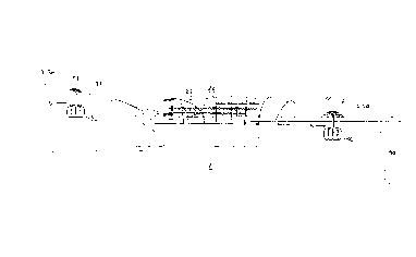
As can be seen from FIG. 1 and FIG. 1A, the illustrated
portion of such a system for transporting people has an
end station 1 and a transfer station 2. Between the end
station 1 and the transfer station 2 are two pairs of
4
CA 02922548 2016-02-26
WO 2015/077806
PCT/AT2014/000185
carrier cables 3, 3a which are carried by at least one
support 4. Cable car vehicles 5 which are coupled to
traction cables 31 and which are constructed with cable
car cabins can be moved along the carrier cables 3, 3a.
At the transfer station 2, the carrier cables 3, 3a are
adjoined by travel paths 6, 6a which are located on
supports 4a and along which carrier vehicles 7 which
are constructed with drive motors for the cable car
vehicles 5 can be moved. Since the carrier vehicles 7
are not moved by means of traction cables, but instead
by means of the drive motors which are located thereon,
the travel paths 6, 6a do not need to extend in a
linear manner. Instead, the travel paths 6, 6a may be
constructed with curves.
The travel paths 6, 6a may extend either as far as an
additional transfer station, which pairs of carrier
cables 3, 3a adjoin again, or as far as a second end
station. In this instance, any number of such portions
of pairs of carrier cables 3, 3a and travel paths 6, 6a
may be provided. The carrier cables 3, 3a are provided
in those portions in which the travel paths extend in a
linear manner. However, as soon as bends are required,
in particular as a result of the topographical
conditions in the route guiding, portions having curved
travel paths 6, 6a are provided.
The operation of such a system for transporting people
is as follows:
In the end station 1, the cabins of the cable car
vehicles 5 located therein are entered or left by
passengers. Subsequently, the cable car vehicles 5 are
moved by means of the traction cable 31 along the
carrier cables 3 to the transfer station 2. In the
transfer station 2, the cable car vehicles 5 are
5
CA 02922548 2016-02-26
WO 2015/077806
PCT/AT2014/000185
transferred onto a carrier vehicle 7 at that location.
Subsequently, this carrier vehicle 7 with the cable car
vehicle 5 which is secured thereto is moved along the
travel path 6 either to another transfer station or to
a second end station. From the second end station, the
cable car vehicles 5 are moved back along the travel
path 6a and the carrier cables 3a to the first end
station 1.
As can be seen from FIG. 2 and FIG. 2A, guiding rails
21 which are associated with the respective pairs of
the carrier cables 3, 3a and transport tires 22 which
are associated therewith are located in the transfer
station 2. The cable car vehicles 5 are constructed
with cable car cabins 50 and travel mechanisms 51. By
means of the transport tires 22, the travel mechanisms
51 of the cable car vehicles 5, after they have been
uncoupled from the traction cable 31, are moved further
along the guiding rails 21. The traction cable 31 is
laid over three redirection discs 32 by means of which
it is guided back parallel with the second carrier
cable 3a of the pair of carrier cables 3, 3a to the
first end station 1. The pairs of carrier cables 3, 3a
are adjoined by the travel paths 6, 6a which are each
formed by pairs of travel rails 61, 61a, along which
the carrier vehicles 7 and the cable car vehicles 5
which are carried thereby can be moved.
FIG. 3 shows a transfer station 2 in which a carrier
vehicle 7 is located.
FIG. 3A shows the transfer station 2, in which a cable
car vehicle 5 having a cabin 50 is located, after it
has been uncoupled from the traction cable 31, wherein
the travel mechanism 51 thereof is moved along one of
the guiding rails 21 by means of the transport tires 22
to the carrier vehicle 7.
6
CA 02922548 2016-02-26
WO 2015/077806
PCT/AT2014/000185
FIG. 3E shows the transfer station 2, wherein the cable
car vehicle 5 is located in the position after the
travel mechanism 51 thereof has been approached toward
the carrier vehicle 7, wherein it is locked thereto.
Subsequently, the drive of the carrier vehicle 7 is
switched on, whereby it is moved with the cable car
vehicle 5 along the travel rails 61, as illustrated in
FIG. 30.
In FIG. 4 and FIG. 4A, a portion of this cable car
system which is constructed with travel paths 6, 6a is
illustrated as a front view.
The travel paths 6a, 6a are located on carrier beams 41
of supports 4a.
Each of the travel paths 6, 6a has a pair of travel
rails 61, 61a along which the carrier vehicles 7 can be
moved. The travel mechanism 51 of a cable car vehicle 5
is located on the carrier vehicles 7. There is
articulated to the travel mechanism 51 a carrier bar 52
to which the cabin 50 is secured. The travel mechanisms
51 are constructed with four pairs of running wheels 53
which are supported on rockers 54.
With reference to FIG. 5 and FIG. 5a, the travel
mechanism 51 of the cable car vehicle 5 and the carrier
vehicle 7 and the locking of the travel mechanism 51 to
the carrier vehicle 7 are explained below.
There is articulated to the travel mechanism 51 the
carrier bar 52, to the lower end of which the cabin 50
- which is not illustrated in this drawing - is
secured. The travel mechanism 51 is constructed with
four pairs of running wheels 53, by means of which the
cable car vehicle 5 can be moved along the carrier
cables 3, 3a. The travel mechanism 51 is further
constructed with clamping jaws 55 by means of which the
travel mechanism 51 can be clamped to the traction
7
CA 02922548 2016-02-26
WO 2015/077806
PCT/AT2014/000185
cable 31 which is associated with the two pairs of
carrier cables 3, 3a. The two clamping jaws 55 are
moved into their closed position by means of control
rollers 56 which are under the action of pressure
springs 57, whereby the travel mechanism 51 can be
coupled to the traction cable 31.
The travel rails 61, 61a are secured by means of
carrier sheets 62 which are spaced apart from each
other to carrier pipes 63 which extend along the travel
paths 6, 6a. The carrier pipes 63 are secured to the
carrier beam 41. Each carrier vehicle 7 is constructed
with a travel frame 71 on which there are supported a
plurality of pairs of running rollers 72, guiding
rollers 73 which can be rotated about axes which are
orientated at least substantially horizontally, and
guiding rollers 74 which can be rotated about axes
which are orientated at least vertically.
The running rollers 72 travel on the upper side of the
travel rails 61, 61a. The guiding rollers 73 and 74
travel on horizontal and vertical abutment faces of the
travel rails 61, 61a, whereby the carrier vehicle 7 is
guided along the travel paths 6, 6a. Each carrier
vehicle 7 is constructed with a carrier frame 75, on
which the travel mechanism 51 of the cable car vehicle
5 is brought for support. The travel mechanism 51 is
secured to the carrier vehicle 7 by means of two
locking devices 8.
As can be seen in particular in FIG. SA, the locking
devices 8 comprise a fixed clamping jaw 81 and a
movable clamping jaw 82 which are located on the
carrier frame 75, and a locking pin 83 which is secured
to the travel frame 51 by means of a carrier sheet 87.
The movable clamping jaw 82 is located on a clamping
lever 84 which can be moved by means of a control
8
CA 02922548 2016-02-26
WO 2015/077806
PCT/AT2014/000185
roller 85 which is guided along a control rail 80
counter to the action of a pressure spring 86 into the
open position thereof and is retained therein.
As soon as the travel mechanism 51 on the carrier
vehicle 7 has been moved into position so that the
locking pin 83 is located between the two clamping jaws
81 and 82 which are located in the open position
thereof, the movable clamping jaw 81, as soon as the
control roller 85 has left the control rail 80, is
moved by the pressure spring 86 into the closed
position thereof, whereby the travel mechanism 51 is
locked to the carrier vehicle 7.
When a cable car vehicle 5 is moved into a transfer
station 2, the cable car vehicle 5 is uncoupled from
the traction cable 31 and the travel mechanism 51
thereof is moved along the guiding rails 21 by means of
the transport tires 22 to a carrier vehicle 7 which is
located in the transfer station 2 and placed thereon.
Subsequently, the cable car vehicle 5 is secured by
means of the two locking devices 8 to the carrier
vehicle 7. Subsequently, the cable car vehicle 5 is
moved by means of the carrier vehicle 7 along the pair
of travel rails 61 to a second end station or to
another transfer station. In the other transfer
station, the cable car vehicle 5 is unlocked from the
carrier vehicle 7, further moved by means of the
transport tires 22 along the guiding rails 21 to
another pair of carrier cables 3, coupled at that
location to another traction cable 31 and moved along
the carrier cables 3 to another station.
Along the travel rails 61a and the carrier cables 3a,
the carrier vehicles 7 and the cable car vehicles 5 are
moved back to the transfer station 2 and to the end
station 1.
9
CA 02922548 2016-02-26
WO 2015/077806
PCT/AT2014/000185
The drive of the carrier vehicles 7 is carried out by
means of combustion engines or by means of electric
motors. To this end, there may be provided along the
travel paths 6, 6a conductor rails by means of which
the electric motors are supplied with electrical power.
In addition, an inductive drive of the carrier vehicles
7 may be provided.
By means of such a combination of a system for
transporting people formed by carrier cables 3, 3a and
travel paths 6, 6a, the travel paths may therefore be
adapted to the specific topographical conditions since
the travel paths 6, 6a do not have to extend in a
linear manner, but instead can be constructed with
curved regions.