Note : Les descriptions sont présentées dans la langue officielle dans laquelle elles ont été soumises.
CA 02925784 2016-03-29
WO 2014/063040 PCT/US2013/065662
APPARATUSES AND METHODS FOR DISHWASHER RACK EMPTYING
[011 This application claims the benefit of United States Provisional Patent
Application Serial No. 61/715,744, filed on October 18, 2012, which
application is
incorporated by reference herein as though set forth herein in full.
FIELD OF THE INVENTION
[021 The present invention pertains, among other things, to apparatuses,
systems, methods and techniques for facilitating the emptying of a dishwasher
rack, and is
particularly applicable to commercial dishwasher racks.
BACKGROUND
1031 It is common in the restaurant, food service, and beverage industry to
use
automatic dishwashers that accept a standard dishwasher rack for cups and
glasses.
Generally speaking, a conventional dishwasher rack is in the shape of a
rectangular
(typically square) box with a bottom panel and four sidewalls, but an open
top. Within this
box is a rectangular grid of walls or slats, defining a matrix of compartments
into which
glasses or cups may be inserted, typically having paddle-shaped walls that
extend higher
in the center thereof than at the ends so as to protect glasses placed in the
compartments
and yet permit water to flow through a substantial portion of the dividers.
The grid
typically is molded so as to be integral with the sidewalls and includes a
multiplicity of
shapes and number of compartments and sizes to fit a wide variety of sizes of
glasses. For
example two common rack configurations contain four or five rows and columns
of
compartments (i.e., 4 x 4 or 5 x 5). The compartments of the adjacent rows and
columns
typically are nested with one another, so that adjacent compartments share a
wall.
1041 Different racks with different sized compartments commonly are used to
most closely match the diameter of the glasses or cups being washed. However,
a
conventional dishwasher rack typically is 19.72"x19.72" and is divided into 16
compartments (4 x 4), with each compartment able to hold a glass with a
diameter of 4.25
inches or less, or is divided into 25 compartments (5 x 5), with each
compartment able to
hold a glass with a diameter of 3.35 inches or less, e.g., as described in
U.S. Patents
2,741,392, 3,283,915, 3,442,397, 3,584,744, 3,009,579, 3,245,548, 3,482,707
and
4,621,739, as well as in U.S. Patent Application Publication No. 2002/0117461.
The
1
CA 02925784 2016-03-29
WO 2014/063040 PCT/US2013/065662
forgoing sizes given for the compartments in a dishwasher rack are just
examples of
commonly used configurations, it being understood that many compartments
having many
other configurations, in terms of number of compartments and sizes of
compartments, are
available and useful for washing cups and glasses.
1051 A conventional dishwasher rack can consist of a single component (which
can be referred to as a base component) having the foregoing configuration.
Alternatively,
one or more "rack extenders", e.g., as discussed and/or shown in U.S. Patents
D399,614,
D400,321 and in U.S. Patent Application Publication Nos. 2003/0178378 and
2002/0117461 can be attached to the base component to increase the height or
to change
the number, the size or the configuration of the interior compartments of the
rack, and
thereby accommodate taller glasses or cups or such different sizes or
configurations.
These one or more extenders are stacked one on top of the base component and
then on
top of each other, with all the components typically fitting together and
being held in place
by a number of interlocking pins and receiving sockets, e.g., as described
and/or shown in
U.S. Patents 3,283,915, 3,584,744, D399,614 and D400,321, as well as in U.S.
Patent
Application Publication Nos. 2002/0117461 and 2003/0178378. A rack extender
typically is similar to the base unit in cross-section, having the same (or
roughly the same)
length and width and a matching internal grid, but has both an open bottom and
an open
top. Such dishwasher racks provide for easy transport of cups and glasses and
work well
in many cases.
SUMMARY OF THE INVENTION
[061 However, the present inventor has discovered that problems arise in
connection with these conventional structures, particularly when high volumes
of cups
and/or glasses are required for service in a busy restaurant, bar, event or
other venue. In
this case, service staff spends a significant amount of time unloading
dishwasher racks of
cups and glasses. To empty a conventional dishwasher rack of its contents,
each cup or
glass typically must be lifted out of its compartment by hand. The time spent
emptying
cups and glasses from a dishwasher rack becomes significant when many cups or
glasses
are needed and multiple racks must be emptied.
[07i In addition to the time spent emptying commercial dishwasher racks by
hand, one glass at a time, this method of emptying the rack sometimes is not
sanitary
because each clean glass mush be touched by hand in order to remove the glass
from the
2
CA 02925784 2016-03-29
WO 2014/063040 PCT/US2013/065662
dish rack, and when working in a commercial kitchen a worker's hands can
become easily
soiled or otherwise exposed to non-sanitary surfaces.
[081 In one respect, the present invention addresses these problems by
providing
a dishwasher rack that has a configurable or releasable surface (which can be
either or
both of its top surface and/or its bottom surface), that can be configured to
hold glasses,
cups or other beverage containers within, and that when the rack is in a
position in which
the configurable surface is facing and immediately adjacent to (e.g., within a
short
distance from) a second surface (such as a countertop, tabletop or a tray),
the configurable
surface can be easily changed to release the cups, glasses and/or other
beverage containers
so that they fall (usually a very short distance, e.g., less than 1-2 inches)
to the second
surface. After that, the rack can be lifted up, leaving the beverage
containers on the
second surface.
[091 According to one particular aspect, the present invention provides for a
mechanism to hold and/or lock beverage containers securely into a dishwasher
rack,
thereby enabling the dishwasher rack to be inverted (turned upside down) while
keeping
the beverage containers securely held within the dishwasher rack. With the
dishwasher
rack inverted (upside down) the dishwasher rack is placed on any desired
(e.g., flat)
surface (e.g., a tray, countertop or tabletop), and then the securing
mechanism is released,
causing the beverage containers within the dishwasher rack to drop out of the
rack onto the
desired surface. The release of beverage containers from the dishwasher rack,
as
described above, allows the empty dishwasher rack to be lifted away from the
flat surface,
leaving the beverage containers behind on the selected surface (e.g., without
leaving
behind any portion of the dishwashing apparatus).
1101 According to another aspect, the invention provides for a similarly
releasable mechanism to be installed in (or as) the floor (or bottom surface)
of the
dishwasher rack. Such a structure allows beverage containers to be loaded into
the rack
through the top openings of the rack compartments (in the same manner as a
conventional
dishwasher rack is loaded) but, unlike conventional racks, this rack can be
emptied all at
once by releasing the cups, glasses and/or other beverage containers through
the floor (or
bottom) of the dishwasher rack, without inverting the rack (and, again,
without manually
removing each one from its separate compartment).
1111 Still further, both of the foregoing mechanisms (for locking or securing
the
contents of the dishwasher rack into the rack and for releasing the contents
of the
dishwasher rack through the top and/or bottom surface of the rack), or aspects
of them,
3
CA 02925784 2016-03-29
WO 2014/063040 PCT/US2013/065662
may be incorporated together in the same rack. A dishwasher rack having a
combination
of these structures (i.e., securing and releasing capabilities in both the top
and the bottom
surfaces of the rack) is desirable when cups, glasses and/or other beverage
containers are
being transported or for any other reason when it is advantageous to secure or
lock them
into the rack and, at the same time, to have an ability to empty the rack
relatively easily
and, in some cases, without inverting it.
[121 The described systems, methods and apparatuses that use a releasable
mechanism to lock cups, glasses and/or other beverage containers into a
dishwasher rack
so that the rack can be inverted and then the contents released onto a
different surface
and/or use a releasable mechanism that allows the contents of the dishwasher
rack to be
removed all at once through the floor or bottom of the rack permit a much
quicker method
of emptying a dishwasher rack than is currently available. Additionally, the
described
systems facilitate the emptying of a commercial dishwasher rack of glasses
without the
need to touch each glass by hand, thereby reducing the risk of unsanitary
hands coming
into contact with a drinking glass during the process of removing the cups,
glasses and/or
other beverage containers from the dishwasher rack.
[131 Thus, one embodiment of the invention is directed to a dishwasher rack
that
includes: an interior structure divided into separate compartments, each sized
and
configured to hold an individual beverage container; a top side through which
the
compartments may be loaded; a bottom side having a support surface; and a
release
mechanism. The top and/or bottom side has a configurable surface that provides
a closed
configuration in which it is capable of supporting beverage containers and an
open
configuration in which beverage containers are able to pass through. When the
dishwasher rack is placed on top of a desired exterior surface with the
configurable surface
immediately adjacent to the exterior surface, the release mechanism can be
operated to
change the configurable surface from the closed configuration to the open
configuration,
causing any enclosed beverage containers to drop down onto the exterior
surface and
remain there when the dishwasher rack is lifted up and away.
[141 The foregoing summary is intended merely to provide a brief description
of
certain aspects of the invention. A more complete understanding of the
invention can be
obtained by referring to the claims and the following detailed description of
the preferred
embodiments in connection with the accompanying figures.
4
CA 02925784 2016-03-29
WO 2014/063040 PCT/US2013/065662
BRIEF DESCRIPTION OF THE DRAWINGS
[151 In the following disclosure, the invention is described with reference to
the
attached drawings. However, it should be understood that the drawings merely
depict
certain representative and/or exemplary embodiments and features of the
present invention
and are not intended to limit the scope of the invention in any manner. The
following is a
brief description of each of the attached drawings.
[161 FIG. 1-A is a perspective view of a rack extender having a configurable
surface on its top side, configured in the closed position; FIG. 1-B is a
perspective view of
the rack extender with its configurable surface changed to the closed
position; FIG. 1-C
illustrates a sectional view of a portion of the front edge of the rack
extender; FIG. 1-D is a
perspective exploded view of a rack that includes a base component and the
extender
component; and FIG. 1-E is a perspective exploded view of a rack that includes
an
alternate base component and the extender component.
[171 FIG. 2 is a perspective view of a dishwasher rack having a removable
panel.
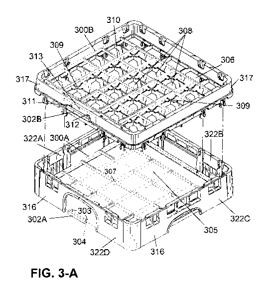
[181 FIG. 3-A is an exploded view of a dishwasher rack having movable grids in
its base portion and in its extender portion, both in the closed positions;
FIG. 3-B is an
exploded view of the dishwasher rack having its movable grids in the open
positions; FIG.
3-C is a sectional view of a portion of the dishwasher rack; and FIG. 3-D is a
perspective
view of a portion of the dishwasher rack.
1191 FIG. 4 is an exploded view of a dishwasher rack having two movable grids
in its base portion.
[201 FIG. 5 is a perspective view of a dishwasher rack having separate
rotating
tines.
[211 FIG. 6 is a perspective view of a dishwasher rack having a rotating grid.
1221 FIGS. 7-A and 7-B are perspective views of a dishwasher rack extender
having rotating dividing supports.
[231 FIG. 8 is a perspective view of a dishwasher rack having flaps that fold
or
rotate up and down.
1241 FIG. 9 is an exploded view of a dishwasher rack having two movable sets
of parallel rods in its rack extender.
[251 FIGS. 10A&B are exploded views of a dishwasher rack having two
movable sets of parallel rods in its base component.
CA 02925784 2016-03-29
WO 2014/063040 PCT/US2013/065662
DESCRIPTION OF CERTAIN REPRESENTATIVE EMBODIMENTS
[261 As discussed in greater detail below, an apparatus according to the
present
invention can encompass: (i) an entire dishwasher rack, (ii) a "rack
extender", and/or (iii)
one or more components that can be used with either. A rack extender 12
according to the
present invention is illustrated in FIGS. 1-A, 1-B and 1-C, while dishwasher
racks 16 and
46 which include extender 12 are illustrated in FIGS. 1-D and 1-E.
[271 The initial embodiment of the present invention concerns a modified rack
extender 12 and the use thereof in a dishwasher rack 16. In this embodiment,
rack
extender 12 is simply placed on top of the rest of dishwasher rack 16, in the
same manner
as a conventional rack extender.
[281 As shown in FIGS. 1-A and 1-B, rack extender 12 is of conventional
construction except for: (i) the inclusion of and ability to accommodate
parallel rods 10;
and (ii) a mechanism 13 to move the rods between the open position (shown in
FIG. 1-A)
and the closed position (shown in FIG. 1-B). More specifically, rack extender
12
preferably has a conventional frame 22 made of four side walls 22A-D, which
typically
are arranged in a substantially square or rectangular shape, e.g., usually
with the standard
dimensions noted above. Within frame 22 is a conventional open grid 17 that
separates
the individual beverage containers (e.g., cups, mugs and/or glasses). As with
conventional
rack extenders, rack extender 12 has an open bottom surface, but instead of
having a
perpetually open top surface, the top surface of rack extender 12 is
adjustable and can be
configured to be open or closed. In the present embodiment, this adjustability
is
accomplished through the use of a set of movable parallel rods 10.
[291 Referring to FIG. 1-C, in the present embodiment each of parallel rods 10
is
fitted with a bushing 20 and is secured by threads 18 and a c-pin 19 to a
carrier 60 that is
disposed between the inside wall 15 and the outside wall 11 (which together
make up the
front wall 22A) of the rack extender 12. Also attached to carrier 60 is a
sliding tab, grip,
handle or other element (referred to as a "tab" herein) 13 that is exposed
through a slot 21
in the outside wall 11 of the front wall 22A. A similar or identical carrier
60 preferably
also is provided within the wall 22C that is directly opposite and parallel to
wall 22A, and
a tab 13 also can be provided in the wall 22C. In alternate embodiments, a
single tab 13 is
provided just in the front wall 22A or just in the rear wall 22C that is
directly opposite and
parallel to wall 22A. In the present embodiment, these tab(s) 13 terminate
just inside the
6
CA 02925784 2016-03-29
WO 2014/063040 PCT/US2013/065662
outer surface of outside wall 11 (as shown in FIG. 1-C) or at most is/are
flush with such
outer surface.
[301 When sliding tab 13 is in the open position shown in FIG. 1-A, the
parallel
rods 10 extend through slots 14 in the inner side wall 15 of front and rear
structural side
walls 22A&C and align exactly with the grid 17 of the dishwasher rack
compartments,
with one additional rod 10 disposed within a groove in the right side wall
22D. When the
sliding tab 13 is then moved by a user into the closed position (as shown in
Fig 1-B), the
carrier 60 also is moved, which in turn also moves the attached parallel rods
10 out of
alignment with the compartment grid 17 and into a position approximately
halfway
between the parallel slats of grid 17 that extend perpendicular to the carrier
60. The result
is to effectively obstruct the openings to all the compartments and thereby
lock or secure
the beverage containers into their respective compartments. A latching or
locking
mechanism preferably is used with the sliding tab 13, the carrier 60 or rods
10 to prevent
the rods 10 from changing position accidentally. This latching or locking
mechanism can
be (or include), e.g., a pin, a snap-fit connection, a flexible and resilient
lip engaging with
another lip, an engagement slot (e.g., in slot 21) at each end of the range of
travel of tab
13, or any other known temporary locking or securing mechanism.
1311 Referring to FIG. 1-D, in the present embodiment the base of the
dish rack
16 is a conventional rack commonly used in the industry, having sidewalls 22,
but unlike
extender 12 alone, rack 16 (or the base portion of it) includes a sturdy
bottom surface or
rack floor 50, typically with openings that are sufficiently small to prevent
the beverage
containers from falling through while still allowing water to flow through
during the
washing process. In the present embodiment, the top rack extender is extender
12, and
any number of conventional extenders may be used between rack 16 and extender
12 to
increase the height of the dishwasher rack according to a desired function.
[321 The present invention can involve racks having any number, any size
and/or any shape of compartments. In the embodiment described above, the
inventive
features are provided in the rack extender 12 portion of the dishwasher rack
16.
1331 Preferably, any dish rack or rack extender in accordance with the
invention
is made primarily of molded plastic. For example, a polypropylene copolymer is
a
suitable material for the rack and extender. However, the rods 10 and carrier
60, as well
as related components, can be made of other materials, such as plastic, metal
and/or
natural or synthetic rubber. Although rods 10 are referenced above, it should
be noted that
any kind of elongated members, having a rectangular, square or any cross-
sectional shape,
7
CA 02925784 2016-03-29
WO 2014/063040 PCT/US2013/065662
may be used instead of rods. Also, such elongated members 10, together with
the carriers
60, may be formed in any other way, such as by molding or otherwise forming
all of such
components together as a unitary piece.
[341 In accordance with the present method for using rack 16: sliding tab 13
is
moved to the open position and latched or locked into place while the rack is
empty of
beverage containers, rack 16 is loaded with beverage containers while sliding
tab 13 is in
the open position; with the rack full of beverage containers sliding tab 13 is
then moved to
the closed position and locked or latched into place and placed into the
automatic
dishwasher; the dishwasher is started; upon completion, rack 16 is removed
from the
dishwasher and flipped over onto a desired surface; sliding tab 13 is unlocked
and moved
to the open position, causing the beverage containers to drop slightly down
onto that
surface; rack 16 is lifted up, leaving the beverage containers behind; and
finally rack 16 is
flipped over again and the foregoing process is repeated.
1351 In the commercial food and beverage service industry it is common to
place
clean cups, glasses and/or other beverage containers containers on rubber
drying mats. In
accordance with the above mentioned process for use of a dishwasher rack 16,
which
includes a mechanism for quickly emptying the rack, it is recommended that, to
prevent
breakage of beverage containers, rack 16 be placed on to a rubber drying matt
before
operating tab 13 to empty the rack 16 of the beverage containers.
[361 The following is a detailed description and method for use of an
alternate
embodiment of the invention described above in connection with FIGS 1-A, 1-B
and 1-C.
[371 Referring to FIG 1-E, in the present embodiment a structure similar to
that
provided in rack extender 12 and shown in FIGS 1-A and 1-B is provided in the
base
component of a rack, e.g., rack base 46. Here, rather than having a fixed
bottom surface or
floor, the base component includes a set of parallel elongated members 40 that
cover and
obstruct the areas directly beneath the lower openings of the compartments
formed by grid
17 of the upper rack extender 12 when in the closed position, thereby
substantially
forming the floor of the rack 46, such that any glasses or other beverage
containers placed
into the rack will be resting on and be suspended within the rack 46 by the
parallel
members 40. The parallel members 40 are connected through slots, or channels
44 located
in the inner side walls 42B and 42D of rack 46. The set of parallel members 40
are
connected to a carrier mechanism similar or identical to that described above
and
illustrated in FIG 1-C which lies between the inner and outer sidewalls of the
rack 46 and
is attached to sliding tabs 43 accessible on the outer side of walls 42D and
42B. Sliding
8
CA 02925784 2016-03-29
WO 2014/063040 PCT/US2013/065662
tabs 43 are designed to allow for the control and operation of the elongated
members 40
from outside of the rack 46. Directly below the elongated members 40 is a
support grid 41
having the same dimensions and configuration as that of grid 17 in the above
rack
extender 12 and aligning exactly with the grid 17 of the rack extender 12.
Grid 41 is made
integral with the walls of rack 46 and is designed to strengthen rack 46 and
provide
additional support for the parallel members 40.
[381 In accordance with the present method for using rack 46 (i.e., the base
component with extender 12 attached): sliding tabs 43 are moved to the closed
position
and latched or locked into place while the rack is empty of glasses; sliding
tabs 13 are
moved to the open position moving the set of elongated members 10 into
alignment with
the dividers 17 of the extender 12, thereby opening the tops of the
compartments of
extender 12 and allowing beverage containers to be loaded into the rack 46;
rack 46 is then
loaded with beverage containers; and sliding tabs 13 are moved to the closed
position,
locking and securing the glasses into the rack such that the beverage
containers will not
fall out of the rack even when the rack is turned upside down or inverted
(e.g., thereby
allowing for storage and/or safe transport of a rack 46 full of beverage
containers). Once
filled with beverage containers, rack 46 is placed into the automatic
dishwasher; the
dishwasher is started; upon completion, rack 46 is removed from the dishwasher
placed
onto a desired surface; sliding tabs 43 are unlocked and moved to the open
position,
causing the beverage containers to drop slightly down our of the bottom of
rack 46 onto
that surface; rack 46 is lifted up, leaving the beverage containers behind;
and the foregoing
process is repeated.
1391 FIG. 2 illustrates a rack 116 in the inverted (or upside down)
position,
according to an alternate embodiment of the present invention. Rack 116
preferably is
similar to a conventional dishwasher rack (e.g., using any of the same general
structure,
dimensions and/or materials mentioned above), but instead of having a fixed,
closed,
integral bottom, rack 116 instead can be configured so as to be open at its
bottom 118 as
well as at its top 119. More specifically, rack 116 includes a removable
bottom panel 120
that forms the floor of rack 116 when the panel 120 is inserted into the lower
receiving slot
125 near the bottom edge of the front wall 122A, slid all the way in until it
reaches the rear
wall 122B and, preferably, then locked or otherwise secured in place, e.g., by
using a
simple latch, one or more clips, a snap-fit connection, a flexible and
resilient lip engaging
another lip, a slot-and-tab locking mechanism (e.g., rotating the tab into the
slot), and/or
any other mechanism. Although the removable panel 120 is shown as a solid
piece, in
9
CA 02925784 2016-03-29
WO 2014/063040 PCT/US2013/065662
reality it often will have a number of small openings (for example, configured
as a mesh or
molded plastic with circular holes) that allow water to freely flow through
the panel. In
the present embodiments, rack 116 includes grooves or channels 113 on the
inside of right
sidewall 122C and left side wall 122D for guiding and then helping to support
panel 120,
and also includes a groove 113 in rear wall 122B for accepting and then
helping to support
panel 120. In addition, the distal end of removable panel 120 and the groove
113 in rear
wall 122B may be sized and shaped to form a snap fit, thereby providing at
least one
securing mechanism to hold panel 120 in place. Alternatively, rear wall 122B
may be
provided with one or more flexible and resilient clips for the same purpose.
The support
grid 110 located just below receiving slot 125 adds structural support to the
rack 116 and
to the removable floor panel 120 and preferably aligns exactly with the
internal
compartment grid of the rack. In the current embodiment, the structure for
accommodating removable floor panel 120 is provided in the base component of
rack 116,
and any number of conventional extenders can be attached on top of this base
component.
As with rack 16, a polypropylene copolymer is a suitable material for the rack
116 and any
extender.
[401 In accordance with the present method for using rack 116: beverage
containers are loaded into rack 116 with panel 120 fully inserted through
receiving slot
125 and with rack 116 in the upright position (i.e., inverted from the view
shown in FIG.
2); the dishwasher is started; upon completion, rack 116 is removed from the
dishwasher
and placed onto a desired surface; panel 120 is removed from slot 125 (e.g.,
by pulling on
handle 128 [label in drawing] after releasing any separate securing mechanism,
either or
both functioning as a release mechanism), causing the beverage containers to
drop slightly
down onto that surface; rack 116 is lifted up, leaving the beverage containers
behind; and
finally panel 120 is again fully inserted into receiving slot 125, the
foregoing process can
then be repeated as often as desired. As will be readily appreciated, as with
the structure of
rack 46, the structure of rack 116 eliminates two flips of the rack and,
therefore, is often
easier to use.
[411 However, it should be noted that in alternate embodiments a similar (or
identical) removable panel and similar (or identical) corresponding receiving
structure
instead (or in addition) are provided at the top surface of a rack according
to the present
invention. Also, in certain embodiments of the present invention, the top and
bottom of
the rack are identical to each other, so the designations "top" and "bottom"
are just
arbitrarily assigned. Still further, in alternate embodiments the structure
for
CA 02925784 2016-03-29
WO 2014/063040 PCT/US2013/065662
accommodating a removable panel 120 is provided in a rack extender, in
addition to or
instead of or in the base component of the rack.
[421 A still further embodiment is now discussed in reference to FIGS. 3-A, 3-
B,
3-C and 3-D. FIGS. 3-A and 3-B illustrate rack 316, which preferably is
similar to rack 16
(e.g., using any of the same general structure, dimensions and/or materials
mentioned
above and having any of the features and variations described above). However,
unlike
rack 16, which has a closed, integral bottom, rack 316 instead is configured
to be open at
its bottom 305 as well as at its top 306. A sturdy but movable grid 307 forms
the very
bottom or floor of rack 316. More specifically, movable grid 307 is not
integral with walls
322A ¨ 322D of rack 316, but instead has one or more components that extend
into
channels 300A in the inner walls 322A, 322B, 322D (but not in wall 322B). In
the present
embodiment, movable grid 307 has the same dimensions as the dividing grid 309
that
forms the compartments 308 of rack extender 317. When handle 302A is in the
closed
position movable grid 307 crosses and thereby obstructs the lower openings of
the
compartments 308 formed by grid 309 such that any beverage containers placed
into rack
316 (i.e., compartments 308) will be supported and rest securely on movable
grid 307.
Channels 300A allow the movable grid 307 to slide laterally toward and away
from walls
322B and 322D inside of rack 316, e.g., by operating handle 302A that is
attached to grid
317 by carriers 304, which in turn pass through slots 303 in side wall 322D of
rack 316,
thereby operatively connecting handle 302A to movable grid 307. As a result of
this
configuration, sliding movable grid 307 a one-half width within the structure
of rack 316
switches between the open and closed positions. In the present embodiment, a
sturdy
movable grid 310 that is similar or identical to grid 307 (preferably having
at least
approximately the same dimensions) is built into the top most portion of rack
extender
317. Movable grid 310 is attached to handle 302B by carriers 311 that pass
through slots
312 in wall 313. Movable grid 310 has the same dimensions as the dividing grid
309 that
forms the compartments 308 of rack extender 317. When handle 302B is in the
closed
position, movable grid 310 crosses and thereby obstructs the upper openings of
the
compartments 308 formed by grid 309 such that any beverage containers in the
rack 316
(i.e., in compartments 308) after the closing of grid 310 will be held
securely within rack
316 by the grids 307 below and 310 above, such that the beverage containers
may not be
released from the rack 316 until one of the movable grids is moved from the
closed
position to the open position. This allows for rack 316, when filled with
beverage
containers and with movable grids 307 and 310 in the closed and locked
positions, to be
11
CA 02925784 2016-03-29
WO 2014/063040 PCT/US2013/065662
turned at any angle, even inverted, without having any beverage containers
fall out of the
rack 316.
[431 Referring to FIGS. 3-C and 3-D, the structure of handle 302A is shown
most clearly in FIG. 3-C, which depicts a sectional side view of a portion of
dishwasher
rack 316, including a sliding grid 307 attached by carriers 304 to handle
302A. The
exterior structure of handle 302A is handle housing 330, and handle 302A is
attached to
the sliding grid 307 at points on the interior of the handle 302A with a
suitable standard
fastener, such as a pan head screw 331A, and is affixed so the head of the
fastener 331A is
flush and flat, not protruding into the open space between the handle housing
330 and the
plunger 333 such that it may obstruct the movement of plunger 333. Any
reasonable
number of fasteners 331A may be used to affix and hold the handle housing 330
firmly to
sliding grid 307. The handle housing 330 is fitted with a button or plunger
333. The
plunger 333 is held in place by its shape, having flanges 334 that fit into
the handle
housing and are secured into place by the hanger flanges 335 in the inside
walls of the
handle housing 330. Above the plunger 333 a coil spring 336 is fitted in the
open space
between the handle housing 330 and the plunger 333. A flat iron latch 337 is
attached to
the plunger 333 and secured by a fastener such as a pan head screw 331B. One
end of a
flat iron latch 337 is fitted into a groove or channel 338 in the sliding grid
307, and the
opposite end of the flat iron latch 337 is secured by a fastener such as a pan
head screw
331B to the plunger 333 inside the handle housing 330 and laying between the
handle
housing 330 and below the coil spring 336. The flat iron latch 337 runs
through an
opening 339 in the side of the handle housing 330. There is a space or window
or gap 340
in the sliding grid 307 where the handle housing 330 affixes to the sliding
grid 307. This
gap 340 allows the flat iron latch 337 to be mounted within the thickness of
the sliding
grid 307 without inhibiting the movement of the sliding grid 307. The stopper
or catch
341 of the flat iron latch is of an appropriate length so that when the
sliding grid 307 is in
the closed position, as in FIGS. 3-B and 3-C, the catch 341 is positioned just
to the inside
of the interior surface of wall 322D.
[441 Preferably, any dish rack or rack extender in accordance with the
invention
is made primarily of molded plastic. For example, a polypropylene copolymer is
a
suitable material for the rack and extender. However, the sliding grid 307 and
handle
302A, as well as related components, can be made of other materials, such as
plastic,
metal and/or natural or synthetic rubber. Although sliding grid 307 is
referenced above, it
should be noted that any kind of grid, having a rectangular, square or any
cross-sectional
12
CA 02925784 2016-03-29
WO 2014/063040 PCT/US2013/065662
shape, may be used instead. Also, such grid 307, together with the handle
302A, may be
formed in any other way, such as by molding or otherwise forming all of such
components
together as a unitary piece.
[451 Referring to FIG. 3-A illustrating rack 316 in the closed position and
FIG.
3-B illustrating rack 316 in the open position: in accordance with the present
method for
using rack 316: in order to load beverage containers into rack 316 (i.e.,
compartments 308)
handle 302B is placed in the open position (illustrated in FIG 3-B) thus
perfectly aligning
grid 310 with compartment grid 309 and leaving the tops of compartments 308
unobstructed by any of the members of grid 310. Also before loading beverage
containers
into rack 316 handle 302A is moved into the closed and locked position
(illustrated in FIG
3-A) so that the carriers 304 attached to the handle 302A move base component
grid 307
horizontally so that grid 307 is out of alignment with the compartment grids
309 and is
covering the lower openings of compartments 308 of the above rack extender 317
thus
creating the sturdy floor of the rack 316. When all compartments 308 have been
filled
with beverage containers handle 302b is then moved to the closed position
(illustrated in
FIG 3-A), thereby locking and securing the beverage containers into the rack
316 such that
the beverage containers will not fall out of the rack 316 even when the rack
316 is turned
upside down or inverted, and thus allowing for storage or safe transport of a
rack 316 full
of beverage containers; with both handles of rack 316 in the closed and locked
position the
filled rack 316 is placed into the automatic dishwasher and the dishwasher is
started; upon
completion, rack 316 is removed from the dishwasher and placed onto a desired
surface;
handle 302, still being in the closed position, is now firmly grasped so that
the plunger 333
is pressed fully up, compressing the coil spring 336 and lifting the end of
the flat iron latch
337 so that the catch 341 is moved into parallel alignment with the sliding
grid 307,
thereby freeing the latch 337 and catch 341 to pass through the gap 342 in the
sidewall
322D of the rack 316 without inhibiting or impeding or otherwise coming into
contact
with the inner side wall 322D of the rack 316; then, with handle 302 firmly
grasped as
described above, the handle 302 is pulled outwardly and away from the wall
322D of the
rack 316, causing the sliding grid 307 to slide from the closed position to
the open position
(shown in FIG. 3-B), shifting the base component grid 307 into perfect
alignment with the
above rack extender grid 309 and allowing the beverage containers held within
the
compartments 308 of the extender 317 and previously resting on the sliding
grid 307 to
drop slightly onto the adjacent surface; the entire rack 316 (including
extender 317) is then
lifted vertically away from such adjacent surface, leaving the beverage
containers behind
13
CA 02925784 2016-03-29
WO 2014/063040 PCT/US2013/065662
resting on such surface; and finally, handle 302 is pushed back into the
closed and locked
position, and the foregoing process is repeated.
[461 It is common in the industry to place clean beverage containers such as
beverage containers on rubber mats for drying before use. In accordance with
the above-
mentioned process for use of a dishwasher rack 316, which includes a mechanism
for
quickly emptying the rack, it is preferred that, to prevent breakage of
beverage containers,
the rack 316 be placed onto a rubber drying mat before emptying the rack of
glasses or
other beverage containers.
1471 FIG. 4 illustrates a rack 416 according to another embodiment of the
present invention. Rack 416 preferably is similar to rack 316 (e.g., using any
of the same
general structure, dimensions and/or materials mentioned above and having any
of the
features and variations described above). For instance, like rack 316 the
floor of rack 416
is not fixed or integral with rack 416. Differing from rack 316, the floor of
rack 416 is
comprised of two sliding grids 401 and 402, with one slightly above the other.
Both grids
401 and 402 and are independent and not directly connected to one another.
Grid 401 is
attached to a handle 403B and grid 402 is attached to handle 403A, handle 403B
being on
the opposite side of rack 416 from handle 403A and on the outer side of wall
422B of rack
416.
[481 The present method for the operation of rack 416 (containing two sliding
grids) is identical to the method for operating rack 316 with one main
difference; after the
dishwasher cycle has been completed and rack 416 is removed and placed onto a
desired
surface; both lower handles 403A and 403B are firmly grasped, lifting the
plunger 333,
engaging the flat iron latch 337 and disengaging the catch 341; both handles
403A and
403B are then pulled in opposing directions and away from the rack 416 causing
the
independently sliding grids 401 & 402 to move into alignment with one another
and to
align perfectly with the above matrix of the dividers 409 of the rack extender
417 so that
no members of grids 403A or 402B are covering any lower openings to
compartments
408, thereby allowing the beverage containers contained within the
compartments 408 of
rack 416 to drop slightly through the bottom of the rack 416 onto the adjacent
surface.
Alternate Configurations
1491 In the embodiments described above, three approaches have been described
for selectively controlling whether a top or bottom surface of a dishwasher
rack is
sufficiently open to allow the beverage containers to pass through ¨ a
slidable set of
14
CA 02925784 2016-03-29
WO 2014/063040
PCT/US2013/065662
parallel bars, a removable panel, and a slidable grid or set of grids. As
indicated above, in
certain embodiments another important consideration is that this
controllability is capable
of being exercised when the subject surface is adjacent and very close to a
second surface
(e.g., no more than 1-2 inches away), so that the beverage containers can drop
down onto
the second surface. The section below describes a number of other structures
for
selectively opening and closing the top or bottom surface of a dishwasher rack
in
accordance with these features.
[501 1. FIG. 5: Tines 501 built into the top of the sidewalls 502 of
each
compartment 508, held by a center shaft 503 and having gears connected to the
shaft and
to a drive system of jointed shaft are made to pivot (i.e., rotate) toward the
center of each
compartment opening 508 to obstruct the opening of each compartment 508
securely
holding the contents of each compartment 508 into the dishwasher rack.
[511 2. FIG. 6: The topmost part 603 of the grid 607 that creates the
compartments 608 is a separate section and not made integral with grid 607 or
the walls
622A or 622B or 622C or 622D of rack 616. This top and rotatable grid 603 is
attached to
the rack 616 by a center shaft 604 that runs through the height of the rack
616 from top to
bottom. The topmost section of the rotatable grid 603 is fixed to the shaft
604 and can be
rotated by hand by grasping the grid 603 and rotating it manually, or grid 603
may be
rotated by turning a knob that lays flush with the bottom surface of the base
of rack 616
and therefore may be accessed when rack 616 is inverted. When in the open
position, grid
603 is rotated on the center shaft 604 such that grid 603 aligns perfectly
with the divider
grid 607, allowing beverage containers to be loaded into the rack compartments
608. In
the closed position the rotating grid 603 is rotated out of alignment with the
lower divider
grid 607, e.g., by 1/8 turn in a clockwise direction (as depicted in FIG. 6).
The
misalignment of the rotatable grid 603 completely obstructs the compartment
608
openings, locking or securing the contents of each compartment 608 into the
rack 616.
1521 When using rack 616, rotatable grid 603 is first rotated into the open
position so that the compartment 608 openings are not obstructed; beverage
containers are
loaded into the compartments 608 of rack 616; when rack 616 is full, grid 603
is rotated
into the closed position; rack 616 is then placed into an automatic dishwasher
and the
wash cycle is imitated; when washing is complete, rack 616 is removed from the
dishwasher, inverted or turned upside down, and then placed onto a desired
(e.g., flat)
surface; in the upside down position, the beverage containers within rack 616
are resting
on and held into rack 616 by the rotatable grid 603; with rack 616 resting on
the flat
CA 02925784 2016-03-29
WO 2014/063040 PCT/US2013/065662
surface the knob that is flush on the bottom of rack 616 and is attached to
the center shaft
604 that attaches to the rotatable grid 603 is then turned, in turn moving the
rotatable grid
603 into the open position and bringing the grid 603 into perfect alignment
with grid 607;
this movement of the rotatable grid 603 into the open position allows the
beverage
containers that were resting on the rotatable grid 603 to drop out of rack 616
and fall
slightly coming to rest on the flat surface; then rack 616 is lifted
vertically away from the
flat surface leaving behind the beverage containers
1531 3. FIG. 7-A and FIG. 7-B: A dishwasher rack extender 712 is fitted with
parallel dividing supports 717, which are mounted to a gear mechanism built in
the walls
of the rack 722C and 722D. The gear assembly is attached to a sliding switch
713,
exposed by slot 721, that when activated will engage the gears and rotate the
gears in turn
rotating the dividing supports 717. Two of the dividing supports 717A and 717B
are built
into the walls 722A and 722B, respectively, of the rack extender 712, so that
in the open
position each such support is vertically aligned with its corresponding inner
wall 722A or
722B of the rack extender 712 and lay flush and slightly within its
corresponding wall
722A or 722B. In the open position, the dividing supports 717 of the rack
extender 712
align vertically, as in FIG 7-B, allowing cups, glasses or other beverage
containers to be
loaded into the rack. In the closed position, the parallel dividing supports
717 have rotated
to a horizontal position, as show in FIG 7-A, effectively obstructing the
openings of the
compartments of the rack and locking the contents of the rack into the rack.
[541 4. FIG. 8: The compartment dividers 807 are provided with flaps 804 on
all four sides of each compartment 808. These flaps 804 are made to move on
hinges 803
by the activation of an array of gears and rods connected by universal joints.
When in the
closed position, the flaps 804 hinge from the base of each flap and are folded
inwardly
toward the center of the compartment 808, thereby covering the opening to the
compartment 808 from four sides, obstructing the compartment opening 808, and
holding
the contents of the compartments into the dishwasher rack 816.
1551 5. FIG. 9: A grid is formed by two sets of parallel rods 901 & 902 (or
other
elongated members) in the top of the extender 917 of the dishwasher rack 916
above the
divider elements 907 and above the top of the openings (or compartments) 908
of the grid
of the elements 907. Each set of parallel members 901, 902 is made to slide
independently
and in the opposite direction of the other set of parallel members along slots
911 in the
sidewalls 922A & 922B of the rack 916 and is attached to an independent
carrier, such as
carrier 60 shown in FIG 1-C, that is secured to and operated by a sliding tab
913. In the
16
CA 02925784 2016-03-29
WO 2014/063040 PCT/US2013/065662
closed position, the parallel members 901 & 902 obstruct each compartment
openings 908
at an even interval across all compartments. In the open position the parallel
members 901
& 902 slide one group 901 toward the second group 902 and come into alignment
together
with the compartment grid 907 of the uppermost dishwasher rack extender 917.
In the
open position the parallel rods 901 & 902 are not obstructing any compartment
openings
908 of the dishwasher rack extender 917 allowing any beverage container to
pass freely
out of the top of the dishwasher rack 916 unobstructed.
[561 6. A grid is formed by two intersecting sets of parallel members. Each
parallel set slides independently of the other set of parallel members. In the
closed
position the crossing members intersect in the center of each compartment of
the
dishwasher rack, fully obstructing the compartment and locking or securing the
contents of
the compartment into the dishwasher rack. In the open position the crossing
members
intersect in alignment with the grid that makes up the compartments of the
dishwasher
rack. The alignment of the crossing members matches exactly with the alignment
of the
compartments, allowing a beverage container placed into the compartment of the
dishwasher.
[571 7. FIGS. 10A & 10B: similar to rack 46 but having one additional set of
movable parallel members; A strong floor is formed in the base component of
rack 1016
by two movable sets of parallel members 1001 & 1002. The members 1001 and 1002
align across the lower openings of the compartments 1010 that are formed by
the
compartment grid 1009 and obstruct the lower openings of the compartments 1010
such
that any beverage container placed into any one of the rack compartments 1010
will come
to rest and be supported by members 1001 and 1002. The supporting grid is in
exact (or at
least close) alignment with and has the exact (or at least approximately the
same)
dimensions as the grid that defines the compartments 1010 of the dish rack
extender 1017
above. Each parallel set of members (e.g., 1001) is made to slide
independently and in the
opposite direction of the other set of parallel members (e.g., 1002) and is
moved by
operation of handle 1020 which engages an array of gears within the walls
1022D and
1022B of rack 1016, moving carriers that attach to the movable members through
slots
1004 in the lower parts of inner walls 1022D and 1022B of rack 1016. In the
closed
position, represented in FIG 10A, the parallel members 1001 and 1002 obstruct
each
compartment opening 1010 at an even interval across all compartments 1010 of
the rack
extender 1017. In the closed position, any beverage containers contained
within
compartments 1010 of the rack 1016 will rest on two of the evenly spaced
parallel
17
CA 02925784 2016-03-29
WO 2014/063040 PCT/US2013/065662
members 1001 & 1002. When the handle 1020 is operated and moved into the open
position, as show in FIG 10B, the parallel members 1001 & 1002 slide toward
one another
to come into alignment with the grid 1009 that makes up the compartments 1010
of the
dishwasher rack extender 1017. In the open position the crossing members 1001
& 1002
are not obstructing any compartments 1010 of the dishwasher rack extender 1017
and
allow any beverage containers to pass completely through the rack freely.
Representative Control Mechanisms
[581 Any of the mechanisms described herein for selectively securing beverage
containers into a dishwasher rack may be used in any combination with any of
the devices
described herein for controlling such selectivity, such as any of the
following:
[59i 1. A lever built into the outer wall of the dishwasher rack is
pulled or
pushed, engaging an array of gears or rods causing the mechanism to move into
the open
or closed position or causing a motor or servo or actuator to be engaged to
move the
mechanism from the open to the closed position and from the closed to the open
position.
[601 2. A sliding latch between the inner and outer wall of the dishwasher
rack
is slid to the open or to the closed position, engaging a carrying device, a
gear array, or
push rods to open or close the compartments in the dishwasher rack.
1611 3. A knob is rotated engaging a gear array, or turning a shaft to open or
close the compartments in the dishwasher rack.
[621 4. A button or switch built into the outer wall of the dishwasher rack is
pushed, engaging a motor, servo or actuator that engages a gear array, or
turns a shaft to
open or close the compartments in the dishwasher rack.
1631 5. A panel is pulled out of or pushed into a receiving slot by hand to
uncover or cover dishwasher rack compartments.
Additional Considerations.
[641 Some of the above embodiments employ mechanisms and configurable
surfaces used to secure beverage containers into dishwasher rack by covering
the top of
the dishwasher rack compartments to allow the rack to be inverted without
having the
contents of the rack fall out of the compartments of the dishwasher rack, and
then to
release the beverage containers when the rack is completely inverted and in
the desired
position.
18
CA 02925784 2016-03-29
WO 2014/063040 PCT/US2013/065662
[651 Other embodiments employ mechanisms and configurable surfaces in the
floor of the dishwasher rack so that beverage containers loaded into the rack
compartments
rest on the configurable surface in its closed position in the usual way as
when using a
conventional dishwasher rack commonly found in the industry. When the
configurable
surface in the floor of the rack is then opened, the beverage containers in
the rack are
allowed to pass through the bottom of the rack, allowing the rack to be
quickly emptied
from a standard upright position.
[661 In still further embodiments, any of such mechanisms and configurable
surfaces used to cover the compartments of the dishwasher rack are provided in
both the
top and the bottom of the rack and/or selectively used in either the top or
the bottom of the
rack. In certain embodiments, the two mechanisms will work in unison to allow
the
contents of the rack to be locked and held into the compartments of the rack,
while
allowing for the release of the contents of the compartments of the rack
through the floor
of the rack while the rack is in the upright position.
[671 In certain cases it is advantageous to provide a configurable
(e.g.,
releasable) surface in a dishwasher rack extender only. Automatic dishwasher
rack
extenders are commonly used in the industry to increase the wall height of
dishwasher
racks by stacking multiple extenders together. A dishwasher rack extender
having a
configurable top surface according to the present invention allows the use and
corresponding advantages of the present invention with dishwasher racks that
are currently
in use, e.g., by simply attaching such a rack extender to a conventional
dishwasher rack.
[681 All of the stated variations of the invention for securing beverage
containers into a dishwasher rack preferably are used with a latch, lock or
other securing
device so the mechanism may be locked in the closed position. Such a securing
device
prevents the weight of the beverage containers and/or the movement of the full
rack by
being carried from causing the mechanism to open unintentionally (e.g.,
without being
operated by user).
1691 In the above disclosure, the invention is described with reference to the
attached drawings. However, it should be understood that the drawings merely
depict
certain representative and/or exemplary embodiments and features of the
present invention
and are not intended to limit the scope of the invention in any manner.
IN Any of the configurable surfaces and other mechanisms described
herein
may be used in the base component or in the rack extender portion of a rack.
Any
descriptions of a particular mechanism being incorporated into one such
component
19
CA 02925784 2016-03-29
WO 2014/063040 PCT/US2013/065662
should be understood as being merely exemplary. Also, although the present
disclosure
largely pertains to dishwasher racks having compartments for holding beverage
containers,
the configurable surfaces and other mechanisms of the present invention can be
incorporated into embodiments of dishwasher racks that are configured for
washing any
other type of container, plate, utensil or other article, and such racks often
will have
separate compartments, slots or other structures for holding the individual
articles and/or
for holding multiple similar articles. The types of configurable surfaces that
are preferable
for each such embodiment often will depend upon the shapes and/or sizes of any
such
compartments, slots or other structures and/or upon the shapes and/or sizes of
any items
included within the rack. For example, where a slot is used to accommodate a
plate, there
often will be a preference toward using movable rods or other elongated
members that are
oriented perpendicular to such slots.
1711 Many different embodiments of the present invention are described above,
with each such embodiment described as including certain features pertaining
to a
commercial dishwasher rack. However, it is intended that the embodiments of
the
invention described herein not be confined only to use in conjunction with
dishwasher
racks, but any embodiment of the invention, including any mechanism or method
for use,
may be used in conjunction with any other box, bin, rack or other container
for storage or
transportation having walls and a floor, whether or not including separate
compartments
and irrespective of the size(s) and/or shape(s) of any such compartments. Any
such
container in accordance with the present invention preferably includes at
least one
configurable surface (e.g., having any of these structures described above) as
its top and/or
bottom surface.
[721 In the event of any conflict or inconsistency between the disclosure
explicitly set forth herein or in the attached drawings, on the one hand, and
any materials
incorporated by reference herein, on the other, the present disclosure shall
take
precedence. In the event of any conflict or inconsistency between the
disclosures of any
applications or patents incorporated by reference herein, the more recently
filed disclosure
shall take precedence.
[731 In the above discussion, certain methods are explained by breaking them
down into steps listed in a particular order. However, it should be noted that
in each such
case, except to the extent clearly indicated to the contrary or mandated by
practical
considerations (such as where the results from one step are necessary to
perform another),
CA 02925784 2016-03-29
WO 2014/063040 PCT/US2013/065662
the indicated order is not critical but, instead, that the described steps can
be reordered
and/or two or more of such steps can be performed concurrently.
[741 Similarly, in the discussion above, functionality sometimes is
ascribed to a
particular module or component. However, functionality generally may be
redistributed as
desired among any different modules or components, in some cases completely
obviating
the need for a particular component or module and/or requiring the addition of
new
components or modules. The precise distribution of functionality preferably is
made
according to known engineering tradeoffs, with reference to the specific
embodiment of
the invention, as will be understood by those skilled in the art.
[751 In the discussions above, the words "include", "includes", "including",
and
all other forms of the word should not be understood as limiting, but rather
any specific
items following such words should be understood as being merely exemplary.
[761 Several different embodiments of the present invention are described
above, with each such embodiment described as including certain features.
However, it is
intended that the features described in connection with the discussion of any
single
embodiment are not limited to that embodiment but may be included and/or
arranged in
various combinations in any of the other embodiments as well, as will be
understood by
those skilled in the art.
[771 Thus, although the present invention has been described in detail with
regard to the exemplary embodiments thereof and accompanying drawings, it
should be
apparent to those skilled in the art that various adaptations and
modifications of the
present invention may be accomplished without departing from the spirit and
the scope of
the invention. Accordingly, the invention is not limited to the precise
embodiments shown
in the drawings and described above. Rather, it is intended that all such
variations not
departing from the spirit of the invention are to be considered as within the
scope thereof
as limited solely by the claims appended hereto.
21