Note : Les descriptions sont présentées dans la langue officielle dans laquelle elles ont été soumises.
CA 02926671 2016-04-08
1
PACKAGE FOR A SURGICAL MESH
The present invention relates generally to a package for a surgical mesh.
Background of the related art
Surgical meshes used for wall reinforcement, for example for the abdominal
wall,
are widely used in surgery. These surgical meshes are intended to treat, for
example, hernias by
temporarily or permanently filling a tissue defect. These surgical meshes are
made generally from
a surgical biocompatible textile and can have a number of shapes, for example
rectangular,
circular or oval, depending on the anatomical structure to which they are to
adapt. The surgical
mesh is generally flat and may vary in dimensions, from for example 5 X 10 cm
up to 30 X 50 cm,
depending on the size of the defect to be treated.
Before being packaged as a commercial product and shipped to hospitals or end-
users, the surgical mesh has to be sterilized to prevent contamination to the
patient body in
which it is intended to be implanted.
Gas sterilization is commonly used in the medical field and surgical meshes
are
usually sterilized by means of ethylene oxide (Et0) gas.
The sterilization process generally requires the immersion of the surgical
mesh in
ethylene oxide for a time sufficient for the gas to sterilize the surgical
mesh. For handling
purposes, the surgical mesh is usually inserted into a handling pouch before
being submitted to
the sterilization process.
The handling pouch is provided with a window made of a material which is
impervious to contamination by microorganisms, bacteria and/or a biologically
active substance
which may come into contact with the pouch while it is being handled, while at
the same time
remaining permeable to a sterilization gas such as for example ethylene oxide.
Such a material is
for example a nonwoven made of filaments of a high density polyethylene bound
together by
heat and pressure, such as a product sold by the Du Pont de Nemours under the
trademark
"Tyvek". The surgical mesh to be sterilized is therefore humidified by
exposure to water vapor,
inserted into a "Tyvek " pouch and submitted to ethylene oxide gas for
sterilization.
However, it may happen, in particular for large surgical meshes, that the
ethylene
oxide gas may not reach the entire surface of the surgical mesh and/or does
not diffuse in the
surgical mesh a sufficiently efficient manner when the surgical mesh is first
packaged in a pouch
with a "Tyvek " window. This proves to be a problem as it is desirable that
sterilization is
completed to a high degree on the entire surface of the surgical mesh.
CA 02926671 2016-04-08
2
Furthermore, in order to proceed to ethylene oxide sterilization, the
surgical mesh must be previously humidified. The larger the mesh, the more
humid
the mesh will be after the sterilization step. In addition, because of its
intrinsic nature,
the surgical mesh is subject to moisturization. Moisturization has to be
avoided during
transportation and storage so as to maintain optimal dry conditions of the
surgical
mesh at the moment of its use.
Summary of the invention
In this technical context, it would be desirable to provide a packaging for
a surgical mesh allowing an efficient ethylene oxide gas sterilization of all
surgical
meshes, whatever their size, that would prevent humidity of ambient air to
permeate
through the packaging, and that would also favour drying of the surgical mesh
during
storage and transportation.
The present invention relates to a package for a surgical mesh comprising
a receiving member configured and dimensioned to receive a surgical
mesh, and
a covering member configured and dimensioned to cover the said at least
one surgical mesh maintaining with the receiving member the surgical mesh in a
substantially flat position, and
a gas channelling network interposed between the said receiving
member and the said covering member configured to channel a sterilization gas
within the surgical mesh.
Thus, the invention makes it possible to maintain a surgical mesh in a
substantially flat position and to bring a sterilizing gas in the entire
surface of the
mesh. This proves to be a great advantage for large surgical meshes, which
tend to be
partially sterilised using prior art sterilizing techniques.
In a embodiment of the invention, the receiving member and the
covering member define at least one gas diffusing compartment connected to the
said
gas channelling network.
In an embodiment of the invention, the covering member includes at
least one cut off portion allowing a large exposure to a sterilizing gas and a
large
exposure for humidity absorption by a desiccant agent.
In an embodiment, the receiving member comprises a resting rib and an
inner wall configured to receive the at least one surgical mesh and the
covering
member comprises at least one resting rib and an inner wall configured to
maintain
CA 02926671 2016-04-08
,
3
the at least one surgical mesh between the said resting ribs and to define the
at least
one gas diffusing compartment for a sterilizing gas.
In an embodiment, the receiving member comprises at least one groove
and the covering member comprises at least one groove defining with at least
one
groove of the receiving member a channel for a sterilizing gas.
In an embodiment, the receiving member and/or the covering member
comprise at least one transverse resting ribs forming at least two diffusing
compartments.
In an embodiment, the receiving member and the covering member
include peripheral rim provided with at least one locking pin and at least one
corresponding locking opening.
In an embodiment, the peripheral rim includes a series of locking
tooth ing.
In an embodiment, at least one of the receiving member and of the
covering member includes a cavity configured to receive a capsule of desiccant
material.
In an embodiment, the receiving member and the covering member have
a substantially rectangular shape.
In an embodiment, the covering member includes at least two cut off
portions.
In an embodiment, the covering member includes a central portion and
two lateral portions extending from the central portion.
In an embodiment, the covering member includes a hinge allowing access
to the surgical mesh.
In an embodiment, the hinge is formed by a weakened line.
In an embodiment, the hinge is positioned at the junction the central
portion and the lateral portion.
Brief description of the drawings
The foregoing objects and advantages of the present invention will
become apparent from the reading of the following description in connection
with the
accompanying drawings, in which:
Fig. 1 includes a perspective view of a package according to an
embodiment of the invention;
CA 02926671 2016-04-08
4
Fig. 2 includes a perspective view of a receiving member of the
embodiment of Fig. 1;
Fig.3 includes a perspective view a the receiving member with a surgical
mesh;
Fig. 4 and 5 include perspective views of a covering member;
Fig. 6 includes an exploded view of another embodiment of the
invention.
Detailed description
Reference will now be made to the drawings wherein like structures are
provided with like reference designations.
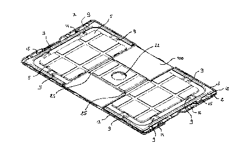
Turning to Fig. 1, a package 1 for a substantially rectangular mesh is
shown in an perspective view.
Package 1 includes a receiving member 2 and a covering member 3. In
the illustrated embodiment of Fig.1, the package 1 is shown as rectangular;
however,
the package 1 may be of any suitable shape for receiving a surgical mesh.
The surgical mesh 100 can be seen in Figs. 1 or 3.
The receiving member 2 has a generally planar shape. In the illustrated
embodiment, the receiving member 2 comprises a series of resting ribs 4
protruding
from an inner panel 5.
As depicted on Fig. 2, the receiving member 2 is thus provided with
transverse ribs 4 and longitudinal ribs 4 which divide the inner panel 5 into
diffusing
compartments 8 as will be explained later.
In the embodiment of Figs. 1 and 2, the receiving member 2 is provided
with four transverse resting ribs 4 and two longitudinal resting ribs 4, which
define
three diffusing compartments 8.
The resting ribs 4 include at least one groove 9. In the embodiment of
Figs. 1 to 3, the resting ribs 4 are provided with a series of grooves 9
spaced out at
regular intervals.
In embodiments, the inner wall 5 can be provided with strengthening
ribs 11.
The receiving member 2 further includes a peripheral rim 12.
Along each length of the receiving member 2, the peripheral rim 12
includes a series of locking toothing 13.
CA 02926671 2016-04-08
Along each width of the receiving member 2, the peripheral rim 12 is
provided with a locking pin 14 and a locking opening 15. The peripheral rim 12
can
also include one or more grooves 16.
Turning to Figs. 4 and 5, a covering member 3 is shown.
5 The covering member 3 has a generally planar shape. The covering
member 3 has a substantially planar shape and is comprised of a central
portion 20
and of two lateral portions 30 extending from the central portion 20 forming
substantially a H. As can be seen on Fig. 4, the covering member 3 includes
two
symmetrical cut off portions 40.
In the illustrated embodiment, the covering member 3 comprises a series
of resting ribs 4 protruding from an inner panel 5.
As depicted on Fig. 5, the covering member 3 is thus provided with
transverse ribs 4 and longitudinal ribs 4, which define with the inner panel 5
diffusing
compartments 8.
In the embodiment of Figs. 4 and 5, the covering member 3 is provided
with two transverse resting ribs 4 and two longitudinal resting ribs 4, which
define a
diffusing compartment 8 in each lateral portion 30.
The resting ribs 4 include at least one groove 9. In the embodiment of
Figs. 4 and 5, the resting ribs 4 are provided with a series of grooves 9
spaced out at
regular intervals.
In embodiments, the inner wall 5 can be provided with strengthening
ribs 11.
The covering member 3 further includes a peripheral rim 12.
Along each length of the covering member 3, the peripheral rim 12
includes a series of locking toothing 13.
Along each width of the receiving member 3, the peripheral rim 12 is
provided with a locking pin 14 and a locking opening 15. The peripheral rim 12
can
also include one or more grooves 16.
The central portion 20 can include a cavity 22 provided with three
retaining tabs 23.
In an embodiment, the covering member 3 includes two weakened
line 25 to form a hinge at the junction of the central portion 20 with each of
the
lateral portions 30.
The surgical mesh 100 is placed onto the receiving member 2 as can be
seen on Fig.3. The surgical mesh 100 seats on the resting ribs 4 and is
surrounded by
the peripheral rib 12.
CA 02926671 2016-04-08
6
The covering member 3 is placed above the receiving member 4 and is
locked onto the receiving member 2. The locking pins 14 of the covering member
3
are engaged into the corresponding openings 15 of the receiving member 2. The
locking toothing 13 of the receiving member 2 engage into the locking toothing
of the
covering member 3.
The surgical mesh 100 is thus interposed between the receiving
member 2 and the covering member 3 and is maintained in a substantially flat
position. The surgical mesh 100 is maintained between the resting ribs 4 of
the
receiving member 2 and the resting ribs 4 of the covering member 3.
It can be noted that, within the package 1, the gap between the resting
ribs 4 of the receiving member 2 and the resting ribs 4 of the covering member
3 can
be in the area of 1 mm while the surgical mesh 100 thickness can be in the
area of 0.6
mm.
When positioned in the package 1, the surgical mesh 100 is thus
maintained along the resting ribs 4; the part of the surgical mesh 100 which
is not
directly interposed between the resting ribs 4 of the receiving member 2 and
of the
covering member is received in the diffusing compartments 8 where the surgical
mesh
100 is free from contact with the package.
The surgical mesh 100 positioned in the package 1 may then be sterilized
by immersion in a sterilizing solution of gas including ethylene oxide.
The sterilizing gas can flow within the package 1 and diffuses into the
surgical mesh 100 through the cut off portion 40 and through the grooves 9
provided
in the resting ribs 4. The entire surface of the surgical mesh 100 is thus
exposed to the
sterilizing gas.
After sterilization, the package 1 can be hermetically sealed in a suitable
envelope like container (not shown) to be stored for a later use.
The central cavity 22 can receive a capsule of a desiccant material to
ensure that the any moisture within the surgical mesh 100 is captured. The
desiccant
capsule is maintained in position by the tabs 23. The cut off portions 40
provide a
significant exposure to the action of the desiccant capsule.
It can be appreciated that the receiving portion 2 and the covering
member 3 are devoid of sharp angles or sharp edges thus limiting the risk of
damaging
the container.
When needed on an operating room, the package 1 can be presented to
the medical staff.
CA 02926671 2016-04-08
7
One of the lateral portions 30 of the covering member 3 may be lifted
and may be folded along the weakened line 25 thereby giving access to the
surgical
mesh 100.
Figs. 6 depicts another embodiment of the invention.
In this embodiment of the invention, the receiving member 2 and the
covering member3 are identical.
A surgical mesh 100 is positioned onto a receiving member 2 such as the
receiving member 2 illustrated on Fig. 2 and a covering member 3. The covering
member 3 is structurally identical to the receiving member 2. However, the
covering
member 3 further includes a cavity 22 for a desiccant capsule.
The package described herein may be made of any material suitable for
sterilization such as plastic, foils, combination thereof and laminates
thereof and may
be formed using any suitable molding process.