Sélection de la langue

Search

Sommaire du brevet 2931229 

Énoncé de désistement de responsabilité concernant l'information provenant de tiers

Une partie des informations de ce site Web a été fournie par des sources externes. Le gouvernement du Canada n'assume aucune responsabilité concernant la précision, l'actualité ou la fiabilité des informations fournies par les sources externes. Les utilisateurs qui désirent employer cette information devraient consulter directement la source des informations. Le contenu fourni par les sources externes n'est pas assujetti aux exigences sur les langues officielles, la protection des renseignements personnels et l'accessibilité.

Disponibilité de l'Abrégé et des Revendications

L'apparition de différences dans le texte et l'image des Revendications et de l'Abrégé dépend du moment auquel le document est publié. Les textes des Revendications et de l'Abrégé sont affichés :

  • lorsque la demande peut être examinée par le public;
  • lorsque le brevet est émis (délivrance).
(12) Demande de brevet: (11) CA 2931229
(54) Titre français: CHAISE FLEXIBLE
(54) Titre anglais: FLEXIBLE CHAIR
Statut: Réputée abandonnée et au-delà du délai pour le rétablissement - en attente de la réponse à l’avis de communication rejetée
Données bibliographiques
(51) Classification internationale des brevets (CIB):
  • A47C 07/14 (2006.01)
  • A47C 05/12 (2006.01)
  • A47C 07/16 (2006.01)
  • A47C 07/44 (2006.01)
  • A47C 07/46 (2006.01)
(72) Inventeurs :
  • PIRETTI, ALESSANDRO (Italie)
(73) Titulaires :
  • PRO-CORD S.P.A.
(71) Demandeurs :
  • PRO-CORD S.P.A. (Italie)
(74) Agent: MACRAE & CO.
(74) Co-agent:
(45) Délivré:
(22) Date de dépôt: 2016-05-26
(41) Mise à la disponibilité du public: 2016-12-11
Licence disponible: S.O.
Cédé au domaine public: S.O.
(25) Langue des documents déposés: Anglais

Traité de coopération en matière de brevets (PCT): Non

(30) Données de priorité de la demande:
Numéro de la demande Pays / territoire Date
102015000022850 (Italie) 2015-06-11

Abrégés

Abrégé anglais


A chair comprising:
- a support structure (12) including a rigid front
fixing element (22), and
- an essentially L-shaped seating element (14),
including a seat portion (30) and a backrest portion (32)
connected to each other via an arcuate connecting portion
(34),
wherein the seat portion (30) comprises a front fixing
section (30a) fixed to said rigid front fixing element (22),
a main seat section (30c) having a concave cross-section and
a planar bending section (30b) located between said front
fixing section (30a) and said main seat section (30c) and
having a flat cross-section.

Revendications

Note : Les revendications sont présentées dans la langue officielle dans laquelle elles ont été soumises.


CLAIMS
1. A chair comprising:
- a support structure including a rigid front fixing
element, and
- an essentially L-shaped seating element, including a
seat portion and a backrest portion connected to each other
via an arcuate connecting portion having an upper portion
integral with a lower portion of the backrest portion and a
lower portion integral with a rear portion of the seat
portion,
wherein the seat portion comprises a front fixing
section fixed to said rigid fixing element, a main seat
section having a concave cross-section and a planar bending
section located between said front fixing section and said
main seat section and having a flat cross-section.
2. A chair according to claim 1, wherein said arcuate
connecting portion has a flat cross-section.
3. A chair according to claim 1, wherein said backrest
portion has a concave cross-section.
4. A chair according to claim 1, wherein said rigid
front fixing element comprises a hub, at least one arm that
projects upwardly from said hub and a fixing plate located at
an outer end of said at least one arm, wherein said front
fixing section of the seat portion is fixed to said fixing
plate.
5. A chair according to claim 4, wherein said planar
bending section of the seat portion is vertically spaced
apart from said rigid front fixing element.
- 7 -

Description

Note : Les descriptions sont présentées dans la langue officielle dans laquelle elles ont été soumises.

CA 02931229 2016-05-26
,
FLEXIBLE CHAIR
TEXT OF THE DESCRIPTION
Field of the invention
The present invention relates to a chair comprising a
support structure and a flexible seating element capable of
deforming elastically backwards under the user's weight.
Description of the prior art
In the state of the art, chairs equipped with an
elastically deformable backrest capable of assuming a rest
position and a backwardly inclined position are very
widespread. Simpler chairs have the seat fixed and the
backrest elastically inclinable backwards. Chairs are also
known, typically office chairs, provided with mechanisms that
synchronize the tilting movement of the seat and the backrest
to generate the required comfort. Chairs of this type offer a
high comfort due to the synchronized movement of the seat and
of the backrest, but have the drawback of a greater
complexity due to the mechanism that synchronizes the
movements of the seat and the backrest.
Object and summary of the invention
The present invention aims to provide a chair devoid of
mechanisms and that offers characteristics of comfort
comparable to those of traditional chairs with synchronized
seat and backrest.
According to the present invention, this object is
achieved by a chair having the characteristics forming the
subject of claim 1.
The claims form an integral part of the disclosure
provided here in relation to the invention.
- 1 -

CA 02931229 2016-05-26
Brief description of the drawings
The present invention will now be described in detail
with reference to the attached drawings, given purely by way
of non-limiting example, wherein:
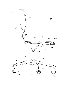
- Figure 1 is a perspective view of a chair according to
the present invention,
- Figure 2 is a perspective view of the part indicated
by the arrow II in Figure 1,
- Figure 3 is a side view of the chair of Figure 1,
- Figures 4, 5, 6, 7 and 8 are sections according to the
lines IV-IV, V-V, VI-VI, VII-VII and VIII-VIII of Figure 3,
respectively, and
- Figure 9 is a side view illustrating the chair of
Figure 1 in a rest position and in a backwardly inclined
position.
Detailed description
With reference to the figures, numeral 10 designates a
chair according to the present invention. The chair 10
comprises a base structure 12 and a seating element 14 fixed
to the base structure 12. In the illustrated example, the
base structure 12 comprises a central column 16 rotatable
about a vertical axis, carried by a plurality of arms 18
equipped at their ends with pivoting wheels 20. A base
structure of this type is not, however, mandatory and can be
replaced by base structures of different kinds depending on
requirements. For example, the chair according to the present
invention can be provided with a base structure with four
legs or with a cantilever frame.
A rigid fixing element 22 is fixed to the upper end of
the rotatable column 16. The rigid fixing element 22 is
- 2 -

CA 02931229 2016-05-26
preferably made of metal, for example, a light die-cast
alloy, and comprises - in one piece - a hub 24 fixed to the
central column 16, two arms 26 that extend in a cantilevered
manner from the hub 24 in a generally V-shaped configuration
and a front plate 28, which joins together the outer ends of
the arms 26. Alternatively, the rigid fixing element 22 can
have a single arm 26, in a central position with respect to
the front plate 28 according to a general T-shaped
configuration. The front plate 28 is spaced apart in the
horizontal direction with respect to the vertical axis of the
rotatable column 16. With reference to Figures 3 and 9, the
arms 26 extend upwardly starting from the hub 24, so that the
front plate 28 is located at a greater height with respect to
the upper end of the central column 16.
The seating element 14 is essentially L-shaped and is
preferably formed of a single piece of injection-molded
plastic material. Preferably, the seating element 14 is made
of compact polyurethane. This material has different
mechanical characteristics from the plastic materials
commonly used in the sector of chairs and, in particular,
proves very effective for designing elements with cross-
sections of reduced dimensions, but with high rigidity and
excellent elastic memory. The seating element 14 may be
produced using other plastic materials with good elastic
memory, such as, for example, nylon or the like.
The seating element 14 comprises a seat portion 30 and a
backrest portion 32, connected together by an arcuate
connecting portion 34. The arcuate connecting portion 34 has
an upper portion integral with a lower portion of the
backrest portion 32 and a lower portion integral with a rear
- 3 -

CA 02931229 2016-05-26
portion of the seat portion 30.
The seat portion 30 is, in turn, subdivided into three
sections: a front fixing section 30a, a planar bending
section 30b and a main section 30c. The front fixing section
30a rests on the upper surface of the front wall 28 of the
rigid fixing element 22 and is fixed to the rigid fixing
element 22 by means of screws 36 (Figure 2). The planar
bending section 30b extends transversely and is positioned in
the longitudinal direction between the front fixing section
30a and the main seat section 30c. With reference to Figures
3 to 5, the planar bending section 30b is slightly spaced
apart in the vertical direction from the arms 26 of the rigid
fixing element 22. The central seat section 30c is widely
spaced apart in the vertical direction from the arms 26 and
from the hub 24 of the rigid fixing element 22.
With reference to Figures 4 to 6, in a cross section,
the planar bending section 30b of the seat portion 30 is
flat. More precisely, in cross-section, the planar bending
section 30b has a thin profile with two main flat walls
parallel to each other (Figure 4). With reference to Figures
and 6, in cross-section, the main seat section 30c has a
concave shape. More precisely, in cross-section the main seat
section 30c has a flattened shape with two curved main walls
with their respective concavities facing upwards.
The planar bending section 30b has a much lower bending
rigidity than that of the main seat section 30c, so that the
seating element 14 can flex around a transverse axis passing
through the planar bending section 30b. The concave shape of
the main seat section 30c makes the seating element 14 much
more rigid and essentially non-deformable by bending at the
- 4 -

CA 02931229 2016-05-26
main seat section 30c.
With reference to Figure 8, the backrest portion 32 has
a concave shape with the concavity facing forwards. More
precisely, in cross-section, the backrest portion 32 has a
thin profile with two main curved walls with the respective
concavities facing forwards. Preferably, the arcuate
connecting portion 34 has a flat shape in cross-section, with
two main walls parallel to each other. In this way, the
backrest portion 32 can flex backwards with respect to the
seat portion 30 since the flat shape in cross-section of the
arcuate connecting portion 34 has a low bending rigidity. The
backrest portion 32 is instead essentially non-deformable by
bending because the concave cross-section has a high bending
rigidity.
Ergonomic studies have shown that the comfort of a chair
increases as the fulcrum of tilting of the seat is advanced,
ideally in close proximity to the user's knees. In the
solution according to the present invention, the transverse
tilting axis of the seat portion 30 is at the planar bending
section 30b, which is immediately adjacent to the front
fixing portion 30a. Therefore, the tilting axis of the seat
portion 30 is in a very advanced position, which is
advantageous for the comfort of the tilting movement of the
seat portion 30. The main seat section 30c has a concave
cross-section between the planar bending section 30b and the
arcuate connecting portion 34. This concavity is
ergonomically functional to the seating comfort and makes
this part of the seat portion 30 practically non-deformable
by bending.
The arcuate connecting portion 34 has a flat cross-
- 5 -

CA 02931229 2016-05-26
section and therefore has a low bending rigidity. This allows
the obtainment of a bending zone of the backrest portion 32
in an ergonomically favorable area, next to the hips of the
user. The backrest portion 32 has a concave cross-section,
which makes the backrest more comfortable for supporting the
user's back and at the same time increases the bending
rigidity of the backrest portion 32 and minimizes the elastic
deformation.
Figure 9 shows the seating element 14 of the chair
according to the present invention with the rest position
marked by a continuous line and the deformed position marked
with a dotted line. It can be noted that the elastic
deformation of the seating element 14 is given by the sum of
the bending deformation of the seat portion 30 around the
planar bending section 30b and of the elastic deformation of
the arcuate connecting portion 34. The seating element 14
returns to the rest position when the backward thrust applied
by the user ceases, thanks to the elastic characteristics of
the material.
Of course, without prejudice to the principle of the
invention, the details of construction and the embodiments
can be widely varied with respect to those described and
illustrated, without thereby departing from the scope of the
invention as defined by the claims that follow.
- 6 -

Dessin représentatif
Une figure unique qui représente un dessin illustrant l'invention.
États administratifs

2024-08-01 : Dans le cadre de la transition vers les Brevets de nouvelle génération (BNG), la base de données sur les brevets canadiens (BDBC) contient désormais un Historique d'événement plus détaillé, qui reproduit le Journal des événements de notre nouvelle solution interne.

Veuillez noter que les événements débutant par « Inactive : » se réfèrent à des événements qui ne sont plus utilisés dans notre nouvelle solution interne.

Pour une meilleure compréhension de l'état de la demande ou brevet qui figure sur cette page, la rubrique Mise en garde , et les descriptions de Brevet , Historique d'événement , Taxes périodiques et Historique des paiements devraient être consultées.

Historique d'événement

Description Date
Demande non rétablie avant l'échéance 2022-08-16
Inactive : Morte - RE jamais faite 2022-08-16
Lettre envoyée 2022-05-26
Réputée abandonnée - omission de répondre à un avis sur les taxes pour le maintien en état 2021-11-26
Réputée abandonnée - omission de répondre à un avis relatif à une requête d'examen 2021-08-16
Lettre envoyée 2021-05-26
Représentant commun nommé 2020-11-07
Représentant commun nommé 2019-10-30
Inactive : Page couverture publiée 2016-12-12
Demande publiée (accessible au public) 2016-12-11
Inactive : CIB attribuée 2016-07-04
Inactive : CIB en 1re position 2016-07-04
Inactive : CIB attribuée 2016-07-04
Inactive : Certificat dépôt - Aucune RE (bilingue) 2016-05-31
Demande reçue - nationale ordinaire 2016-05-30

Historique d'abandonnement

Date d'abandonnement Raison Date de rétablissement
2021-11-26
2021-08-16

Taxes périodiques

Le dernier paiement a été reçu le 2020-05-13

Avis : Si le paiement en totalité n'a pas été reçu au plus tard à la date indiquée, une taxe supplémentaire peut être imposée, soit une des taxes suivantes :

  • taxe de rétablissement ;
  • taxe pour paiement en souffrance ; ou
  • taxe additionnelle pour le renversement d'une péremption réputée.

Les taxes sur les brevets sont ajustées au 1er janvier de chaque année. Les montants ci-dessus sont les montants actuels s'ils sont reçus au plus tard le 31 décembre de l'année en cours.
Veuillez vous référer à la page web des taxes sur les brevets de l'OPIC pour voir tous les montants actuels des taxes.

Historique des taxes

Type de taxes Anniversaire Échéance Date payée
Taxe pour le dépôt - générale 2016-05-26
TM (demande, 2e anniv.) - générale 02 2018-05-28 2018-05-04
TM (demande, 3e anniv.) - générale 03 2019-05-27 2019-05-03
TM (demande, 4e anniv.) - générale 04 2020-05-26 2020-05-13
Titulaires au dossier

Les titulaires actuels et antérieures au dossier sont affichés en ordre alphabétique.

Titulaires actuels au dossier
PRO-CORD S.P.A.
Titulaires antérieures au dossier
ALESSANDRO PIRETTI
Les propriétaires antérieurs qui ne figurent pas dans la liste des « Propriétaires au dossier » apparaîtront dans d'autres documents au dossier.
Documents

Pour visionner les fichiers sélectionnés, entrer le code reCAPTCHA :


Pour visualiser une image, cliquer sur un lien dans la colonne description du document. Pour télécharger l'image (les images), cliquer l'une ou plusieurs cases à cocher dans la première colonne et ensuite cliquer sur le bouton "Télécharger sélection en format PDF (archive Zip)" ou le bouton "Télécharger sélection (en un fichier PDF fusionné)".

Liste des documents de brevet publiés et non publiés sur la BDBC .

Si vous avez des difficultés à accéder au contenu, veuillez communiquer avec le Centre de services à la clientèle au 1-866-997-1936, ou envoyer un courriel au Centre de service à la clientèle de l'OPIC.


Description du
Document 
Date
(aaaa-mm-jj) 
Nombre de pages   Taille de l'image (Ko) 
Description 2016-05-25 6 233
Abrégé 2016-05-25 1 16
Revendications 2016-05-25 1 33
Dessins 2016-05-25 5 94
Dessin représentatif 2016-11-15 1 9
Certificat de dépôt 2016-05-30 1 203
Rappel de taxe de maintien due 2018-01-28 1 112
Avis du commissaire - Requête d'examen non faite 2021-06-15 1 544
Avis du commissaire - non-paiement de la taxe de maintien en état pour une demande de brevet 2021-07-06 1 563
Courtoisie - Lettre d'abandon (requête d'examen) 2021-09-06 1 553
Courtoisie - Lettre d'abandon (taxe de maintien en état) 2021-12-23 1 551
Avis du commissaire - non-paiement de la taxe de maintien en état pour une demande de brevet 2022-07-06 1 553
Nouvelle demande 2016-05-25 3 76