Note : Les descriptions sont présentées dans la langue officielle dans laquelle elles ont été soumises.
CA 02935279 2016-06-27
WO 2015/108915
PCT/US2015/011314
UNDERWATER ENERGY STORAGE USING COMPRESSED FLUID
CROSS-REFERENCE TO RELATED APPLICATION
[0001] The
present application is a non-provisional of, and claims priority to, U.S.
Provisional Patent Application Serial No. 61/927,634, filed January 15, 2014,
the
disclosure of which is incorporated herein by reference it its entirety.
FIELD OF THE INVENTION
[0002] The
invention relates generally to compressed fluid energy storage and, more
particularly, to a method and apparatus of storing compressed fluid in an
underwater
storage device.
BACKGROUND
[0003] Cost-
effective storage for the electrical grid has been sought from the
beginning of electrical service delivery but is not yet available. The
variation in power
demand throughout a day, and season-to-season requires having generating
stations that
are utilized only part of the year, increasing capital and operations and
maintenance
costs for stations used at less than full capacity. Furthermore, some
generating stations
are difficult to throttle or shut down and return to full power within short
periods of
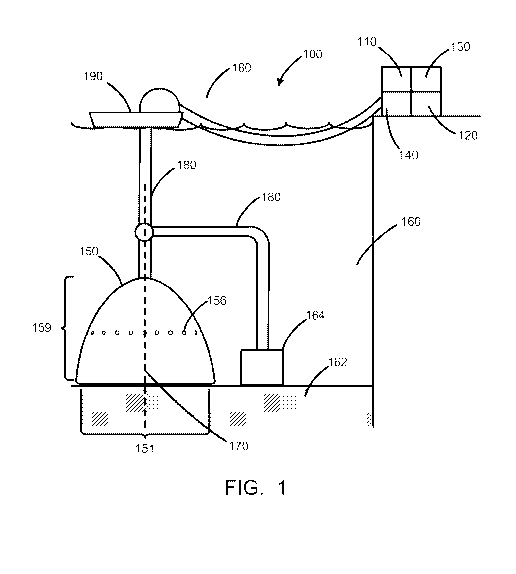
time. This lack of practicable energy storage results in the vast majority of
the
challenges faced by parties operating electrical grid(s).
[0004] With the
increased recognition that continued carbon emissions from burning
fossil fuels is unsustainable on multiple levels, and that proliferation
concerns exist for
nuclear power, it has become clear that relatively large amounts of renewable
energy
(RE) will be needed to provide power for the grid. Hydroelectric power, when
combined
with a reservoir, is one RE source that can be throttled up and down to match
the
varying power loads, also called "load-following". Geothermal and Ocean
Thermal
Energy Conversion are also good baseload RE resources, despite their limited
locations.
However, the solar wind, wave, tidal, and current energies are all
intermittent. Energy
1
CA 02935279 2016-06-27
WO 2015/108915
PCT/US2015/011314
storage is required for those sources to substantially contribute to the grid
energy
supply.
[0005] Cost
parameters of several leading storage technologies may be considered
for large scale energy systems. Each technology has its own cost drivers.
Pumped
hydroelectric, for example, has been used for many decades and is often
considered the
standard by which other grid-energy-storage ideas are judged. It is efficient,
consumes
no fuel upon harvesting the stored energy, but is constrained by geography. A
substantial elevation change and two reservoirs are typically required. Most
of the
viable sites in North America are considered to be already developed.
Regardless of
cost, it does not appear that pumped hydroelectric will be able to contribute
much
additional energy storage capacity. It is also fairly expensive in terms of
capital cost per
unit power ($/kW) but nonetheless is widely used when available because of the
fairly
low capital cost per unit energy ($/kWh).
[0006]
Considerable effort is going into "conventional" batteries, but most of that
effort is focused on electric vehicle energy storage, where weight is a
critical parameter.
As such, many of the "new" battery technologies are actually considerably more
expensive than can be tolerated for grid-energy-storage systems. Thus, these
batteries
for hybrid electric vehicles are often able to provide considerable power per
unit cost,
but are still very expensive per unit energy. Flow batteries are a newer
technology
where the chemicals are stored in tanks and reacted in systems similar to fuel
cells. The
cost of the fairly unusual chemicals used as the reactants leads to moderately
high cost
per unit energy and unit power.
[0007]
Compressed Air Energy Storage (CAES) is an attractive energy storage
technology that overcomes many drawbacks of known energy storage technologies.
The
conventional approach for CAES is to use a compressor to store the compressed
air
underground. The energy is harvested by expanding the compressed air through a
turbine. In this process, the air is mixed with natural gas, combusted and
expanded
through the turbine. The system operates at high pressure in order to take
advantage of
the modest volume of the underground cavern or aquifer. The result is a system
that
2
CA 02935279 2016-06-27
WO 2015/108915
PCT/US2015/011314
operates with constant volume and variable pressure during the storage and
retrieval
process, which results in extra costs for the compressor and turbine system,
since they
operate best at a single design pressure. The heating during compression and
the cooling
during expansion of air also require special attention in order to obtain
suitable
efficiencies.
[0008]
Conventional CAES reheats the air efficiently using combustion of natural
gas (often by absorbing heat from the gas turbine exhaust). Such systems often
have two
separate compressors and turbines. They therefore have a greater capital
expense, over
and above the cost of the natural gas. The result is that the power plant,
when utilizing
purchased off-peak power to charge the air reservoir, generates power with
about 'A the
use of natural gas per unit energy but with a moderately expensive set of
equipment and
higher fuel costs.
[0009] A need
exists to provide grid-scale energy storage that is more energy-
efficient, lower in cost, more responsive, and more geographically ubiquitous
than
traditional underground CAES.
3
CA 02935279 2016-06-27
WO 2015/108915
PCT/US2015/011314
SUMMARY OF THE INVENTION
[0010] In a
first aspect a compressed fluid energy storage system is provided
comprising a submersible fluid containment subsystem disposed longitudinally
along a
vertical axis when submerged and ballasted in a body of water and charged with
a
compressed working fluid, the fluid containment system comprising a
substantially flat
portion closing a domed portion; a compressor disposed in fluid communication
with
the fluid containment subsystem and configured to supply compressed working
fluid to
the fluid containment subsystem; and an expander disposed in fluid
communication
with the fluid containment subsystem and configured to receive compressed
working
fluid from the fluid containment subsystem and expand the compressed working
fluid;
wherein the fluid containment subsystem is at least in part flexible. The
compressor and
the expander may be the same device and the expander may be disposed to drive
an
electrical generator. The working fluid may be one or more of a compressible
gas, a
compressible liquid, and a supercritical fluid, and the compressible gas may
be air. The
substantially flat portion may be a substantially circular flat portion.
[0011] The
system may further comprise at least one exchange port disposed
generally in a shell of the fluid containment subsystem for allowing the
ingress of water
from the body of water into the fluid containment subsystem and for allowing
the egress
of water and materials from the fluid containment subsystem to the body of
water. The
at least one exchange port may be disposed in the shell of the fluid
containment
subsystem below a vertical location, the vertical location corresponding to a
predetermined lowest location to be occupied by compressed energy fluid in the
fluid
containment subsystem. The at least one exchange port may disposed in the
shell of the
fluid containment subsystem radially substantially closer to the vertical axis
than a
smallest radial distance from the vertical axis at which the flat portion
exhibits
substantial vertical curvature when the fluid containment system is in use.
The at least
one exchange port may a plurality of exchange ports and the plurality of
exchange ports
may separate the fluid containment subsystem into a separate upper portion and
separate
lower portion configured to be joined together with fittings.
4
CA 02935279 2016-06-27
WO 2015/108915
PCT/US2015/011314
[0012] The
fluid containment subsystem may further comprise a first inlet-outlet port
configured for placing the fluid containment subsystem in fluid communication
with the
compressor and the expander.
[0013] The
fluid containment subsystem may further comprise ballast material
disposed within a lower portion of the fluid containment subsystem. The
ballast material
may be sediment from the bed of the body of water. The system may further
comprise a
flushing conduit connected to the first inlet-outlet port inside the fluid
containment
subsystem and directed to the ballast material within the fluid containment
subsystem,
the flushing conduit disposed for using water to flush ballast material from
the fluid
containment subsystem through an exchange port into the body of water. The
flushing
conduit may be perforated proximate the inlet-outlet port. The inlet-outlet
port may be
disposed at a vertical apex of the fluid containment subsystem and the
vertical apex is
directed upward.
[0014] The
system may further comprise a compressed fluid conduit disposed to
provide the fluid communication between the fluid containment subsystem and
the
compressor and expander. The compressed fluid conduit may be flexible, semi-
flexible,
or jointed. The system may further comprise a support on the body of water for
supporting the compressed fluid conduit at at least one point to impart to the
compressed fluid conduit a catenary shape.
[0015] In a
further embodiment, the system may comprise a ballast subsystem for
weighting down the fluid containment subsystem on or proximate a bed of the
body of
water. The system may further comprise a ballast subsystem configured to rest
on the
bed of the body of water; a plurality of tethering points disposed on the
fluid
containment subsystem; and at least one tether attaching the ballast subsystem
to at least
one of the plurality of tethering points; wherein the weight of the ballast
subsystem is
greater than a buoyant force acting on the fluid containment subsystem.
[0016] The
compressed fluid energy storage system may comprise multiple
submersible fluid containment subsystems. At the level of an individual fluid
containment subsystem, the system may therefore comprise a further compressed
fluid
CA 02935279 2016-06-27
WO 2015/108915
PCT/US2015/011314
conduit and a further submersible fluid containment subsystem, wherein the
fluid
containment subsystem in fluid communication with the compressor is in fluid
communication with the further containment subsystem via the further
compressed fluid
conduit. The region of the fluid containment subsystem joined to the
compressed fluid
conduit may be rigid. The rigid region may comprise polyvinyl chloride or
other
materials resistant to saltwater.
[0017] The
compressed fluid energy storage system may further comprise a
substantially continuous barrier wall disposed on the bed of the body of water
around
the fluid containment subsystem and the barrier wall may be comprised of, for
example,
New Jersey barriers.
[0018] The
domed portion of the fluid containment subsystem may be a flexible
fluid storage portion and the material of the fluid storage portion may be a
flexible
membrane. The flexible membrane may comprise a composite material. The
composite
material may comprise a fluid containment subsystem within the body of water;
a
compressor disposed in fluid communication with the fluid containment
subsystem and
configured to supply compressed working fluid to the fluid containment
subsystem; an
expander disposed in fluid communication with the fluid containment subsystem
and
configured to (i) receive compressed working fluid from the fluid containment
subsystem and (ii) expand the compressed working fluid; and a fluid conduit
disposed
to place the fluid containment subsystem in fluid communication with the
compressor
and the expander. The system may further comprise a tensegrity structure
disposed to
entrap the fluid containment subsystem, wherein the ballast subsystem rests on
the
tensegrity structure. The tensegrity structure may be a hexagonal tensegrity
structure.
The tensegrity structure may be disposed to restrain the fluid containment
subsystem at
at least six points on an upper surface of the fluid containment subsystem.
The fluid
containment subsystem may be open at the bottom and be fastened to either the
bed of
the body of water or the base of the tensegrity structure.
[0019] In a
further aspect, a method for deployment of the compressed fluid energy
storage comprises transporting a fluid containment subsystem with a compressed
fluid
6
CA 02935279 2016-06-27
WO 2015/108915
PCT/US2015/011314
conduit attached to a location for the fluid containment subsystem without
ballast or
compression energy fluid; lowering the fluid containment subsystem to a bed of
a body
of water at the location using sufficient ballast to counter natural buoyancy;
configuring
the compressed fluid conduit between the fluid containment subsystem and a
compressor and expander; attaching a part of the compressed fluid conduit
remaining on
the surface of the body of water to a support to impart a catenary shape to
the
compressed fluid conduit; injecting ballast material into the fluid
containment
subsystem as a slurry; and pumping compressed energy fluid via the compressed
fluid
conduit to the fluid containment subsystem. The lowering the fluid containment
subsystem to a bed of the body of water may comprise disposing ballast
materials on the
bed of the body of water; and controllably pulling the fluid containment
subsystem to
the bed of the body of water.
[0020] In
another aspect, a submersible fluid containment subsystem is disposed
longitudinally along a vertical axis when submerged and ballasted with
internally
disposed ballast materials in a body of water and charged with a compressed
working
fluid, the fluid containment system comprising a substantially flat portion
closing a
domed portion, wherein (a) the fluid containment subsystem comprises at least
one
exchange portal disposed in a shell of the fluid containment subsystem at a
distance
along the vertical axis from the substantially flat portion; and (b) the domed
portion
proximate the substantially flat portion has a taper from a perimeter of the
substantially
flat portion towards the vertical axis. The taper may be based on the density
of the
ballast materials and on the distance. The taper may be large enough to
counter a
collapsing action of the ballast materials on a lower portion of the domed
portion when
a volume of the compressed working fluid in the fluid containment subsystem is
low.
7
CA 02935279 2016-06-27
WO 2015/108915
PCT/US2015/011314
BRIEF DESCRIPTION OF THE DRAWINGS
[0021] The above mentioned and other features and objects of this
invention, and the
manner of attaining them, will become more apparent and the invention itself
will be
better understood by reference to the following description of an embodiment
of the
invention taken in conjunction with the accompanying drawings, wherein:
[0022] Figure 1 shows a compressed fluid energy storage system.
[0023] Figure 2 shows part of Figure 1 in more detail.
[0024] Figure 3 shows a flow chart for a method of deploying a compressed
fluid
energy storage system
[0025] Figure 4 shows another embodiment of a compressed fluid energy
storage
system
[0026] Figure 5 shows a compressed fluid energy storage system based on a
tens egrity structure.
[0027] Corresponding reference characters indicate corresponding parts
throughout
the several views. Although the drawings represent embodiments of the present
invention, the drawings are not necessarily to scale and certain features may
be
exaggerated in order to better illustrate and explain the present invention.
The flow
charts are also representative in nature, and actual embodiments of the
invention may
include further features or steps not shown in the drawings. The
exemplification set out
herein illustrates an embodiment of the invention, in one form, and such
exemplifications are not to be construed as limiting the scope of the
invention in any
manner.
8
CA 02935279 2016-06-27
WO 2015/108915
PCT/US2015/011314
DETAILED DESCRIPTION
[0028] The
embodiments disclosed below are not intended to be exhaustive or limit
the invention to the precise form disclosed in the following detailed
description. Rather,
the embodiments are chosen and described so that others skilled in the art may
utilize
their teachings. United States Patent Application US 12/888,971 filed 23
September
2010 relates to the present specification and its disclosure is hereby
incorporated in the
present specification. The following United States Provisional Patent
applications,
namely U.S. Provisional Application 61/245,279 filed Sep. 23, 2009; U.S.
Provisional
Application 61/309,415 filed Mar. 1, 2010; U.S. Provisional Application
61/364,364
filed Jul. 14, 2010; and U.S. Provisional Application 61/364,368 filed Jul.
14, 2010 also
all related to the present invention and their disclosures are hereby
incorporated in the
present specification.
[0029] The term
"fluid" is used in the present specification to describe any
compressible gas or liquid such as for example without limitation air, CO2, or
the like,
including a supercritical fluid. In the present specification, the acronym
"CAES" is used
to describe not just compressed air energy storage systems, but also the more
general
compressed fluid energy storage systems. The term "body of water" is used in
the
present specification to describe for example without limitation an ocean,
sea, lake,
reservoir, gulf, harbor, inlet, river, or any other manmade or natural body of
depth great
enough to generate useful hydrostatic pressure by virtue of gravity. The term
"sediment"
is used in the present specification to describe marine material from the bed,
floor or
bottom the body of water and may include, by way of example, gravel, sand,
silt, clay,
mud, organic or other material settled onto the bed, floor or bottom of the
body of water.
[0030] The
present specification provides in a first embodiment a compressed fluid
energy storage (CAES) system 100, as shown in Figure 1, and in more detail in
Figure
2. CAES system 100 comprises a compressor 110 for compressing a working fluid,
an
expander 120 for expanding the fluid and generate thereby electric power in a
suitable
generator 130 driven by the expander 120. A suitable manifold shut-off valve
140
places either compressor 110 or expander 120 in fluid communication with
submersible
9
CA 02935279 2016-06-27
WO 2015/108915
PCT/US2015/011314
fluid containment subsystem 150 located on or proximate the bed 162 of body of
water
160, or shuts off all fluid communication between containment subsystem 150
and both
compressor 110 and expander 120. Containment subsystem 150 is disposed
longitudinally along a vertical axis 170 when submerged and ballasted in body
of water
160 and charged with a compressed working fluid. Fluid containment subsystem
150 is
at least in part flexible.
[0031]
Compressed fluid flows from fluid containment subsystem 150 to generator
130, or from compressor 110 to fluid containment subsystem 150 via compressed
fluid
conduit 180 and manifold shut-off valve 140. One skilled in the art will
recognize that a
compressed fluid storage vessel must be ballasted or anchored so it doesn't
float to the
surface when inflated with compressed working fluid. In different embodiments,
fluid
containment subsystem 150 is ballasted either by ballast material within its
own volume
155, or by a separate ballast subsystem, both of which are described in more
detail
below. A volume of compressed working fluid in the fluid containment subsystem
150
is stored nearly isobarically as a function of the amount of fluid therein and
as a
function of the depth of the fluid containment subsystem 150 within body of
water 160.
The hydrostatic pressure of surrounding water is the predominant restraining
parameter
for the compressed fluid, which is pressurized into the fluid containment
subsystem 150
via a compressor 110, valve 140, and compressed fluid conduit 180. Compressor
110
and expander 120 may be disposed underwater, or outside the body of water
either on
land, sea or in the air.
[0032] We turn
now to the flexible submersible fluid containment subsystem 150
located on or proximate the bed 162 of body of water 160. To the extent that
the fluid
containment subsystem 150 is flexible, its precise shape is dictated by
various factors,
including its manufactured shape, its depth within the body of water and
associated
hydrostatic pressure, the amount of compressed fluid within its volume, and by
whatever ballast arrangement is used to weigh it down. It is furthermore
affected by
how and where the ballast weight is applied to containment subsystem 150.
Despite the
variation based on these listed factors, the submerged fluid containment
subsystem 150
comprises, when charged with the compressed working fluid and suitably
ballasted, a
CA 02935279 2016-06-27
WO 2015/108915
PCT/US2015/011314
substantially flat portion 151 closing a substantially paraboloid,
ellipsoidal, or conically
shaped portion, which we refer to in this specification as the "domed portion"
159, and
is disposed longitudinally along a vertical axis under these conditions. In
some
embodiments, the flat portion 151 may be substantially circular. The internal
volume of
fluid containment subsystem 150 comprises a fluid storage portion 152
generally in the
top of the domed portion 159. The shell of fluid containment subsystem 150 may
comprise, at least in part, a flexible membrane, for example a composite,
polymer
membrane comprising glass fibers and polyethylene matrix. Other strong
polymers to
consider include polyurethane, carbon, acrylic, acrylene, glass, polyester,
etc. The fluid
storage portion 152 may be specifically flexible.
[0033] The term
"shell" is used here to describe the portion of the fluid containment
subsystem 150 that separates the internal volume of the fluid containment
subsystem
150 from the body of water 160. The term "substantially paraboloid,
ellipsoidal, or
conically shaped" is used in the present specification to describe the hollow
three-
dimensional shape of the domed portion that has substantial rotational
symmetry about a
longitudinal axis and is either substantially conic in shape, or approximates
in cross-
section along that longitudinal axis a parabola, or approximates a portion of
a
hemisphere of an ellipsoid having the longitudinal axis as semi-major axis. It
is to be
particularly understood that, when in operation, the domed portion 159 may
exhibit
convex deformation under pressure from the compressed working fluid stored
within it,
thereby deviating the shape from that of a pure conic section. Similarly, it
may exhibit
deformation when underinflated with compressed working fluid.
[0034] The
substantially circular flat portion may be at least in part an oblate
ellipsoid or oblate paraboloid and may be completely flat over a substantial
part of the
bottom. It is to be particularly understood that, when in operation, the
substantially
circular flat portion may exhibit deformation under pressure from materials or
gasses
contained within it. In this way a substantially oblate ellipsoid or oblate
paraboloid
"circular flat portion" may be flattened over a substantial fraction of its
surface.
11
CA 02935279 2016-06-27
WO 2015/108915
PCT/US2015/011314
[0035] The
substantially circular flat portion 151 is joined to the domed portion 159
by a transition portion 154 that varies in space from the circular flat
portion 151 to the
domed portion 159 and is everywhere contiguous with both the flat portion 151
and the
domed portion 159.
[0036] In more
general embodiments, fluid containment subsystem 150 can
comprise more general spheroidal, oblate spheroidal, ellipsoidal, droplet-
like, or other
rectilinear or other simply connected shapes.
[0037] Fluid
containment subsystem 150 comprises at least one exchange port 156
disposed in the shell of the fluid containment subsystem 150 for allowing the
ingress of
water from the body of water 160 into the fluid containment subsystem 150 and
for
allowing the egress of water and materials from the fluid containment
subsystem 150 to
the external body of water 160. As fluid containment subsystem 150 is filled
with
compressed working fluid, the fluid, being less dense than the surrounding
water, takes
up residence in the fluid storage portion 152 and the lower limit of the
bubble 153 of
compressed working fluid extends downward ever further. The vertical pressure
due to
the density difference between the compressed working fluid and the
surrounding water
deforms the fluid storage portion 152 in this process. When the lower limit
166 of the
bubble of compressed working fluid reaches the at least one exchange port 156,
excess
compressed working fluid is vented through the at least one exchange port 156.
In
figures 1 and 2, a number of exchange ports 156 are shown. The exchange
port(s) 156
may be disposed in the shell of the fluid containment subsystem 150 below a
vertical
location corresponding to a predetermined lowest location to be occupied by
compressed energy fluid bubble 153 in the fluid containment subsystem 150.
[0038] In
particular, in some embodiments, the at least one exchange port(s) 156
may be disposed in the shell of the fluid containment subsystem 150 radially
at a
distance d2 substantially closer to the vertical axis 170 of fluid containment
subsystem
150 than a smallest radial distance dl from the vertical axis 170 at which the
flat portion
151 exhibits substantial vertical curvature. That point of curvature 157 of
flat portion
151 is indicated in Figure 2. This specific arrangement prevents the ballast
material
12
CA 02935279 2016-06-27
WO 2015/108915
PCT/US2015/011314
from collapsing the lower portion of the domed portion 159 and thereby
effectively
collapsing the flexible structure of fluid containment subsystem 150 as a
whole.
[0039] When
there is very little vertical tension in the dome portion 159, a potential
exists for the lower portion of the dome portion 159 to collapse under the
pressure of
ballast materials 155. Such a situation may pertain during the early phases of
injection
of compressed energy fluid into subsystem 150 when there may be very little
compressed energy fluid present in compressed energy fluid bubble 153, while a
substantial load of ballast material 155 might be present. The shape of the
lower portion
of fluid containment subsystem 150 has to be of such shape as will assist in
preventing
collapse under these circumstances.
[0040] When the
compressed energy fluid bubble 153 in fluid storage portion 152 is
at its maximum capacity, the vertical forces in the shell of the dome portion
159 will be
large, and the amount of ballast materials 155 in the lower portion of
subsystem 150 has
to be sufficient to counterbalance those forces to keep subsystem 150
submerged. This
requirement argues for a large amount of ballast materials 155 within the
confines of the
lower portion of subsystem 150, increasing thereby the potential for collapse
of the
lower portion of the dome portion 159 if the injection of compressed energy
fluid is
near a minimum while ballast is near a maximum. These considerations define
conditions upon the shape of the lower portion of dome portion 159.
[0041] To
ensure that the introduction of extra compressed fluid to the vessel does
not exceed the downward ballast force, the location of the exchange ports and
the
shapes of the upper and lower portions of the vessel are selected to preclude
this
possibility. Changing levels of compressed energy fluid in the fluid storage
portion 152
change the vertical tension in dome portion 159. Considerable variation in the
tension
can substantially change the shape of the overall fluid containment subsystem
150.
Higher tension, associated with the storage of more energy storage fluid,
tends to move
point of curvature 157 in towards the vertical axis 170 and correspondingly
increases
the amount of downward force on the shell of fluid containment subsystem 150
radially
outboard of point 157.
13
CA 02935279 2016-06-27
WO 2015/108915
PCT/US2015/011314
[0042] The
shape of the sidewall of the lower portion of subsystem 150 can affect
whether that sidewall is changing position substantially as a function of the
amount of
compressed energy fluid in the fluid storage portion 152. If the sidewall
shape is such
that the upward force on the sidewall in the region below and proximate the
exchange
ports 156 is similar or greater than the downward force on the sidewall
proximate and
outboard of point of curvature 157, then a relatively stable shape for the
lower portion
of subsystem 150 can be maintained, independent of the amount of compressed
fluid in
the vessel. As a result, the sidewall does not collapse vertically when there
are only
small amounts of compressed energy fluid in the fluid storage portion 152, as
will occur
during charging of the system with working fluid from a substantially empty
state, or
when the working fluid is extracted to very low levels. This also allows
considerable
freedom in the exact shape of the upper portions of fluid containment
subsystem 150. In
view of the above, if the radial location d2 is substantially inboard of the
radial location
dl, then the forces generated by the ballast, which is denser than the water,
maintains
the generally vertical orientation of the sidewall for the full range of
compressed energy
fluid levels that may occur. The location of the exchange ports 156 directly
affects the
height, and thereby the weight, of the ballast materials 155 in fluid
containment
sub system 150.
[0043] The flat
portion 151 and the lower portion of the dome portion 159 below the
at least one exchange port 156, may be viewed as being vertically tapered
substantially
inward to the vertical axis 170. The degree of taper is based on the height
above the flat
portion of the at least one exchange port 156, and on the density of the
ballast materials
155 and is chosen to be sufficient to counter the collapse of the lower
portion of the
dome portion 159 in case of low working fluid volume in the fluid storage
portion 152.
Submersible fluid containment subsystem 150 may be viewed as disposed
longitudinally along vertical axis 170 when submerged and ballasted with
internally
disposed ballast materials 155 in body of water 160 and charged with a
compressed
working fluid in fluid storage portion 152, fluid containment system 150
comprising
substantially flat portion 151 closing domed portion 159, wherein (a) fluid
containment
subsystem 150 comprises at least one exchange portal 156 disposed in a shell
of fluid
14
CA 02935279 2016-06-27
WO 2015/108915
PCT/US2015/011314
containment subsystem 150 at a distance along vertical axis 170 from
substantially flat
portion 151; (b) domed portion 159 proximate substantially flat portion 151
has a taper
from a perimeter of substantially flat portion 151 towards vertical axis 171;
and (c) the
taper is based on a density of the ballast materials 155 and on the distance.
The taper is
large enough to counter a collapsing action of the ballast materials on a
lower portion of
the domed portion when a volume of the compressed working fluid in the fluid
containment subsystem is low.
[0044] Fluid
containment subsystem 150 further comprises a first inlet-outlet port
158 configured for placing the fluid containment subsystem in fluid
communication
with the compressor and the expander. First inlet-outlet port 158 may be
located in a
variety of positions on fluid containment subsystem 150, though one
particularly useful
location is at the vertical apex 182 of the domed portion 159 of the fluid
containment
subsystem 150 containing the compressed energy fluid bubble 153.
[0045] In a
first general embodiment, the ballast for the fluid containment subsystem
150 comprises ballast material 155 within the fluid containment subsystem 150,
the
ballast material 155 resting on the flattened bottom of fluid containment
subsystem 150.
The ballast material 155 may be supplied via compressed fluid conduit 180. In
other
embodiments the ballast material 155 may be supplied via a separate ballast
supply
conduit (not shown). The ballast material may be sediment from the bed 162 of
the body
of water 160 proximate fluid containment subsystem 150. To this end a
submersible
pump 164 may be located proximate fluid containment subsystem 150 to ingest
sediment and supply it via sediment conduit 168 and compressed fluid conduit
180 or
the separate ballast supply conduit (not shown). If suitable ballast is not
available
locally, it may be sourced elsewhere, transported by surface vessel to the
location of
fluid containment subsystem 150, and supplied to fluid containment subsystem
150 via
compressed fluid conduit 180. Sediment ballast may be pumped into the fluid
containment subsystem 150 as a slurry. In one embodiment a fine aggregate such
as
sand has the ability to be pumped in a water aggregate slurry for rapid and
continuous
filling. Excess ballast slurry will spill through exchange port(s) 156.
CA 02935279 2016-06-27
WO 2015/108915
PCT/US2015/011314
[0046] It will
be understood that, with compressed fluid bubble 153 confined to fluid
storage portion 152 of containment subsystem 150, and with the ballast
material 155
substantially confined to the portion of containment subsystem 150 below the
exchange
port(s) 156, a layer of water 168 exists in the general vicinity of exchange
port(s) 156.
This leads to an embodiment in which containment subsystem 150 is not a
contiguous
"monocoque" closed structure, but instead comprises separate upper and lower
portions
bearing fittings that allow the upper and lower portions be engaged with each
other. The
spaces between the fittings then serve the same function as exchange port(s)
156 of
Figure 1 and Figure 2. This is made possible by the fact that the general
region of
exchange port(s) 156 has no confinement role with respect to either ballast or
compressed energy fluid, but, rather, assist in balancing the hydrostatic
pressure inside
and outside containment subsystem 150 in the region between the ballast
material 155
and the compressed fluid bubble 153.
[0047]
Compressed fluid conduit 180 may be one or more of flexible, semi-flexible,
and jointed. CAES system 100 may comprise a support 190 on the body of water
160
for supporting the compressed fluid conduit 180 at least one point to impart
to the
compressed fluid conduit 180 a catenary shape.
[0048] The
compressed energy fluid bubble 153 in fluid containment subsystem 150
may be linked to another compressed energy fluid bubble in a further fluid
containment
subsystem 150' by a further compressed fluid conduit. This allows for a
plurality of
fluid containment subsystems 150 to be operated in series. Alternatively, a
plurality of
fluid containment subsystems may be linked independently to compressor 110 for
and
expander 120 in order to operate the plurality of fluid containment subsystems
in
parallel. According to one embodiment of the invention, compressed fluid
storage
systems may be configured in a modular fashion to allow portions of the
overall system
to be temporarily shut down for maintenance, or repair, or permanently
decommissioned, without having to shut down the overall system.
[0049] Fluid
containment subsystem 150 may further comprise a flushing conduit
185 connected to the first inlet-outlet port inside the fluid containment
subsystem and
16
CA 02935279 2016-06-27
WO 2015/108915
PCT/US2015/011314
directed to the ballast material within the fluid containment subsystem, the
flushing
conduit 185 disposed for using water to flush ballast material 155 from the
fluid
containment subsystem through at least one of the exchange ports 156 into the
body of
water 160.
[0050] In a
further aspect, a method for deployment of, for example, the compressed
fluid energy storage (CAES) system 100, comprises, as shown in Figure 3,
transporting
[310] fluid containment subsystem 150, with compressed fluid conduit 180
attached, to
the location for fluid containment subsystem 150 without ballast or air,
lowering [320]
fluid containment subsystem 150 to the bed 162 of a body of water 160 using
enough
ballast to counter natural buoyancy. The lowering may be, for example without
limitation, by first disposing ballast materials on the bed 162 of the body of
water 160
and then controllably pulling the fluid containment subsystem 150 to the bed
162 of the
body of water 160.
[0051]
Compressed fluid conduit 180 is configured [330] between fluid containment
subsystem 150 and compressor 110. The part of compressed fluid conduit 180
remaining on the surface of body of water 160 is attached [340] to support 190
to impart
a catenary shape to compressed fluid conduit 180.
[0052]
Compressed fluid conduit 180 may be weighted in a distributed way along its
surface length, for example from shore. Alternatively, the hose can be
ballasted to be
heavier than water during first half of the hose from the surface to
approximately the
midpoint, which forms a catenary shape. The second half of the hose is buoyant
from
the approximate midpoint to the sea floor, where fluid containment subsystem
150 is
disposed, for an inverse catenary to result in an S shape that extends and is
resilient to
shifting winds and currents and boat/platform movements.
[0053] Once
fluid containment subsystem 150 is deployed and configured on the
bottom of the body of water 160, ballast is injected [350] into fluid
containment
subsystem 150 as a slurry, either from the bed 162 of the body of water 160
proximate
containment subsystem 150 via compressed fluid conduit 180 using the
submersible
pump 164, or from a surface vessel via compressed fluid conduit 180.
Overfilled
17
CA 02935279 2016-06-27
WO 2015/108915
PCT/US2015/011314
sediment spills out of fluid containment subsystem 150 via exchange port(s)
156 onto
the bed 162 of body of water 160. In this way, the bottom portion of fluid
containment
subsystem 150 is ballasted with sediment, while the top portion is not filled
with
sediment due to the holes.
[0054] Once
this process is complete, air is pumped [360] via compressed fluid
conduit 180 down to fluid containment subsystem 150. The air is stored in
fluid storage
portion 152 of fluid containment subsystem 150. The overfill air goes out via
exchange
port(s) 156, protecting fluid containment subsystem 150 from overcapacity or
overpressure. By monitoring the exact pressure of the system when air is not
flowing,
the fill level of fluid containment subsystem 150 can be determined, and its
percentage
full or empty can be determined as well.
[0055] In one
embodiment, connection fittings can connect a top portion of fluid
containment subsystem 150 to a bottom portion of fluid containment subsystem
150.
Spaces between the fittings can serve as exchange port(s). Divers or Remote
Operating
Vehicles (ROVs) can attach or remove fittings for maintenance as needed to
separate
the top portion from the bottom portion. Meridional slices can be attached to
each other
for construction of fluid containment subsystem 150. They can be melted,
fused, glued,
stitched or seamed together. The seams can be waterproofed. The compressed
fluid
conduit 180 may engage with inlet-outlet port 158 at the apex of the fluid
containment
sub system 150.
[0056] If it
is desired to retrieve fluid containment subsystem 150, water may be
blown down compressed fluid conduit 180 and through flushing conduit 185,
directing a
jet of water towards the ballast 155. A sufficiently forceful application of
water will
entrain the ballast 155 and cause the ballast 155 to flow out of fluid
containment
subsystem 150 via exchange port(s) 156. Once sufficient ballast 155 has been
emptied,
the vessel is once again filled with air. The air lifts the vessel off the
seafloor, since it is
no longer ballasted, and lifts it to the surface. Excess air of expansion will
leak out the
exchange port(s) 156, ensuring no excess pressure build-up.
18
CA 02935279 2016-06-27
WO 2015/108915
PCT/US2015/011314
[0057] It is
also possible to have a drawstring or line or cord through an air hose (not
shown) that is connected, for example, near the bottom of fluid containment
subsystem
150 and is drawn up to better direct the air hose water jet onto the ballast
155 to divert
some of the sand from the vessel to the outside. During emptying, the
drawstring
tension is applied, shortening the drawstring and bringing the air hose near
the bottom
of fluid containment subsystem 150.
[0058] There
are two first-order structural forces at work on fluid containment
subsystem 150. The buoyancy force due to the air in the fluid storage portion
152 of
fluid containment subsystem 150 creates vertical stress in the membrane. The
weight of
the ballast in the bottom of fluid containment subsystem 150 provides the
opposing
force in the lower portion of fluid containment subsystem 150. Vertical fiber-
reinforced
fabric orientations can react these primary stresses against each other with
minimal
amounts of material. The apex of fluid containment subsystem 150 may comprise
a
PVC flange or other material.
[0059] As air is pumped from the surface down into fluid containment subsystem
150, the interface of air to water 166 descends. The hydrostatic pressure can
be
measured at the surface as a function of time until it levels off, indicating
that surplus air
is being released through exchange port(s) 156 to the surface. Thus the
pressure can
provide a detailed indication of the fill level of fluid containment subsystem
150.
[0060] In a
further embodiment shown in Figure 4, a fluid containment subsystem
450 for use in a compressed fluid energy storage (CAES) system of the general
type
described at the hand of in Figure 1 may comprise a separate ballast subsystem
455 for
ballasting the fluid containment subsystem 450 proximate a bed 462 of body of
water
460. Fluid containment subsystem 450 is taken to be of the general type
described at the
hand of Figure 1. For the sake of clarity, all equipment beyond fluid
containment
subsystem 450 is omitted from Figure 4. In this embodiment, there is no
substantial
amount of ballast materials in fluid containment subsystem 450. The ballast
subsystem
is configured to rest on the bed 462 of the body of water 460. A plurality of
tethering
points 465 are disposed on the fluid containment subsystem 450 and allow at
least one
19
CA 02935279 2016-06-27
WO 2015/108915
PCT/US2015/011314
tether 467 to attach the ballast subsystem 455 to at least one of the
plurality of tethering
points 465. The weight of the ballast subsystem 455 is chosen to be greater
than the
buoyant force acting on the fluid containment subsystem 450. It is clear that
this
configuration allows the compressed energy fluid bubble 453 to extend much
further
down into fluid containment subsystem 450 than in the configuration of Figure
1 and 2.
The exchange ports 456 can therefore be positioned lower down the dome portion
of
fluid containment subsystem 450. The balance of the volume within containment
subsystem 450 is taken up largely by water 468.
[0061] In
another embodiment, shown in Figure 5, a compressed fluid energy storage
system 500 comprises a flexible fluid containment subsystem 550 submersible in
a body
of water 560; a separate ballast system 555 disposed above the submersible
fluid
containment subsystem 550 within the body of water 560; a compressor 510
disposed in
fluid communication with the fluid containment subsystem 550 and configured to
supply compressed working fluid to the fluid containment subsystem 550; an
expander
520 disposed in fluid communication with the fluid containment subsystem 550
and
configured to receive compressed working fluid from the fluid containment
subsystem
550 and expand the compressed working fluid to generate thereby electric power
in a
suitable generator 530 driven by the expander 520; and a fluid conduit 580
disposed to
place the fluid containment subsystem 550 in fluid communication with the
compressor
510 and the expander 520. A suitable manifold shut-off valve 540 places either
compressor 510 or expander 520 in fluid communication with submersible fluid
containment subsystem 550 located on or proximate the bed 562 of body of water
560,
or shuts off all fluid communication between containment subsystem 550 and
both
compressor 510 and expander 520. Compressor 510 and expander 520 may be
disposed
underwater, or outside the body of water either on land, sea or in the air.
[0062] System
500 may comprise a support 590 on the body of water 560 for
supporting the compressed fluid conduit 580 at least one point to impart to
the
compressed fluid conduit 580 a catenary shape. The fluid containment subsystem
550
can be entirely composed of reinforced polymer fabric.
CA 02935279 2016-06-27
WO 2015/108915
PCT/US2015/011314
[0063] The
system 500 may further comprise a tensegrity structure 552 disposed to
entrap the fluid containment subsystem 550. The tensegrity structure 552 may
be
comprised of compression members 553 and tension members 554. In particular,
the
ballast subsystem 555 may rest on the tensegrity structure 552. The tensegrity
structure
may be selected to allow close-packing, stability and other advantages. The
tensegrity
structure may be composed of Fiber-crete compressional bars. By way of non-
limiting
example shown in Figure 500, the tensegrity structure 552 may be a hexagonal
tensegrity structure, and restrains the fluid containment subsystem 550 at at
least six
points on the upper surface of the fluid containment subsystem 550. In one
embodiment,
shown in Figure 5, the fluid containment subsystem 550 is open at the bottom
and is
fastened to the bed 562 of the body of water 560 or to the base of the
tensegrity
structure 552. A plurality of hexagonal tensegrity structures 552 can be
placed in a
close-packed arrangement, filling the area of the bed 562 of the body of water
560. This
increases stabilization of the structures against overturning. The tensegrity
structures
552, and especially arrays of them, can hold large amounts of compressed
working fluid
and ballast. Arrays of tensegrity structures 552 comprise a strong and
lightweight
structure. Sediment may be employed as ballast material and may be dredged and
dropped by a barge. Alternatively, local sediment in the vicinity of the
tensegrity
structure 552 may be pumped into ballast subsystem 555 using a submersible
pump (not
shown).
[0064] The
disclosed compressed fluid energy storage systems have cost advantages
and/or allow systems to be operated with significant cost advantages in
locations
currently used for underwater compressed air energy storage as well as
locations not
previously economically exploitable with prior art CAES components and
systems.
Ballast materials for use in the various embodiments can be sediment,
including in-situ
sediment, which may include for example gravel, sand, silt, clay, mud, organic
or other
material settled onto the floor of the sea. Other ballast materials can be
aggregate,
concrete or a hybrid such as concrete and sediment, steel and sediment, or
steel,
concrete and sediment.
21
CA 02935279 2016-06-27
WO 2015/108915
PCT/US2015/011314
[0065]
Aggregate can be brought from shore, either be being pumped in through an
air hose or brought by ship or barge to the location and pumped into the
ballast
containment feature (air vessel or ballast compartment). The piping and air
hoses must
carry the weight of sediment-loaded water without disturbing the orientation
of the fluid
containment subsystem to weight and mass flow thrust. Concrete can be cast
either
onshore, offshore on a ship or vessel, or underwater. If cast onshore the form
can remain
on the concrete piece, e.g. using culvert piping as casting. Hybrid forms
using
combinations of these materials may also be used. One hybrid is to use
concrete and
sediment. Another hybrid is to use steel and sediment. Yet another hybrid is
to use steel,
concrete, and sediment. These variations offer advantages in ballast material
cost which
can be optimized for any specific location. The cost of ballast delivery to
its final
location can also be optimized for sites depending on their specific
conditions by using
one or more of these variations. For example, the use of an axisymetric design
for the
fluid containment subsystem that can be ballasted from a single point with
overflow
features generally insures a pragmatically uniform and sufficient depth of
ballast exists
over the lower section of the fluid containment subsystem.
[0066] The
approach to deployment and its function, as described in this
specification, offers a tremendous cost advantage for embodiments, which do
not
require remotely piloted equipment and/or where the needed equipment is modest
in
scale. Deployment costs are also determined by the choice of material and can
be
significantly reduced by using in situ sediment. This ballast-to-air
compartment
structure and technique offers is efficient and therefore offers an advantage
in cost. It is
also extremely robust, as explained below. An even greater cost advantage is
realized if
no remotely piloted equipment is needed or if ROV use is minimized. The fluid
containment subsystems and their deployment with air hoses and ballast is
additionally
robust by providing resistance to water currents, marine life attack through
e.g.
encrustation or biting, corrosion, sabotage, and/or inadvertent problems such
as fishing
equipment entanglement. A barrier wall may be disposed on the bed of the body
of
water around the fluid containment subsystem to form a substantially
continuous barrier
around the fluid containment subsystem. For example, an energy storage region
on the
22
CA 02935279 2016-06-27
WO 2015/108915
PCT/US2015/011314
seafloor may be protected from bottom trawling by a perimeter of New Jersey
concrete
barriers or suitable equivalent.
[0067]
Therefore, according to one embodiment of the invention, a compressed fluid
energy storage system is provided comprising a submersible fluid containment
subsystem disposed longitudinally along a vertical axis when submerged and
ballasted
in a body of water and charged with a compressed working fluid, the fluid
containment
system comprising a substantially flat portion closing a domed portion; a
compressor
disposed in fluid communication with the fluid containment subsystem and
configured
to supply compressed working fluid to the fluid containment subsystem; and an
expander disposed in fluid communication with the fluid containment subsystem
and
configured to receive compressed working fluid from the fluid containment
subsystem
and expand the compressed working fluid; wherein the fluid containment
subsystem is
at least in part flexible.
[0068]
According to another embodiment of the invention, a submersible fluid
containment subsystem is disposed longitudinally along a vertical axis when
submerged
and ballasted with internally disposed ballast materials in a body of water
and charged
with a compressed working fluid, the fluid containment system comprising a
substantially flat portion closing a domed portion, wherein (a) the fluid
containment
subsystem comprises at least one exchange portal disposed in a shell of the
fluid
containment subsystem at a distance along the vertical axis from the
substantially flat
portion; and (b) the domed portion proximate the substantially flat portion
has a taper
from a perimeter of the substantially flat portion towards the vertical axis.
The taper
may be based on the density of the ballast materials and on the distance. The
taper may
be large enough to counter a collapsing action of the ballast materials on a
lower portion
of the domed portion when a volume of the compressed working fluid in the
fluid
containment subsystem is low.
[0069]
According to yet another embodiment of the invention, a compressed fluid
energy storage system comprises a flexible fluid containment subsystem
submersible in
a body of water; a separate ballast system disposed above the submersible
fluid
23
CA 02935279 2016-06-27
WO 2015/108915
PCT/US2015/011314
containment subsystem within the body of water; a compressor disposed in fluid
communication with the fluid containment subsystem and configured to supply
compressed working fluid to the fluid containment subsystem; an expander
disposed in
fluid communication with the fluid containment subsystem and configured to
receive
compressed working fluid from the fluid containment subsystem and expand the
compressed working fluid; and a fluid conduit disposed to place the fluid
containment
subsystem in fluid communication with the compressor and the expander.
[0070]
According to yet still another embodiment of the invention, a method for
deployment of the compressed fluid energy storage comprises transporting a
fluid
containment subsystem with a compressed fluid conduit attached to a location
for the
fluid containment subsystem without ballast or compression energy fluid;
lowering the
fluid containment subsystem to a bed of a body of water at the location using
sufficient
ballast to counter natural buoyancy; configuring the compressed fluid conduit
between
the fluid containment subsystem and a compressor and expander; attaching a
part of the
compressed fluid conduit remaining on the surface of the body of water to a
support to
impart a catenary shape to the compressed fluid conduit; injecting ballast
material into
the fluid containment subsystem as a slurry; and pumping compressed energy
fluid via
the compressed fluid conduit to the fluid containment subsystem. The lowering
the fluid
containment subsystem to a bed of the body of water may comprise disposing
ballast
materials on the bed of the body of water; and controllably pulling the fluid
containment
subsystem to the bed of the body of water.
[0071] While
this invention has been described as having an exemplary design, the
present invention may be further modified within the spirit and scope of this
disclosure.
This application is therefore intended to cover any variations, uses, or
adaptations of the
invention using its general principles. Further, this application is intended
to cover such
departures from the present disclosure as come within known or customary
practice in
the art to which this invention pertains.
24