Note : Les descriptions sont présentées dans la langue officielle dans laquelle elles ont été soumises.
CA 02936673 2016-07-12
[DESCRIPTION]
[Invention Title]
TRANSPORTATION CONTAINER BLOWER FOR MORTALITY
PREVENTION AND WELFARE DURING LIVESTOCK TRANSPORTATION
[Technical Field]
The present invention relates to a blower which is installed at a
transportation
container (including a screen fence and tent) for livestock hygiene, and
particularly,
to a blower for transportation, which is installed at a transportation means
to
maintain internal temperature and humidity, to forcibly discharge harmful gas,
and
1 0 thereby to transport livestock or the like in a pleasant environment.
[Background Art]
Generally, consumption of livestock bred for meat in a stable is increasing
according to an improvement of dietary life style and a development of a
westernized
eating-out culture, and thus breeding of livestock for meat is becoming
widespread
1 5 and commercialized.
Livestock for meat are mainly bred on outskirts of a city which are less-
affected by odors, waste or the like.
A rancher that breeds livestock for meat has need of a livestock
transportation
means which transports cultured livestock to a slaughterhouse or a livestock
market
20 for the purpose of slaughter or economic profit.
Since a general livestock transportation means has no shield, an odor may be
discharged to an outside during livestock transportation, and an external
appearance
thereof may be aesthetically repellent to people. To prevent such problems,
transportation is mostly performed while a cover is appropriately provided.
1
CA 02936673 2016-07-12
However, when livestock is transported using a vehicle, a ship or the like,
livestock transportation is performed using a method in which a cargo box is
partially
opened, or the like, or in a state in which appropriate equipment is installed
to
prevent mortality of the livestock due to high heat generated from the
livestock and
various harmful gases generated from the livestock and an inside of the cargo
box.
In such a livestock transportation method, due to high heat and humidity and
harmful gases, weight of livestock located at an edge side is reduced, and
meat
therefrom is degraded regardless of season, the heat in summer, or the cold
wind in
winter. Most livestock mortality occurs during a transportation and shipping
process.
[Disclosure]
[Technical Problem]
The present invention is to evenly discharge internal air in every corner of a
container by mounting a blowing means and a blowing pipe at an upper portion
thereof, and to pleasantly maintain the internal air of the container by
forcing
16 external air to be introduced and discharged, thereby maintaining a
hygienic welfare
of livestock in an optimum state while quarantining during livestock
transportation
so that mortality of the livestock is prevented.
Also, the present invention is directed to providing a transportation
container
blower which is able to increase a distribution level of suctioned fresh air
by
installing an easily detachable auxiliary multi-section suctioning rod.
[Technical Solution]
One aspect of the present invention provides a transportation container
blower for mortality prevention and welfare during livestock transportation,
including a body (100) connected to a transportation means and having a space
in
2
CA 02936673 2016-07-12
which livestock is accommodated therein and a first blowing port (110) formed
at
each of lower portions of both sides thereof to be opened; a blowing path
(200)
installed at an upper end of the body (100) to be long in a longitudinal
direction
thereof and having a second blowing port (210) which is in communication with
an
inside of the body (100) and formed at a lower end or a side surface thereof;
and a
blowing means (300) installed at the body (100) and connected to the blowing
path
(200), wherein the blowing means (300), when operated, forces air in the body
(100)
to be blown through the first blowing port (110) and the second blowing port
(210),
thereby quarantining the livestock accommodated in the body (100) and
pleasantly
maintaining a hygienic condition of the livestock so that mortality of the
livestock is
prevented.
A plurality of second blowing ports (210) may be disposed to be spaced apart
from each other in a longitudinal direction of the blowing path (200), and
also may
be formed so that a width of each thereof shrinks toward the blowing means
(300).
The blowing means (300) may be installed at a center of an upper end of the
body (100).
The transportation container blower may further include an opening and
closing cover (400) which is installed at the first blowing port (110) to open
and
close the first blowing port (110), and the opening and closing cover (400)
may open
the first blowing port (110) to forcibly blow impure air in the body (100)
when the
blowing means (300) is operated.
[Advantageous Effects]
The transportation container blower for livestock hygiene of the present
invention as described above has the following effects.
3
CA 02936673 2016-07-12
Since the blowing means 300 is installed at the center of the upper end of the
body 100 and connected to the blowing path 200, the air in the body 100 is
evenly
suctioned through the second blowing ports 210 and then discharged to the
outside,
and the internal environment is pleasantly maintained by introducing the
external air
inside through the first blowing ports 110, and thus the livestock is
maintained in an
optimum state during livestock transportation.
Since the second blowing port 210 is formed so that a width thereof shrinks
toward the blowing means 300, air-blowing is evenly performed at every surface
and
corner of the body 100 when the blowing means 300 is operated.
1 D [Description of Drawings]
FIG. 1 is a perspective view of a transportation container blower for
livestock
hygiene according to an embodiment of the present invention.
FIG. 2 is a structural cross-sectional view taken along A-A of FIG. 1.
FIG. 3 is a structural cross-sectional view taken along B-B of FIG. 2.
FIG. 4 is a view illustrating a state in which a second blowing port of the
present invention is formed at a lower portion and a side surface.
FIG. 5 is a perspective view of a guide wing according to another
embodiment of the present invention.
FIGS. 6 and 7 are partial cross-sectional views illustrating a usage state of
a
multi-section suctioning pipe according to still another embodiment of the
present
invention.
[Modes of the Invention]
Hereinafter, a transportation container blower for mortality prevention and
welfare during livestock transportation according to exemplary embodiments of
the
4
CA 02936673 2016-07-12
present invention will be described in detail with reference to the
accompanying
drawings.
It should be understood that the terms used in the specification and the
appended claims are not to be construed as being limited to general and
dictionary
meanings, but should be interpreted based on the meanings and concepts
corresponding to technical aspects of the present invention on the basis of
the
principle that the inventor is allowed to define terms appropriately for the
best
explanation. Therefore, the description proposed herein is simply a preferable
example for the purpose of illustrations only and is not intended to limit the
scope of
the invention, so it should be understood that other equivalents and
modifications
could be made thereto without departing from the spirit and scope of the
invention.
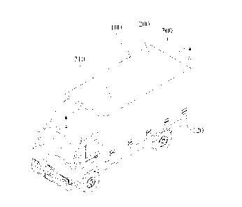
FIG. 1 is a perspective view of a transportation container blower for
livestock
hygiene according to an embodiment of the present invention, FIG. 2 is a
structural
cross-sectional view taken along A-A of FIG. 1, FIG. 3 is a structural cross-
sectional
view taken along B-B of FIG. 2, FIG. 4 is a view illustrating a state in which
a
second blowing port of the present invention is formed at a lower portion and
a side
surface, FIG. 5 is a perspective view of a guide wing according to another
embodiment of the present invention, and FIGS. 6 and 7 are partial cross-
sectional
views illustrating a usage state of a multi-section suctioning pipe according
to still
another embodiment of the present invention.
A transportation container blower for livestock hygiene according to an
embodiment of the present invention illustrated in FIGS. 1 to 4 includes a
body 100,
a blowing path 200, a blowing means 300, and an opening and closing cover 400.
5
CA 02936673 2016-07-12
The body 100 is a container formed in an approximately hexahedral shape,
has a space which accommodates leather therein, and may be used by being
connected to various transportation means such as a truck and a ship.
Also, the body may form a tent or a screen fence which prevents a truck for
loading livestock such as chickens and ducks from being repellent to people
while
being driven on a road, or may include a tent or a screen fence which shuts
out
external cold wind or the like, and particularly, both side surfaces and a
rear surface
thereof may be opened to make loading and unloading of a container box easy.
A first blowing port 110 which is opened outward is formed around lower
1D portions of both left and right side surfaces of the body 100.
A plurality of first blowing ports 110 are formed so that each has an
approximately quadrangular shape, and are disposed to be spaced apart from
each
other at regular intervals in a longitudinal direction of the body 100.
Also, as illustrated in FIG. 3, a protective cover 120 which is opened
lo downward may be installed at an upper portion of each of the first
blowing ports 110.
The protective cover 120 is formed to be inclined downward, and is also
formed so that a lower end thereof is opened to cover an upper edge of the
first
blowing port 110.
As such, since the protective cover 120 is installed at an upper portion of
the
20 first blowing port 110, rain or snow is prevented from being introduced
into the body
110 through the first blowing port 110 when it rains or snows, and thus an
internal
environment of the body 100 may be pleasantly maintained.
Meanwhile, the blowing path 200 is formed of an approximately
quadrangular-shaped pipe, and is installed to be long at a center portion of
an upper
25 end of the body 100 in the longitudinal direction thereof.
6
CA 02936673 2016-07-12
Of course, in some cases the blowing path 200 may be formed in various
shapes such as a cylindrical shape.
As illustrated in FIG. 2, the blowing path 200 is formed so that a left end
thereof is closed, and the blowing means 300 which will be described later is
installed at a right end thereof, and thus the blowing path 200 serves as a
path
through which internal air of the main body 100 is suctioned and discharged to
the
outside. The blowing means includes a fan and a motor which arc formed at an
end
of a center of an upper portion of the container to forcibly discharge the
internal air
to the outside.
Here, a 'second blowing port 210 which is in communication with the inside
of the body 100 is formed at a lower portion of the blowing path 200 to be
opened.
A plurality of second blowing ports 210 are provided, and are disposed to be
spaced apart from each other in a longitudinal direction of the blowing path
200.
Also, each of the second blowing ports 210 is formed so that a width thereof
shrinks toward the blowing means 300.
As described above, since the second blowing port 210 is formed so that a
width thereof shrinks toward the blowing means 300, air-blowing is evenly
performed at every surface and corner of the body 100 far from the blowing
means
300, when the blowing means 300 is operated.
Meanwhile, the blowing means 300 is configured with a general large-sized
fan, is installed at a right side of the body 100, and is connected to the
right end of
the blowing path 200, as illustrated in FIG. 2.
More specifically, as illustrated in FIG. 2, the blowing means 300 is disposed
at a center of a rear upper end of the body 100.
7
CA 02936673 2016-07-12
The blowing means 300 suctions the internal air of the body 100 through the
second blowing ports 210 and the blowing path 200, and then discharges the
internal
air to the outside. At this point, external fresh air is introduced inside
through the first
blowing ports 110.
Specifically, as illustrated in FIGS. 2 and 3, when the blowing means 300 is
operated, fresh air is introduced through the first blowing ports 110 disposed
at the
lower portion of the body 100, and impure air in the body 100 flows toward the
blowing path 200 through the second blowing ports 210 and is then discharged
to the
outside.
Here, the plurality of first blowing ports 110 and the plurality of second
blowing ports 210 are disposed in the longitudinal direction of the body 100.
In
particular, the width of each of the second blowing ports 210 is formed to
shrink
toward the blowing means 300, and thus the air-blowing is performed at every
corner
of the body 100.
As described above, since the blowing means 300 is installed at the center of
the upper end of the body 100 and is connected to the blowing path 200, the
air in the
body 100 is evenly suctioned through the second blowing ports 210 and is then
discharged to the outside, the internal environment is pleasantly maintained
by
introducing the external air to the inside through the first blowing ports
110, and thus
livestock is maintained in an optimum state during livestock transportation.
Meanwhile, as illustrated in FIG. 3, the opening and closing cover 400 is
installed at each of the first blowing ports 110.
The opening and closing cover 400 is formed in a quadrangular plate shape to
close the first blowing port 110 normally and then to open the first blowing
port 110
by being slid when the blowing means 300 is operated.
8
CA 02936673 2016-07-12
As described above, since the opening and closing cover 400 is installed at
the first blowing port 110, cold air may be prevented from being introduced
inside by
closing the first blowing port 110 when the weather is cold, and a flow rate
of air
may be controlled during air-blowing.
A transportation container blower for livestock hygiene according to another
embodiment of the present invention illustrated in FIGS. 5 and 6 blows
internal air to
the outside, and is arranged, as will be described below, to discharge
external fresh
air to every inner corner.
As illustrated in FIG. 5, a guide wing 260 formed to have an inclined angle
for air-blowing at a front or rear of each of the second blowing ports 210 is
arranged
in the blowing path 200.
The guide wing 260 forms an inclined surface in a discharging direction to
enable rapid discharging when suctioned air is being discharged to the outside
along
the inclined surface so that the air is discharged to an outside of the
rounded guide
wing.
FIGS. 6 and 7 are characterized in that a multi-section suctioning pipe is
easily detachably installed at each of the first blowing ports 110 to evenly
circulate
air in a plurality of stacked boxes in which ducks, chickens, or the like are
accommodated.
It is preferable that a pipe or a flexible pipe (or a flexible tube) is used
as a
multi-section suctioning pipe 250.
An internal socket 160 in which a fitting groove 150 is formed therein to be
coupled to the first blowing port 110, an external socket 190 in which a
protrusion
170 is formed to be attached to and detached from the internal socket 160, and
the
multi-section suctioning pipe 250 which is coupled to the external socket
which is
9
CA 02936673 2016-07-12
arranged so that diameters d, d' and d" thereof shrink as an air suctioning
distance
from the outside is reduced are formed.
Although a few embodiments of the present invention have been shown and
described, it should be appreciated by those skilled in the art that changes
may be
made in these embodiments without departing from the principles and spirit of
the
invention, the scope of which is defined in the claims and their equivalents.