Note : Les descriptions sont présentées dans la langue officielle dans laquelle elles ont été soumises.
1
Device for Isolating a Tool from Axial Vibration While Maintaining Conductor
Connectivity
FIELD OF THE INVENTION
The invention herein describes a downhole tool on a tool string for isolating
parts of the tool
string from axial shocks and vibrations present in the drill string. Further,
the tool can be
customized at both ends, by altering connection geometry or by means of an
adapter, for
integration into any location of any downhole tool string and has the
capability of maintaining
electrical connectivity through the tool string for a plurality of separate
conductor paths.
BACKGROUND OF THE INVENTION
During the process of directional drilling, real time bore hole positioning
data as well as
formation evaluation data is needed in order to effectively steer the well
bore to the correct
trajectory. These tools are interchangeably referred to as Measurement While
Drilling (MWD)
or Logging While Drilling (LWD) tools.
A typical MWD tool (also named string) is located in a nonmagnetic drill
collar as part of the
bottom hole assembly (BHA) throughout the drilling process. The MWD tool can
be
mechanically fixed to the collar (bolted in a special sub) or can be resting
on a mechanical
support and kept down gravitationally and with the aid of flow. To obtain
accurate readings the
tool must be as close to the drill bit as possible, maintain a particular
rotational alignment with
the high side of a motor's curvature and be separated by a minimum distance
from any
magnetic material in the drill string. Additionally, the tool must be mounted
in such a way as to
permit transmission of the signal by EM, Mud Pulse, or alternate telemetry
system. Typically
this mounting is completed as part of the telemetry system on a terminal end
of the string.
As a result of the proximity of the MWD tool to the mud motor and the bit, it
is exposed to an
environment that has the highest vibration and shock loads in the drill
string. Where MWD
tools were historically able to withstand these loads, improved technology
such as, increasingly
aggressive drill bits, stronger mud motors, and devices such as agitators
(specifically designed
11316898-1
CA 2944572 2019-05-23
CA 02944572 2016-10-07
2
to incite a vibration in the drill string) are being used to increase the
rates of penetration (ROP)
and extend the depth and reach of directional wells resulting in a much more
aggressive
environment. As a result, the typical drilling environment is now so violent
that MWD tools are
no longer able to survive for extended or even moderate periods of time
resulting in failures of
the tools that can cause significant time and monetary losses to the drilling
operator as well as
the MWD supplier that must replace or repair the damaged equipment. The most
pressing and
damaging of these vibrational loads continues to be those applied along the
long axis of the drill
string (referred as axial vibration or vibration along the Z axis).
While various technologies have been developed in the past to mitigate these
issues, each one
of them is associated with specific shortcomings that have necessitated
further development.
For instance, solutions have been developed that are integrated directly into
the drill string,
these are referred to as "Shock Subs", "Shocks" or "Thrusters". Regardless of
the specific
design or technology used, all drill string based solutions necessarily
increase the distance from
the MWD sensor to the drill bit and can reduce the effectiveness of the
agitator and can
negatively affect drilling dynamics and cause a reduction in ROP.
Other systems have been developed integral to MWD strings such as rubber
encased
connections between electronics design to absorb shock; however these are
ineffective at
damping large displacements and low excitation frequencies, and only protect
certain elements
of the string.
In another attempt to solve this issue newly designed systems have tried to
protect the MWD
string as a whole, however, currently they are limited in that their design
necessitates a
location in the tool where no electrical wiring is needed, limiting its
compatibility with certain
MWD string geometries. Alternate designs are also known to use "sliding
spline" or "sliding
pin" systems as a means for transmitting torque while allowing axial motion.
These sliding pin
systems comprise either a pin axially moveable in a slot, or a cooperative
arrangement of axial
splines or ribs between components. They are particularly prone to a high
degree of wear due
to the sliding contact which results in a number of problems such as allowing
some torsional or
twisting movement or backlash between housings, which can actually increase
torsional
E3036362 DOCX,1 E3030700.DOCX,1
E3025759.DOCX,1
CA 02944572 2016-10-07
3
vibration in the tool; creating wear product that contaminates the tool
environment and can
cause further damage to other components and excessive frictional heat
generation, which can
be damaging to other components nearby. These tools are also longer and less
robust due to
the use of coil or disc springs, and are designed for use with specific narrow
MWD string
configurations and weights, limiting their use in the general case.
Details of the tools described above can be found in the prior art:
= US 20150376959 Al - Axial Lateral and Torsional Force Dampener
= US 8640795 B2 ¨Shock Reduction Tool For a Downhole Electronics Package
= US 2009/0023502 ¨ Downhole Shock Absorber for Torsional and Axial Loads
= US3406537 ¨ Shock Absorbing Sub Assembly
= US5083623 ¨ Hydraulic Shock Absorber
= WO 2015168226 Al ¨ Snubber for Downhole Tool
= US 4186569 A ¨ Dual Spring Drill String Shock Absorber
= US 20130206395 Al ¨ Method and Apparatus for Reducing Shock and Vibration
in Down
Hole Tools
In view of the above limitations, there is need for a tool that can isolate
the MWD String from
the axial vibration while allowing a plurality of electrical paths through the
tool, maintaining
rotational alignment without excessive sliding friction, allowing for
placement in any location of
any tool string.
E3036362.DOCX;1 E3030700.00CX,1
E3025759.DOCX,1
CA 02944572 2016-10-07
4
SUMMARY OF THE INVENTION
The invention herein describes a downhole tool on a tool string for isolating
parts of the tool
string from axial shocks and vibrations present in the drill string. Further,
the tool can be
customized at both ends, by altering connection geometry or by means of an
adapter, for
integration into any location of any downhole tool string and has the
capability of maintaining
electrical connectivity through the tool string for a plurality of separate
conductor paths.
Considered broadly, the tool is comprised of a shaft assembly telescopically
engaged within a
housing assembly. A plurality of opposed spring elements are preferably housed
between the
shaft assembly and housing assembly such that upward and downward movement of
the shaft
assembly relative to the housing assembly is permitted but generates a
restorative force in the
spring elements. A pair of flanges is provided on the shaft assembly, which
operatively engages
with a mating pair of flanges on the housing assembly in order to provide
limits of axial travel.
A plurality of axial rolling ball bearings are housed between a plurality of
inner raceways on one
section of the shaft assembly and a plurality of outer raceways on the housing
assembly, said
ball bearing and raceway arrangement thus forming a linear bearing device that
allows axial
movement while prohibiting rotational motion of the shaft assembly in relation
to the housing
assembly. The interior of the tool contains a sealed chamber of lubricating
hydraulic fluid and a
flexible membrane is provided as a means of equalizing the pressure between
the exterior and
interior of the tool as well as compensating for changes in volume of the
hydraulic fluid. A
plurality of conductors is provided via a cable containing, in one embodiment
of the design, a
coiled section of retractile cable capable of extension and contraction, which
is connected to a
pressure feedthrough bulkhead at each terminating end, one being mounted
within the shaft
assembly and the other being mounted within the housing assembly. In a second
embodiment
of the invention, the retractile cable section is replaced with a linear
sliding connector capable
of relative axial movement between ends while maintaining a plurality of
conductive paths. In
either embodiment of the invention, an elastomeric membrane capable of
extension and
contraction is operatively connected to the housing assembly on one end and
the shaft
assembly on the other end in such a way as to create a sealed pressure chamber
in the
E3036362.DOCX;1 E3030700.DOCX;1
E3025759.DOCX;1
CA 02944572 2016-10-07
interstitial space around and within the shaft assembly and within the housing
assembly. The
pressure chamber is filled with a hydraulic fluid that lubricates the internal
components and
provides pressure compensation against collapse of the telescopic section due
to the exterior
pressure. The bottom of the shaft assembly is furnished with a plurality of
bushings for
stabilization within the housing assembly, and an electro-mechanical mount for
attachment to
the remainder of the tool string to be protected, that can be customized by
means of an
adapter or alteration of the end geometry. The upper end of the housing
assembly is likewise
furnished with an electromechanical mount for attachment to the tool string to
be protected
that can also be customized by means of an adapter.
BRIEF DESCRIPTION OF THE DRAWINGS
The tool itself, having a long slender aspect ratio, has been broken into a
series of figures 1-5
where the figures show various "segments" of the tool performing a certain
function or group
of functions. The figures themselves may be assembled in a top to bottom
fashion to show the
tool in its entirety. There exists some overlap on the segments of the tool
shown from one
figure to the next for clarity. A description of each figure, making up a
portion of the
specification is given here:
Figure 1¨Shows a cross sectional view of the "electronics segment" of the tool
in accordance
with one embodiment of the invention;
Figure 2 ¨Shows a cross sectional view of the "electronics segment" of the
tool in accordance
with a second embodiment of the invention;
Figure 3 ¨Shows a cross sectional view of the "spring segment" of the tool in
accordance with
one embodiment of the invention;
Figure 4 ¨Shows the cross sectional view of the "spring segment" of the tool
rotated 90
degrees in order to view the linear bearing details;
Figure 5 ¨Shows a cross sectional view of the "compensation segment" of the
tool in
accordance with one embodiment of the invention;
E3036362.DOCX,1 E3030700.DOCX,1
E3025759.DOCX;1
CA 02944572 2016-10-07
6
Figure 6 ¨ Shows one possible mounting configuration of the invention when use
as a
component in a downhole tool string; and
Figure 7 - Shows a detailed, isometric, partial cross sectional view of one
embodiment of the
bearing nut of the present invention.
E3036362 DOCX,1 E3030700 DOCX;1
E3025759.DOCX;1
CA 02944572 2016-10-07
7
DETAILED DESCRIPTION OF THE INVENTION
The embodiment of the invention described here and referenced in the figures
does not show
or make reference to the necessary components required to adapt or customize
the device for
electromechanical coupling with a particular tool string. Geometry is provided
on the tool and
it is understood that the design of an adapter or attachment to the geometry
provided is a basic
and obvious practice for one skilled in the art.
Composition:
Figure 6 shows the invention mounted in the typical method. It should be
understood that this
figure shows a greatly simplified representation of a drilling system for the
purposes of
illustrating the general intended use of the tool. It should be recognized
that the use of the
invention should not be interpreted as limited solely to that shown in the
drawing and that the
actual detailed composition of the drill string and the mounting location and
details of the
invention can be adjusted and modified for optimum performance without
departing from the
intended use of the invention.
The Figure 6 shows a drilling rig (42) on the surface (35) that is connected
to a length of drill
pipe (34). The drill pipe is connected to a bottom hole assembly (BHA) (50)
that comprises, in
part, one or more drilling collars (36), of which one is illustrated in Figure
6, a mud motor (40)
and drill bit (41). The BHA (50) may contain other elements but they are not
shown here for
the sake of clarity. Within one of the drill collars (36) is shown a downhole
tool string (60), one
mounted portion (37) of which is operatively connected within the drilling
collar (36), and more
commonly to an interior sidewall of the drilling collar (36). The mounted
portion (37) may be
mounted by any known means in the art including by use of a muleshoe on a step
on an inside
wall of the collar (36), or as illustrated in Figure 6, by means of a fin
bolted to an interior
sidewall of the collar (36) although any number of means may be applied
without departing
from the scope of the invention.
The tool (38) of the present invention connects the mounted portion (37) of
the tool string (60)
to the portion (39) of the tool string (60) needing to be isolated.
E3036352 DOCX;1 E3030700 DOCX,1 E3025759
DOCX,1
CA 02944572 2016-10-07
8
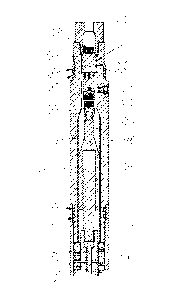
Referring to Figure 1, an electrical segment of the tool is shown according to
a first
embodiment of the tool and comprised of the electrical housing assembly (2)
defining an axial
hydraulic cavity (52) that can be filled with a hydraulic fluid (not shown)
for use in lubrication,
pressure compensation and viscous damping. The electrical housing (2) further
comprises a
means for sealed mechanical attachment to the tool string (60), shown in this
embodiment as
using a threaded joint and 0-ring (4) combination. Mounted within said
electrical housing (2) is
an electrical pressure feedthrough (5), containing a plurality of sealed
conductors (not shown)
and a means of sealing the electrical pressure feedthrough (5) to an inner
surface of the
electrical housing assembly (2), for example as shown Figure1, as 0-rings (3)
on the outer
diameter of the electrical housing assembly (2).
This electrical pressure feedthrough (5) forms a separation between the
interior of any tools on
the tool string (6) uphole of the present tool (38), and the hydraulic cavity
(52) of the tool (38)
below. An uphole end of the feedthrough (5) provides terminals (76) for
attachment of a
plurality of conductors for adaptation to any desired tool. Said feedthrough
(5) is held in place
by locking nut (1) as well as by the internal positive pressure of the
hydraulic fluid within the
hydraulic cavity (52) of said electrical housing (2). Also provided in said
electrical housing (2) is
a threaded pressure plug (6) sealed with an exterior 0-ring (7) provided as a
means of filling
and emptying the hydraulic cavity (52) of the tool (38) and providing a sealed
barrier between
the hydraulic chamber of the tool and the exterior environment.
An electrical connector (8) is connected to said feedthrough (5) and
operatively attached to a
retractile cable section (10). Said retractile cable section (10) sits in the
hydraulic fluid cavity
(52) of the tool (38), which is at least partially internally lined with a
protective sleeve (9),
mounted in an inner bore of said electrical housing (2). The retractile cable
section (10) is
connected to straight cable section (11). The straight cable section (11) is
clamped by cable
clamp (12) which is operatively connected to piloting shaft (13). The piloting
shaft (13) makes
up a terminal end of a shaft assembly (70) which is defined in more detail
below. The retractile
cable (10) serves as a means to accommodate a repeated change in the distance
between cable
clamp (12) and feedthrough (5) that is caused by vibration, without disruption
of the plurality of
E3036362 DOCX;1 E3030700.DOCX;1
E3025759.DOCX;1
CA 02944572 2016-10-07
9
conductor paths. Conductor paths can include any conductor paths contained in
the cables (10)
and (11) and running through the tool. The conductor paths can carry any type
of signal, or
power or other information from the downhole tool (39) to be isolated up
through the tool
string (60). Said electrical housing (2)15 operatively connected to a spring
housing (15) and
sealed by means of 0-rings (54).
Considering next Figure 2, the electrical segment of the tool is shown
according to a second
embodiment of the invention. It is comprised of the same components as the
first embodiment
of the invention shown in Figure 1, however in this embodiment, the retractile
cable section
(10) and cable clamp (12) is replaced with a linear sliding connector (33)
which is operatively
connected at an uphole end to the connector (8) and at a downhole end to the
piloting shaft
(13) and the straight cable section (11). The linear connector 33 is a
connector containing a
plurality of conductors which allows for continuous electrical connection
while allowing axial
movement due to vibration thus allowing for a change in distance between the
piloting shaft
(13) and the feedthrough (5) while maintaining connection along the plurality
of conductors.
Considering next Figure 3 and Figure 4, a spring segment of the tool is shown,
which can be part
of either embodiment of the electrical segment of Figures 1 and 2, but is
illustrated as a
continuation of Figure 1. The spring segment is comprised of a spring housing
(15) operatively
connected on a top end to said electrical housing (2) and operatively
connected on a bottom
end to torsional housing (20). An upper spring element (14), housed within
said spring housing
(15) and piloting on said piloting shaft (13) is clamped between said
electrical housing (2) and a
flange of said piloting shaft (13) providing a means for the piloting shaft
(13) to exert a force
through the spring (14) to vary the length between the electrical housing (2)
and the piloting
shaft (13). This creates a force path through the springs, said force path
being variable as the
shaft assembly (70) moves relative to the housing assembly (72).
A lower spring element (16) housed within said spring housing (15) and
piloting on said piloting
shaft (13) is clamped between the flange of said piloting shaft (13) and
spacer block (18) where
said spacer block (18) is itself operatively installed against the end face of
torsional housing (19)
E3036362.DOCX;1 E3030700.DOCX;1
E3025759.DOCX,1
CA 02944572 2016-10-07
thus providing a variable length force path between the piloting shaft (13)
and to exert a force
through the lower spring (16) to the torsional housing (20).
In the preferred embodiment of the invention, the stress profile of each of
the spring elements
(14, 16) at their limit of travel is within the infinite fatigue limit of the
material from which the
spring is made.
In the preferred embodiment of the invention the spring elements (14, 16) are
manufactured
with different dimensions and spring rates and in the presence of no
compressive or tensile
forces, will return the piloting shaft (13) to a biased position with respect
to the limits of travel.
In the preferred embodiment of the invention, the bias introduced by the
spring elements (14,
16) will be essentially equal and opposite to the bias introduced by the
expected "dead load" of
the tool to be isolated.
The upper and lower springs (14) and (16) work together to operatively
maintain the position of
the piloting shaft (13) when the tool is not subjected to vibrations. Further,
the piloting shaft
(13) contains an axial passage for the cable (11) as well as a plurality of
cross axis holes that
provide for movement of hydraulic fluid within the tool (38). Piloting shaft
(13) is operatively
connected to bearing shaft (17) that houses a retainer (43). A bearing nut
(19) and a plurality of
ball bearings (44) are moveably held between a plurality of axial raceways
(64) formed on the
bearing nut (19) and mating raceways (66) formed on the bearing shaft (17).
The spherical ball
bearings (44) transmit torque from the bearing shaft (17) to the bearing nut
(19) while being
able to roll axially along the raceway axis to provide axial motion with
little or no sliding friction.
In the preferred embodiment the bearing balls (44) are preloaded within the
bearing nut
raceways (64) to provide torsional rigidity with no backlash or lateral
movement. The ball
bearing (44) and raceway (64, 66) arrangement allows axial translation of the
bearing shaft (17)
in relation to the bearing nut (19) while preventing any relative rotational
movement of the
bearing nut (19) around the bearing shaft (17). The ball bearings and raceways
of the present
invention preferably operate within the general manner of linear spline
bearing assemblies.
E3036362.DOCX,1 E3030700.DOCX;1
E3025759.1DOCX;1
CA 02944572 2016-10-07
11
The bearing nut (19) is housed within a bore of the torsional housing (20) and
axially restrained
by means of a flange on the torsional housing (20) and the spacer block (18).
A key (21) or set
screw is used to prevent relative rotation between the torsional housing (20)
and the bearing
nut (19). However, it would be understood by a person of skill in the art that
the bearing nut
(19) could also be formed as an integral part of the torsional housing (20)
and also that the one
or more raceways (64) could be formed directly into the torsional housing (20)
without the
need for a bearing nut (19) at all.
The torsional housing (20) further provides a second threaded pressure plug
(6) and sealing 0-
ring (7) as a means for oil addition and removal from the lower portion of the
tool and a barrier
between the hydraulic cavity (52) of the tool (38) and the external
environment.
Considering next Figure 5, a compensation segment or compensation system is
shown as being
connected to a downhole end of the spring segment. The torsional housing (20)
of the spring
segment of the tool (38) is preferably operatively connected at a downhole end
to a
compensation housing (22). The compensation housing (22) of the compensation
system
comprises a shroud (78) having a plurality of holes (80) formed there in. The
shroud holes (80)
allow communication of any external fluid with an interior of the compensation
housing (22)
while the shroud (78) provides the interior components with protection from
the bulk external
fluid flow into the compensation housing. Also mounted to the lower end of the
torsional
housing (20) is a compensation membrane (24). Membrane (24) is flexible and is
operatively
connected to torsional housing (20) at a first end and to a membrane locking
shaft (25) a
second end, creating a fluid tight flexible joint between the housing assembly
(72) and the shaft
assembly (70).
In a preferred embodiment of the invention, attachment and sealing of the
compensation
membrane (24) is achieved by means of membrane clamp (23) and mating clamp
geometry on
torsional housing (20) and locking shaft (25). The compensation membrane (24)
is clamped, in
such a manner as to retain and form a fluid seal, separating fluids between
the compensation
membrane (24) and the bearing shaft (17) from fluids between the compensation
membrane
(24) and the compensation housing (22).
E3036362.DOCX,1 E3030700.DOCX;1
E3025759.DOCX,1
CA 02944572 2016-10-07
12
In a further preferred embodiment of the invention, the membrane (24) is made
from an
elastomeric material capable of withstanding the temperatures, pressures, and
chemicals
encountered during the drilling process and are provided with a plurality of
convolutions (74)
that allow its extension and contraction, within specified limits of travel.
In the preferred embodiment of the invention, the membrane (24) is designed to
permit a
specified volume of expansion and contraction in order to accommodate changes
in the
hydraulic fluid volume while maintaining the hydraulic fluid pressure at
essentially the same
pressure as the external fluid pressure.
While the compensation system is shown for use in the present anti-vibration
tool, the
inventors have found that the present compensation system can be used in any
linear actuator
or linear actuation device to provide both pressure compensation between an
external and an
internal fluid and to provide sealing of an internal segment of a linear
actuator from an external
segment. The unique combination achieving both sealing and pressure or volume
compensation by one system reduces the number of elements needed in typical
linear
actuation devices. In such cases, the torsional housing would be replaced by
the housing of any
linear actuator elements that make up the actuator housing uphole of the
compensation
system.
The bearing shaft (17) passes through the interior of the compensation
membrane (20) and is
operatively attached to the membrane locking shaft (25). A plurality of
openings are provided
through the wall of the torsional bearing shaft (17) for allowing hydraulic
fluid transfer between
the various segments of the tool (38). The cable (11) runs through the bores
of both the
torsional shaft (17) and the membrane locking shaft (25) and terminates in a
connector (8).
The compensation housing (22) is operatively connected on a downhole end to a
shaft limiting
nut (28). The nut (28) provides a solid flange on both the top and the bottom
for limiting the
travel of the shaft assembly (70) (to be described in further detail below) in
relation to the
=
housing assembly (72). The shaft limiting nut (28) is operatively connected on
its downhole end
to a protection sleeve (29), which is also fitted with a plurality of holes to
facilitate transfer of
the drilling fluid.
E3036362.DOCX,1 E3030700.DOCX,1 E3025759.DOCX;1
CA 02944572 2016-10-07
13
The membrane locking shaft (25)15 preferably fitted with a plurality of
bushings (26) and (27),
which engage with compensation housing (22) and shaft limiting nut (28)
respectively, and
provide lateral stability of the shaft assembly within the housing assembly.
The membrane
locking shaft (25) is operatively connected on the lower end to the lower
shaft coupler (31) and
sealed with 0-rings (32). The exterior of the lower shaft coupler (31) is
fitted with bushing (30)
which mates with the bore of the protection sleeve (29) to provide additional
lateral stability of
the shaft assembly. An electrical feedthrough (5) carrying a plurality of
sealed conductors and
operatively sealed on the outer diameter by 0-rings (3) is connected to
connector (8) and
mounted within the lower shaft coupler (31) and restrained in place by the
flange of the lower
shaft coupler (31) and the face of the membrane locking shaft (25) and marks
the end of the
conductor path through the tool (38) and the barrier between the hydraulic
cavity (52) and the
interior chamber of the downhole tool (39) to which the present tool (38) is
attached.
=
The remaining geometry of lower shaft coupler (31) and the electrical
connection to the bottom
end of electrical feedthrough (5) is not shown with these Figures but may be
customized or
configured to allow for compatible electromechanical attachment with any
downhole tool (39)
desired.
For the purposes of the present invention, the term housing assembly (72) is
considered to
include the electrical housing (2), the spring housing (15), the torsional
housing (20), the
compensation housing (22), the shaft limiting nut (28) and the protection
sleeve (29). The
elements of the housing assembly (72) remain fixed and do not move axially.
The term shaft assembly (70) is considered to include either of retractile
cable (10) or the linear
sliding connector (33) together with the piloting shaft (13), the bearing
shaft (17), the lower
shaft coupler (31) and the membrane locking shaft (25). The elements of the
shaft assembly
(70) move axially in response to vibrations in the drill string.
Preferably, all of the components of the present tool (38) are suitable for
operation at
temperatures up to 200C. Further preferably, all of the components of the
present downhole
tools are made of non-magnetic materials.
E3036362 DOCX;1 E3030700.DOCX;1 E3025759.DOCX,1
CA 02944572 2016-10-07
14
Operation:
In the preferred embodiment the tool (38) of the present invention is mounted
between the
portion (39) of the tool string (60) to be isolated and the portion (37) of
the tool string (60)
which is affixed to the drill string. Although the present tool (38) can be
configured for
mounting in various orientations, the assumption made for the purposes of this
description is
that the housing assembly (72), made up of components electrical housing (2),
the spring
housing (15), the torsional housing (20), the compensation housing (22), shaft
limiting nut (28),
and protection sleeve (29), is connected to the portion (37) of the tool
string (60) that is affixed
to the drill string. The shaft assembly (70), made up of components lower
shaft coupler (31),
membrane locking shaft (25), bearing shaft (17), piloting shaft (13), is
connected to the
remainder of the tool string (39) which is to be isolated.
When placed into operation, the external drilling fluid surrounds the tool at
high pressure and
high flow and exerts a force on the compensation membrane (24) which, in turn,
causes
pressure of the hydraulic fluid within the hydraulic fluid cavity (52) to rise
to the same pressure
as the external drilling fluid. This eliminates any tendency of the tool (38)
to compress due to
exterior fluid pressure.
When in the idle position, the opposing spring elements (16) and (14) maintain
a
predetermined neutral position of the shaft assembly (70) with respect to the
housing assembly
(72), the spring elements (16), (14) being configurable and configured to
provide a bias to
compensate for the effect of the tool string (60) dead load.
When the drill string is subject to vibration, the housing assembly (72) is
initially displaced some
axial distance, for example axially downhole or downwardly, with respect to
the shaft assembly
(70). As the housing assembly (72) moves relative to the shaft assembly (70),
the upper spring
element (14) is compressed against the electrical housing (2) and the flange
of the piloting shaft
(13) while the lower spring element (16) is allowed to extend thus creating a
downhole or
downward force on the shaft assembly (72). The decrease in distance between
the electrical
connections is accommodated by the retractile cable section (10) or the
sliding connector (33)
depending on the embodiment of the invention. The torsional shaft (17) is
allowed to translate
E3036362 DOCX;1 E3030700.DOCX,1
E3025759.DOCX,1
CA 02944572 2016-10-07
through the bearing nut (19) by rolling on the bearings (44) while being
restricted in rotation by
the raceways (64), (66), with minimal to no backlash, lateral movement or
frictional wear. The
compensation membrane (24) is compressed and the convolutions (74) grow in
amplitude in
order to accommodate relative motion between the shaft assembly (70) and the
housing
assembly (72), while maintaining integrity without the need for dynamic seals.
The hydraulic
fluid is permitted to re-distribute throughout the hydraulic cavity (52) of
the tool (38) via the
various openings and holes provided. The relative movement is allowed to
continue until such
time as the initial displacement reaches its maximum and begins to reverse or
the shaft limiting
nut (28) makes contact with the lower shaft coupler (31). At the point where
the housing
assembly (72) displacement reaches its maximum, the direction of displacement
is then
assumed to reverse and return to its original position. It is understood that
the system
generally functions in an equal but opposite analogous manner for uphole or
upwards initial
displacement of the housing assembly (72), with all relationships operating in
reverse.
Although the components herein have been described within the context of the
preferred
embodiments of the invention, it is should not be interpreted as being limited
solely to the
exact description as it is understood that minor alterations, substitutions or
modifications of
components, can be made by those skilled in the art without departing from the
intended
scope of the invention.
E3036362.DOCX,1 E3030700.DOCX;1
E3025759.DOCX;1