Note : Les descriptions sont présentées dans la langue officielle dans laquelle elles ont été soumises.
CA 02963613 2017-04-04
WO 2016/063212
PCT/IB2015/058064
1
SYSTEM FOR MONITORING AND CONTROLLING AN INDUSTRIAL PLANT
***
TEXT OF THE DESCRIPTION
Technical field
The present invention relates to systems for
monitoring and controlling an industrial plant, for
example for assembly and/or manufacture of structures
and/or components of motor vehicles.
The invention also regards systems that use the
information on production and status of the plant,
generated and made available by such industrial
production processes, for example for monitoring,
solving, and managing the errors and/or malfunctioning
of certain parts of the plant.
In greater detail, the present invention relates
to monitoring and control systems that comprise human-
machine interfaces, which enable an operator to display
the aforesaid information on production and status of
the plant and to generate and send commands for
management and control of the plant itself or portions
thereof.
Technical background
A scheme of an industrial plant 1 or assembly
line, for example for structures or components of motor
vehicles, of a known type is represented in Figures la,
lb, and lc.
In general, the plant 1 comprises a plurality of
processing and/or assembly stations ST, for example
cascaded to one another, where each station ST performs
a given operation, such as, for example, a machining
operation on a piece that it receives at input and/or
an assembly of pieces received. For instance, the plant
illustrated in Figure la envisages fifteen stations ST,
and at the end of the process the last station ST
CA 02963613 2017-04-04
WO 2016/063212
PCT/IB2015/058064
2
yields the semifinished piece.
In the example considered, the entire plant 1 is
divided into control areas A, such as four areas Al,
A2, A3 and A4.
As illustrated for example in Figure lb, each area
A comprises a subset of stations ST controlled by one
and the same fixed human-machine-interface (HMI) unit.
For instance, the first area Al may comprise the first
four stations ST1, ST2, ST3 and ST4. These stations are
monitored and controlled by the first fixed human-
machine-interface unit designated by the reference
HMIl.
Likewise, the area A2 may comprise the next four
stations controlled by the second fixed human-machine-
interface unit. In general, the number of stations ST
may even be different for the various control areas A.
Consequently, the first station ST1 can receive a
piece to be assembled and carry out its pre-set
intervention on the original piece for producing a
semifinished piece to be supplied at output. The
semifinished product at output from the station ST1 is
supplied at input to a second station ST2, where it is
received and clamped in position for the subsequent
process envisaged in the station ST2, etc.
Each station ST is typically equipped with at
least one actuator means and/or one sensor means for
carrying out and/or monitoring the operations performed
in that station. For instance, the operations that are
carried out in each station may be: assembly of some
additional parts, welding, control of the quality of
the welds, etc. There may also be envisaged stations
that perform exclusively a function of storage and/or
conveyance, such as, for example, the stations ST1,
ST6, ST11 and 5T15, which may for example be magazines
or conveyor belts.
CA 02963613 2017-04-04
WO 2016/063212
PCT/IB2015/058064
3
Usually, present in the aforesaid stations ST are
one or more industrial robots to render the operation
faster and of high quality. An industrial robot is an
automatically controlled, re-programmable, multi-
purpose manipulator, frequently used in applications of
industrial automation for carrying out manufacturing
processes. Hence, typically, the actuator means and
sensor means are on board said industrial robot and
enable execution and monitoring of the various
processing steps.
The piece remains in each station ST for the time
necessary for carrying out the process or operation
established for that given station. At the end of the
operation in one station, the piece is released and can
proceed along the path towards the next station of the
assembly line. For this purpose (see, for example,
Figure lc), typically each assembly station ST, for
example the stations 5T2-5T5, ST7-ST10 and ST12-5T14,
is equipped with actuator means AT1, Al2, AT3, ..., for
carrying out the process or processes associated to the
station and/or with sensor means Si, S2, S3, ..., for
acquisition of parameters on the status of the station.
As mentioned previously, each control area A is
typically equipped with a fixed human-machine-interface
unit HMI. For instance, the plant illustrated in Figure
la envisages four areas Al, A2, A3, and A4, and
consequently four fixed human-machine-interface units
HMI are provided. Typically, the fixed human-machine-
interface unit HMI is provided in an area adjacent to
the stations ST that the human-machine interface unit
HMI is able to monitor and/or control. In the example
illustrated, each fixed human-machine-interface unit
HMI monitors and controls the subset of stations of the
associated area A.
In particular, to control the stations ST, each
CA 02963613 2017-04-04
WO 2016/063212
PCT/IB2015/058064
4
fixed human-machine interface HMI is connected through
a communication network CON to an electronic control
and processing unit PLC, such as, for example, a
programmable-logic controller (PLC). For instance, as
illustrated in Figure lb, the interface HMI1 is
connected to the unit PLC1 through a communication
network COM1.
The electronic control and processing unit PLC is
in turn connected to the stations ST of the associated
area A, in particular (see Figure 1c) to the actuators
AT and to the sensors S of the associated stations ST.
For instance, for this purpose, a communication network
may be used, such as, for example, the network COM1
that is used for communication with the associated
interface HMI. For instance, the aforesaid
communication network may be an Ethernet, or a CAN
(Controller-Area Network) bus, or in general any wired
or wireless communication network.
Furthermore, the electronic control and processing
unit PLC is connected to a smart terminal of a SCADA
(Supervisory Control and Data Acquisition) type that
provides for remote monitoring of the entire assembly
line. For instance, for this purpose a communication
network may be used, such as, for example, the LAN
(Local-Area Network), for instance, an Ethernet,
preferably wired.
Currently, then, the function of global monitoring
lies in the SCADA smart terminal, whereas the local
functions of diagnostics, control, and intervention,
which are useful in the event of malfunctioning, are
managed directly by the fixed human-machine interface
HMI set in the vicinity of the assembly stations.
In general, one electronic control and processing
unit PLC may also manage the stations of a plurality of
areas A and hence interfaces HMI (see, for example,
CA 02963613 2017-04-04
WO 2016/063212
PCT/IB2015/058064
Figure 2), or vice versa a plurality of electronic
control and processing units PLC may be associated to a
single area A.
Consequently, in general, the plant described
5 previously, comprises a plurality of processing and/or
assembly stations ST, for example, for carrying out
operations on structures or components of motor
vehicles. One or more electronic control and processing
units PLC are associated to the assembly and/or
processing stations ST, for control of at least one
actuator AT and/or sensor S associated to the assembly
and/or processing station ST. Finally, at least one
human-machine-interface unit HMI is provided,
configured for monitoring or controlling the assembly
and/or processing stations ST through at least one
electronic control and processing unit PLC.
Typically, the SCADA smart devices are implemented
by means of one or more computers that are set outside
the site in which the assembly plant is located,
preferably in premises that are at a controlled
temperature and relatively clean. Consequently, the
aforesaid devices may even not be protected
specifically from humidity, dust, temperature jumps,
etc.
Instead, the fixed human-machine-interface units
HMI are positioned in the proximity of the assembly
stations and may be subject to critical working
conditions as regards humidity, dust, and temperature
jumps. Furthermore, in each plant a large number of
fixed human-machine-interface units HMI are required,
which contain a high level of built-in "intelligence"
and entail high costs for their installation and
maintenance.
With reference to Figure 3, in a plant 1 of a
known type the operator OP who wishes to intervene on a
CA 02963613 2017-04-04
WO 2016/063212
PCT/IB2015/058064
6
station ST must physically enter the area A in which
the station ST is contained and, through the fixed
human-machine-interface unit HMI associated to that A,
can control the station ST.
Instead, the terminal SCADA is exclusively a
monitoring terminal, from which the operator OP can
observe the entire assembly line, but if an
intervention is necessary, the operator OP must reach
the fixed human-machine-interface unit HMI associated
to the station ST to be controlled, and send directly,
via the aforesaid fixed human-machine interface HMI,
the command necessary for the station in question.
In particular, the fixed human-machine-interface
units HMI are located near the stations ST to enable an
operator OP to observe the effective status of the
plant and see in real time the effects resulting from
the modifications set via the command that he sends to
the station. In this way, the operator OP is able to
carry out, for example, an adjustment by varying the
input parameters and noting the behaviour at output,
thus carrying out a feedback control.
With the plants 1 of a known type the operator OP
has only two possibilities for monitoring a given
station ST, i.e., monitoring through the terminal SCADA
or physically entering the associated control area A
and querying the fixed human-machine-interface unit HMI
on the status of the station ST.
Object and summary
In the light of what has been set forth above, the
object of the present invention is to provide a system
for supervision and control of an industrial plant of
the type referred to previously that will enable a
convenient and versatile activity of monitoring and
control of the plant, thus overcoming one or more of
the drawbacks outlined above.
7
In one embodiment of the present invention there is provided
a system for monitoring and controlling an industrial plant (1)
comprising a plurality of assembly and processing stations (ST),
wherein said processing stations (ST) are associated to a
plurality of control areas (A), said system comprising: a
lurality of programmable-logic controllers (PLC), wherein
associated to each control area (A) is a respective at least one
programmable logic controller (PLC) for monitoring and/or
control of the processing stations (ST) that belong to the
respective control area (A); a communication network (LAN) that
connects said plurality of programmable-logic controllers (PLC)
together; at least one human-machine- interface unit configured
for monitoring and/or controlling said processing stations (ST),
wherein said at least one human-machine-interface unit comprises
a portable computer (TAB) having a wireless transceiver (12),
wherein said portable computer (TAB) is programmed (SRV) for
executing a plurality of functions, including global monitoring
of the industrial plant (1), local monitoring of at least one of
said processing stations (ST), and local control of at least one
of said processing stations (ST), wherein each portable computer
(TAB) comprises a device (10) having stored a code that uniquely
identifies the respective portable computer (TAB); means (AP, R,
SRV) configured for enabling access of said portable computer
(TAB) to said communication network (LAN) through said wireless
transceiver (12) in such a way that said portable computer (TAB)
can send monitoring and/or control commands to said respective
at least one programmable-logic controller (PLC); and a
plurality of identification devices (DK; AP), wherein associated
to each control area is a respective identification device (DK;
AP) for detecting the presence of said portable computer (TAB)
in a given control area (A), wherein, for detecting the control
area (A) in which said portable computer (TAB) is located, each
said identification device (DK; AP) comprises a reader (20)
configured for detecting the presence of said portable computer
(TAB) and reading the code that uniquely identifies the
CA 2963613 2022-03-02
7a
respective portable computer (TAB), wherein said system is
configured for executing a control command generated via said
portable computer (TAB) and addressed to a given processing
station (ST) only if said identification device (DK; AP) has
detected the presence of said portable computer (TAB) in the
control area (A) in which said given processing station (ST) is
located; characterized in that: said control command is an
instruction that comprises a field that identifies the portable
computer (TAB) that has send the control request, a field that
identifies the processing stations (ST) to which the command is
addressed and a field that contains the instruction; each
identification device (DK) has stored (20) within it a code that
uniquely identifies the respective identification device (DK)
and consequently the control area (A) associated to the
respective identification device (DK), wherein each
identification device (DK) is connected to said respective at
least one programmable-logic controller (PLC) and configured to
send said code that uniquely identifies the respective portable
computer (TAB) and said code that uniquely identifies the
respective identification device (DK) to the respective at least
one programmable-logic controller (PLC) signalling in this way
the control area (A) where said portable computer (TAB) is
located; and said plurality of programmable-logic controllers
(PLC) are configured for executing the control command generated
via said portable computer (TAB) and addressed to a given
processing station (ST) only if said portable computer (TAB) and
said given processing station (ST) are located in the same
control area (A).
In various embodiments, the human-machine interfaces
described previously can be replaced by a portable computer,
such as, for example, a mobile device, for example a computer of
the tablet type, programmed for executing a plurality of
functions, comprising global monitoring of the plant, local
monitoring of each individual station, and local control of one
of the stations.
CA 2963613 2022-03-02
7b
In particular, the electronic control and processing unit
associated to a given processing or assembly station authorizes
and executes a control command generated by a portable human-
machine-interface unit only if the electronic control and
processing unit detects the presence of the portable human-
machine-interface unit in the area close to the station.
The main advantage of the system for monitoring and
controlling an industrial plant according to the invention lies
in the fact that the human-machine-interface unit is portable
and enables monitoring of the plant and of the various assembly
stations to be carried out from any position inside or outside
the plant.
Furthermore, through management of user profiles, each
operator can select only the functions that are accessible to
him or her and has available additional functions, such as, for
example, display of tutorial images or videos, designed to
instruct the operator on one or more manual operations to be
performed in a given assembly station for solution of any
CA 2963613 2022-03-02
CA 02963613 2017-04-04
WO 2016/063212
PCT/IB2015/058064
8
malfunctioning. This renders the interventions of the
operator faster, better targeted, and more incisive.
For instance, to detect the presence of the
portable human-machine-interface unit in the vicinity
of the station, the system may comprise a plurality of
identification devices arranged in a substantially
predefined position and/or close to the assembly
stations. Each identification device is associated to a
given control area, which comprises one or more
assembly and/or processing stations for enabling
detection of the position of a portable human-machine-
interface unit in the area under control.
For instance, in this case, the identification
device can detect identification of a portable human-
machine-interface unit and can communicate with one or
more electronic control and processing units associated
to the same area to which the identification device is
associated for confirming the presence of the portable
human-machine-interface unit.
For instance, in a preferred embodiment, the
portable human-machine-interface unit is provided for
operating in wireless mode and for automatically
pairing with one of the identification devices when the
human-machine-interface unit is brought into the
proximity of the identification device. Pairing between
the portable interface unit and the identification
device can also activate the functions of command and
control of the assembly and/or processing stations
associated to the identification device with which the
tablet portable interface unit has carried out pairing.
Thanks to the aforesaid characteristics, the
system for monitoring and controlling an industrial
plant according to the invention has a high degree of
operating flexibility, being adaptable for operating in
different modalities and with the capacity to carry out
CA 02963613 2017-04-04
WO 2016/063212
PCT/IB2015/058064
9
a plurality of functions by means of a single device.
In particular, the system for monitoring and
controlling an industrial plant according to the
invention enables, via the portable unit, for example a
tablet, execution of a plurality of functions, such as
monitoring of the entire plant, diagnostics, and
immediate intervention in the event of malfunctioning
of a single assembly and/or processing station, and
access to databases available for training having
tutorial functions for the operator.
In particular, with the portable interface unit
according to the present invention it is possible to
carry out monitoring of the plant as a whole, this
being a function that before was available only via the
smart terminal of a SCADA type, which functioned as
sole remote control station.
It is moreover possible to monitor individual
assembly stations without the need to go directly to
the individual station to be monitored; i.e., it is for
example possible to monitor the first station even
though the portable interface unit is located at the
last station.
In addition, each operator can query through the
portable interface unit the databases to obtain in real
time the information on management and solution of
malfunctioning of a particular station, without
actually having to go to the SCADA smart terminal, as
was the case in the past.
Further characteristics and advantages of the
invention will emerge from the ensuing description.
Brief description of the drawings
One or more embodiments will now be described,
purely by way of non-limiting example, with reference
to the annexed drawings, wherein:
- Figures 1, 2, and 3, which regard the known art,
CA 02963613 2017-04-04
WO 2016/063212
PCT/1B2015/058064
have already been described previously;
- Figures 4a, 4b, 5a and 5b are schematic views of
some embodiments of a system of supervision and control
of an industrial plant according to the present
5 invention;
- Figure 6 is a block diagram that illustrates the
architecture of the system and the connections between
the elements that make it up;
- Figures 7 to 9 are further block diagrams that
10 illustrate the architecture of the system and the
connections between some of the elements that make it
up;
- Figure 10 is an example of tablet interface
unit; and
- Figures 11a-e] illustrate various screenfuls
associated to the various functions available on the
tablet interface unit.
It will be appreciated that, for greater clarity
of illustration, the parts visible in the figures are
not to be considered necessarily represented in scale.
Detailed description
Illustrated in the ensuing description are various
specific details aimed at providing an in-depth
understanding of examples of one or more embodiments.
The embodiments may be obtained without one or more of
the specific details, or with other methods,
components, materials, etc. In other cases, known
structures, materials, or operations are not
illustrated or described in detail so that various
aspects of the embodiments will not be obscured.
Reference to "an embodiment" or "one embodiment" in the
framework of the present description is intended to
indicate that a particular configuration, structure, or
characteristic described in relation to the embodiment
is comprised in at least one embodiment. Hence, phrases
CA 02963613 2017-04-04
WO 2016/063212
PCT/IB2015/058064
11
such as "in an embodiment" or "in one embodiment" that
may be present in various points of the present
description, do not necessarily refer to one and the
same embodiment. Furthermore, particular conformations,
structures, or characteristics may be combined in any
adequate way in one or more embodiments.
The references used herein are provided only for
convenience and hence do not define the sphere of
protection or the scope of the embodiments.
In the ensuing description parts that are the same
as the ones already described previously with reference
to the prior art will be designated by the same
references.
For instance, the reference number 1 designates as
a whole a production and/or assembly plant or line
comprising a plurality of fixed assembly and/or
processing stations ST. For instance, as illustrated in
Figure 4a the plant I may comprise fifteen stations ST,
and the last station ST yields the finished piece.
Also in this case, the plant is divided into
control areas A, such as, for example, four areas Al,
A2, A3, and A4, and each area A corresponds to a subset
of assembly stations adjacent to one another.
In general, the plant further comprises a system
for monitoring and control of the industrial plant 1
comprising at least one electronic control and
processing unit PLC, such as, for example, a
programmable-logic controller (PLC). In particular, as
described previously, these PLC units communicate with
the actuators AT and/or sensors S of the stations ST
for controlling and/or monitoring operation of the
stations ST (see Figure 4b).
In various embodiments, a respective electronic
control and processing unit PLC is associated to the
stations ST that belong to a given area A. For
CA 02963613 2017-04-04
WO 2016/063212
PCT/1B2015/058064
12
instance, as illustrated in Figure 4a, four units PLC1,
PLC2, PLC3, and PLC4 may be provided for the four areas
Al, A2, A3 and A4, respectively.
Instead, the number of the units PLC may also be
lower or higher than the number of the areas A. For
instance, in the embodiment illustrated in Figure 5a
only two units PLC1 and PLC2 are provided, which
control the stations ST. Instead, in the embodiment
illustrated in Figure 5b seven units PLC1, PLC7 are
provided, which control the stations ST. In particular,
a given PLC unit can also control stations ST that are
assigned to different areas A (see, for example, the
unit PLC6 of Figure 5b).
Consequently, in general, the system of
supervision and control of the plant 1 comprises one or
more electronic control and processing units PLC that
are associated to the assembly and/or processing
stations ST for controlling the actuators AT and/or
sensors S associated to the stations ST.
The architecture of the system moreover envisages
a human-machine-interface unit in the form of a
portable computer, such as, for example, a mobile
device or tablet, designated by the reference TAB. In
general, by "portable computer" is meant a computer of
a portable type comprising a processor, display means
for displaying information, a user interface, and an
electric-charge accumulator, such as, for example, a
battery. For instance, in the case where the processor
TAB is a tablet, the display means and the user
interface are implemented with a touchscreen.
As illustrated in Figure 4a, the portable computer
TAB further comprises a wireless-communication
interface that enables connection to the local network
LAN that connects the electronic control and processing
units PLC.
CA 02963613 2017-04-04
WO 2016/063212
PCT/1B2015/058064
13
For instance, as illustrated in Figures 4a and 6,
the network LAN may comprise one or more access points
AP, and the portable computer TAB may comprise a
corresponding wireless transceiver 12. In this case,
the communication between the portable computer TAB and
an access point AP is obtained via a wireless
communication, and the access point AP converts the
communication into the protocol used by the network
LAN. For instance the communication between the access
point AP and the electronic control and processing unit
PLC is preferably obtained via wired communication, for
example an Ethernet that may comprise one or more
switches.
For instance, communication between the portable
computer TAB and the access point AP may be based upon
the WiFi (Wireless Fidelity) protocol of the IEEE
802.11 standard. In particular, in the embodiment
considered in Figure 4a, the aforesaid wireless network
covers the entire production line 1. For instance, this
may be obtained via a plurality of access points AP
that have the same SSID (Service Set IDentifier) and/or
one or more radio-signal repeaters.
In general, the aforesaid communication network
that covers the entire line 1 could be obtained also
via a portable computer TAB that comprises a
communication interface of a mobile-radio network, such
as, for example, a GPRS (General Packet Radio Service)
modem, a UMTS (Universal Mobile Telecommunications
System) modem, an HSPA (High-Speed Packet Access)
modem, or an LTE (Long Term Evolution) modem, in which
the aforesaid interface connects up, via a mobile
communication protocol, designated in Figure 4a by the
reference 3G, to a base station BS for enabling a
communication with the Internet INET. In this case, the
system for control and monitoring of the plant 1 may
CA 02963613 2017-04-04
WO 2016/063212
PCT/1B2015/058064
14
comprise a router R, such as, for example, an ADSL
router or an optical-fibre router, which connects the
network LAN to the Internet INET and enables an
exchange of data with the portable computer TAB
exploiting communications through the Internet INET.
Preferably, the portable computer TAB has
installed on it an operating system, typically of the
multi-tasking type, which enables execution of a number
of applications simultaneously, such as, for example,
Windows Mobilem, IOSTM, or AndroidTM.
In an embodiment, the portable computer TAB
envisages an application that implements the functions
of global monitoring that before were obtained by the
smart terminal SCADA illustrated in Figures la, 2, and
3.
In an embodiment, an application also implements
the functions of local monitoring that were obtained by
the fixed human-machine interfaces HMI shown in Figures
la, 2, and 3.
Finally, in an embodiment, an application offers
the functions of display of tutorial images or videos
for immediate training of an operator OP. For instance,
the latter function may have the purpose of instructing
the operator OP on one or more manual operations to be
performed in a given station ST for solving a given
malfunctioning of the station ST.
In general, the above functions can be implemented
through a single application or distinct applications
that are installed on the portable device TAB.
As mentioned previously, the portable interface
unit TAB comprises display means and data-input
peripherals (for example, a touchscreen, which may also
show a keypad) and may envisage image-acquisition
means, such as a digital photographic camera, or audio-
acquisition means, such as a microphone for adding
CA 02963613 2017-04-04
WO 2016/063212
PCT/1B2015/058064
audio comments. An example of portable human-machine-
interface unit TAB is illustrated in Figure 10. In
particular, in the example illustrated, the portable
computer TAB is equipped with a protective case or
5 cover C made of rubber or silicone for protecting the
interface from any impact.
For instance, in various embodiments, the portable
interface unit TAB is configured for displaying on a
screen various icons each associated to a different
10 application or operating mode selectable via the
aforesaid data-input peripherals.
As illustrated in Figure 7, the control and
monitoring system may also comprise a central computer
SRV of a server type for providing services and data to
15 the portable computer TAB and/or the electronic control
and processing units PLC. In general, the functions of
the server SRV may be implemented via portions of
software code that are executed via a computer or a
processing system with distributed architecture (the
so-called "cloud computing").
For instance, operation of the portable device TAB
may be managed via the central server computer SRV. For
this reason, the application installed on the portable
computer TAB could even be just a display, and the
commands addressed to the electronic control/processing
unit PLC could be generated directly by the server SRV,
i.e., the server SRV could be a so-called "terminal
server", installed on which are all the control and
monitoring applications, and the portable computer may
have installed thereon a so-called "terminal client"
that is connected to the aforesaid terminal server SRV.
For instance, use of such a terminal server SRV is
advantageous if a number of portable terminals TAB are
envisaged, because it is sufficient to update just the
applications installed on the aforesaid server SRV.
CA 02963613 2017-04-04
WO 2016/063212
PCT/1B2015/058064
16
In one embodiment, the portable computer TAB
envisages an application that implements the functions
of global monitoring that before were carried out by
the smart terminal SCADA illustrated in Figures la, 2
and 3. In this case, the use of a terminal server SRV
renders management of global monitoring (of a SCADA
type) even more efficient, because a single computer
SRV can carry out periodic monitoring of the status of
the plant and receive possible notifications created by
the electronic control and processing units PLC. For
instance, these notifications may signal cases of
malfunctioning.
Consequently, in general the control and
monitoring function described herein can be obtained
via appropriate applications installed on the portable
device TAB and/or on the central server computer SRV.
Furthermore, in various embodiments, the portable
human-machine-interface unit TAB and/or the server SRV
is configured for managing different user profiles. In
general, management of these user profiles can be
implemented directly in the applications installed on
the portable device TAB. However, the user profiles are
preferably stored in the central server computer SRV.
For instance, the portable human-machine-interface
unit TAB can recognize the user profile of the operator
OP through a LOGIN operation. Next, through an
operation of authentication with the central computer
SRV, the portable interface TAB sets, on the basis of
the user profile returned by the central computer SRV,
a predefined configuration in terms of functions and
level of accessibility associated to the user profile
recognized. For instance, not all the operators OP can
have access to the function of global control and/or
monitoring. Furthermore, certain operators OP may have
access only to the functions of control and monitoring
CA 02963613 2017-04-04
WO 2016/063212
PCT/1B2015/058064
17
of a given control area A.
Illustrated in Figures ha to lie are some of the
possible configurations that may be accessed via the
portable interface TAB. For instance, in the embodiment
considered, it is possible to select a general
screenful for plant-level monitoring (Figure 11a), a
general screenful for plant production (Figure 11b), a
general screenful of the tutorials pages with
selectable predefined icons (Figure 11c), a screenful
for global monitoring (of a SCADA type) or local
monitoring (of a fixed HMI type), and finally a
screenful for managing documents or videos (Figure
11e).
In various embodiments, the monitoring and control
system is configured for carrying out local control of
a processing and/or assembly station ST if and only if
the human-machine-interface unit TAB is in the vicinity
of the respective station ST, in particular when the
human-machine-interface unit TAB is located in the
control area A associated to that station ST.
In general, the system comprises for this purpose
a positioning system that enables detection of the
position of the portable device TAB within the areas A.
In particular, in various embodiments, the
position of the portable computer TAB is detected via
an operation of pairing with an identification element.
For instance, in the embodiment illustrated in
Figure 4a and 4b, associated to each one of the areas A
into which the entire plant 1 is divided, is an
identification element DK. For instance, for a plant
with four control areas Al, A2, A3, A4 four presence
sensors DK1, DK2, DK3, DK4 are hence provided.
In particular, each identification element DK is
set in a substantially predefined position and/or a
position close to the respective subset of stations ST
CA 02963613 2017-04-04
WO 2016/063212
PCT/1B2015/058064
18
and enables detection of the presence of the portable
human-machine-interface unit TAB in an area A. For
instance, typically the aforesaid identification
elements DK are provided in the position where the
fixed human-machine interface HMI was normally
provided.
In general, the pairing operation between the
processor TAB and an identification element DK may be
carried out via a unidirectional or bidirectional
communication, and the communication may be wired or
wireless.
Consequently, for the human-machine-interface unit
TAB to be enabled for control of a station ST comprised
in a given area A, it must first execute a pairing
operation with one of the identification elements DK.
After the portable human-machine-interface unit
TAB has carried out pairing with the corresponding
identification element DK, the electronic control and
processing unit PLC associated to the assembly station
ST (and/or the server SRV) can authorize and execute
the control commands generated by the portable human-
machine-interface unit TAB.
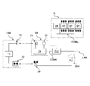
Figure 6 illustrates a first embodiment of the
monitoring and control system.
As explained previously, the portable human-
machine-interface unit TAB is pre-arranged for being
connected in wireless mode to the network LAN that
connects the electronic control and processing units
PLC. For instance, as explained previously, the
portable computer TAB can connect up to the network LAN
and/or to the server (which can operate as gateway or
application server) through a transceiver 12 that
communicates with at least one access point AP.
However, in general, it is sufficient for the processor
TAB to be able to send directly or indirectly (for
CA 02963613 2017-04-04
WO 2016/063212
PCT/1B2015/058064
19
example, via the server SRV) monitoring and/or control
instructions to the electronic control and processing
units PLC for requesting monitoring and/or control of a
given station ST associated to the respective
electronic control and processing unit PLC.
For instance, in various embodiments, the
positioning system that enables the position of the
portable computer TAB to be established is obtained via
a wireless-communication system.
For example, in the embodiment considered, the
human-machine-interface unit TAB comprises a
transceiver 10, and the identification element DK
comprises a transceiver 20.
As illustrated in Figure 6, for carrying out the
pairing operation, the aforesaid transceivers 10 and 20
can be connected to respective control units 14 and 24,
such as microprocessors, provided in the portable
computer TAB and in the identification element DK,
respectively.
In various embodiments, in particular in the case
where the fixed human-machine interfaces (for example,
the interfaces HMI in Figure 1) are no longer
envisaged, the device DK may moreover be equipped with
an emergency push-button 22 for blocking the respective
area A in the case of danger for an operator.
Furthermore, the aforesaid emergency push-button 22 can
also be provided on the portable interface TAB.
In various embodiments, the portable computer TAB
and the identification element DK are thus configured
for operating in wireless mode and for automatically
carrying out pairing when the portable interface unit
TAB is brought into the proximity of one of the devices
DK.
For instance, in one embodiment, pairing is
obtained by means of a short-range communication
CA 02963613 2017-04-04
WO 2016/063212
PCT/IB2015/058064
protocol, for example through an NFC (Near-Field
Communication), which is a technology that provides
bidirectional wireless (RF) connectivity between two
devices.
5 In general, a unidirectional communication between
the identification element DK and the portable computer
TAB may also be used.
For instance, one of the devices 10 or 20 may be
obtained via an RFID (Radio Frequency IDentification)
10 tag, on which some data are stored, and the other
device, 20 or 10 respectively, may be an RFID reader.
In this case, when the portable interface unit TAB is
brought into the range of action of the device DK, the
RFID tag responds to the remote query from the RFID
15 reader.
Furthermore, instead of the above wireless-
communication system, other types of tags can also be
used. For instance, one of the devices 10 or 20 can be
replaced with a tag with a barcode identifier or a code
20 of a two-dimensional type, for example a QR code, and
the other device, 20 or 10 respectively, may be a video
camera or a barcode reader.
Finally, in one embodiment, the human-machine-
interface unit TAB may be set physically in contact
with a terminal provided in the device DK designed to
receive and support the human-machine-interface unit
TAB to carry out pairing of the two devices.
Consequently, in general, communication between the
human-machine-interface unit TAB and the identification
device DK1 may be wired.
Consequently, irrespective of whether the
communication between the element 10 and the element 20
is unidirectional or bidirectional, one of the elements
10 or 20 stores a code and the other of the elements 10
and 20 is a reader that reads the code. Consequently,
CA 02963613 2017-04-04
WO 2016/063212
PCT/1B2015/058064
21
the aforesaid code may be a code that uniquely
identifies a portable device TAB or an identification
element DK.
In various embodiments, the device DK is moreover
connected to at least one electronic control and
processing unit PLC and/or the server SRV. For
instance, the device DK may be connected to an
electronic control and processing unit PLC via the
communication network CON that is used for
communication between the electronic control and
processing units PLC and the associated stations ST
(designated by COMa in Figure 6), or else an additional
communication network (designated by COMb in Figure 6)
may be used, which connects the device DK directly to
at least one electronic control and processing unit
PLC. Furthermore, the devices DK may also be connected
to the network LAN.
For instance, in a first embodiment, the
identification device DK periodically monitors the
presence of portable computers TAB in its vicinity and,
when the presence of a portable device TAB is detected,
the device DK reads the code that is associated to the
portable device TAB and that uniquely identifies a
given portable device TAB, referred to hereinafter as
TAB ID.
Next, the identification device DK sends the
aforesaid code TAB ID with its own identifier, referred
to hereinafter as DK ID, to the respective electronic
control and processing unit PLC and/or to the server
SRV, signalling in this way the position of the
portable device TAB, i.e., the control area A where the
portable device TAB is located. In fact, the identifier
DK ID identifies not only a given device DK but also a
given control area A.
In this case, when the respective portable device
CA 02963613 2017-04-04
WO 2016/063212
PCT/IB2015/058064
22
TAB requests control of a given station ST associated
to a given area A, the electronic control and
processing unit PLC associated to that station ST
and/or the server SRV can enable or inhibit control of
the station ST according to the position detected. In
this way, the portable device TAB can control only
stations ST that are associated to one and the same
area A.
For instance, typically a control command is an
instruction that comprises a field that identifies the
interface unit TAB that sends the control request, a
field that identifies the station ST to which the
command is addressed, i.e., a code that identifies a
given actuator AT of a station ST, and a field that
contains the instruction proper. In this case, the
server SRV may not send the control command to the
electronic control and processing unit PLC associated
to the station ST if the portable device TAB is not
located in the same area A, and/or the electronic
control and processing unit PLC associated to the
station ST may not execute the command if an
instruction is received from a portable computer TAB
that is not located in the same area.
Instead, as mentioned previously, in various
embodiments, the local and global monitoring function
can work in all cases.
Instead, in the case where the portable computer
TAB is configured for detecting the devices DK in its
vicinity, the portable computer TAB reads the code
DK ID associated to the device DK, which in turn
identifies a given area. In particular, preferably a
short-range communication (i.e., of just a few metres)
is used for pairing the portable device TAB with the
identification device DK, and consequently the portable
device TAB can detect only one device DK at a time.
CA 02963613 2017-04-04
WO 2016/063212
PCT/IB2015/058064
23
In this case, the portable computer TAB can
include in a control command, not only the identifier
of the station ST to be controlled, but also the
identifier DK ID of the identification device to which
the portable computer TAB is paired.
Consequently, also in this case the electronic
control and processing unit PLC associated to the
aforesaid station ST and/or the server SRV can enable
or inhibit control of the station ST according to the
position detected, and the portable device TAB can
control only stations ST that are associated to the
same area A. For instance, the server SRV may not send
a control command to the electronic control and
processing unit PLC associated to the station ST (or
the electronic control and processing unit PLC
associated to the station ST may not execute the
command) if the station ST to be controlled is not
located in the associated area A identified via the
code DK ID.
In general, the pairing operation could also
directly affect functioning of the applications
installed on the portable device TAB or managed via the
server SRV; for example, it could activate, on the
portable interface unit TAB, the functions of command
and control only for the stations ST that are
associated to the control area A to which the portable
interface unit TAB is connected up.
Consequently, in the control and monitoring
systems described, the interface unit TAB is programmed
for carrying out a plurality of functions, such as:
- a "high-profile" interface function, in co-
operation with the electronic control and processing
units PLC for global monitoring of the plant;
- a "low-profile" interface function, in co-
operation with an electronic control and processing
CA 02963613 2017-04-04
WO 2016/063212
PCT/IB2015/058064
24
unit PLC for monitoring and control of the processing
and/or assembly stations ST associated to a given
control area A; and
- a function for display of tutorial images or
videos for an operator, designed to instruct the
operator on one or more manual operations to be
performed in a given assembly station for solving a
case of malfunctioning.
In the embodiments described previously two
distinct communication channels are provided: a first
communication channel (for example, the RFID
communication channel in Figure 5a) for detection of
the position of the portable computer TAB; and a second
communication channel (for example, the WiFi
communication channel in Figure 5a) for sending
monitoring and control commands. In fact, in this case,
the portable interface unit TAB connects up, for
example via an access point AP and possibly the server
SRV, to the second network LAN for communicating with
the electronic control and processing units PLC.
Instead, the first network RFID is used for pairing
with an identification device DK, which has the purpose
of detecting the position of the portable computer TAB
within one of the control areas A. In this case, the
exchange of commands for control and monitoring of the
stations ST between the portable interface TAB and the
electronic control/processing unit PLC is obtained only
through the network LAN.
In general, these two communications may even be
made over one and the same communication channel.
For instance, as illustrated in Figure 8, the
identification device DK may be replaced with a
transceiver, such as for example an access point AP,
such as a WiFi access point. Consequently, in this
case, a transceiver AP is associated to each area A
CA 02963613 2017-04-04
WO 2016/063212
PCT/IB2015/058064
into which the entire plant 1 is divided. For instance,
for a plant with four control areas Al, A2, A3 and A4
four transceivers or access points AP1, AP2, AP3, AP4
are thus envisaged. In this case, communication between
5 the portable computer TAB and an access point AP is
made via a wireless communication, and the access point
AP converts the communication into the protocol used
for the network LAN.
Consequently, as compared to the embodiments
10 described previously, the access points AP are now in a
substantially fixed position, and a respective access
point AP is assigned to each control area A.
Furthermore, in the embodiment considered,
connection to a given access point AP replaces pairing
15 with the identification device DK, i.e., the access
point AP now also represents the identification device
DK that serves for detection of the position of the
portable computer TAB.
For instance, the portable computer TAB may
20 include in the request for control a field with a code
that identifies the access point to which the portable
computer TAB is connected, such as, for example, the
MAC address and/or the SSID of the access point AP. In
this case, the server SRV may not send a control
25 command, and/or the electronic control and processing
unit PLC may not execute the command if the controlled
station ST is not located in the area A assigned to the
respective access point AP.
In one embodiment, the server SRV or the
electronic control and processing unit PLC can also
detect the identifier of the access point AP to which a
given portable computer TAB is associated. For
instance, in one embodiment, the access point AP is
configured as router with NAT (network address
translation), and consequently the access point AP
CA 02963613 2017-04-04
WO 2016/063212
PCT/IB2015/058064
26
replaces the IP address of the processor TAB with its
own IP address. Consequently, the server SRV could
send, or else the electronic control and processing
unit PLC could execute, control commands only if these
commands come from a given IP address. In a similar
way, another element identifying the access point could
also be used, such as, for example, its MAC address.
Furthermore, in various embodiments, each access
point AP could assign to the portable computers TAB an
IP address taken from a certain range of non-
overlapping IP addresses. In this way, also the IP
address of the portable computer TAB can directly
identify the area A in which the portable computer TAB
is located.
Finally, Figure 9 shows an embodiment of a
mechanism for blocking the commands that uses a
firewall FW. The aforesaid firewall may be an
additional hardware element or be implemented via
software code, for example, in the server SRV.
In the embodiment considered, the network LAN is
divided into sub-networks, where one sub-network is
provided for each control area A.
Furthermore, provided for each sub-network are at
least one electronic control and processing unit PLC
that controls the stations ST assigned to the
respective area A and one access point AP. For
instance, four areas Al, A2, A3, and A4 are illustrated
in the embodiment, and consequently four sub-networks
LAN1, LAN2, LAN3, and LAN4 and four access points AP1,
AP2, AP3, and AP4 are provided.
In various embodiments, each sub-network has a
different range of IP addresses, for example
192.168.1.X for the network LAN1, 192.168.2.X for the
network LAN2, 192.168.3.X for the network LAN3, and
192.168.4.X for the network LAN4.
CA 02963613 2017-04-04
WO 2016/063212
PCT/IB2015/058064
27
Consequently, a portable computer TAB that
connects up to a given access point has access only to
the respective sub-network assigned to the respective
access point, for example the network LAN1 for the
access point AP1. Consequently, in one embodiment, the
portable computer TAB can send and execute freely
monitoring and control instructions in the respective
sub-network.
In general, each electronic control and processing
unit PLC and/or the server SRV could hence be
configured for enabling control only of stations that
are located in the control area A associated to the
sub-network, located in which is the portable computer
TAB, and inhibiting execution of control commands that
come from portable computers TAB that are located in
other sub-networks.
Instead, in the embodiment considered, the control
commands are blocked via a firewall FW that connects
the sub-networks LAN1, LAN2, LAN3, and LAN4 together.
In particular, this firewall FW is configured for
letting through monitoring commands, but blocking
sending of control commands between the sub-networks.
For instance, this can be obtained via filtering at a
protocol level, or by assigning to the control
communications a port different from that for the
monitoring communications and blocking the port
assigned to the control communications.
Consequently, in this embodiment, the portable
computer TAB can select the access point AP and hence
the network that should be controlled.
This embodiment presents the disadvantage that a
WiFi wireless network may have a wide coverage (some
tens of metres), whereas for the communication between
the identification element and the portable computer
TAB a short-range communication (for example between 1
CA 02963613 2017-04-04
WO 2016/063212
PCT/IB2015/058064
28
and 5 m) may be used. Consequently, the portable
computer TAB could also connect up to remote access
points.
In one embodiment, to overcome the above problem,
the transmission power of the access points could be
reduced, thus limiting coverage of the access point. In
addition, in one embodiment, the portable computer TAB
could be configured for connecting up automatically to
the access point with the highest transmission power,
which should hence correspond to the nearest access
point.
The general architecture of the system according
to the invention is altogether flexible, and enables
optimization of global and local monitoring via the use
of a portable terminal TAB with additional functions.
Furthermore, the possibility of exploiting
contents such as tutorial videos directly on the spot
enables the operator OP to learn the operations to be
performed, to execute them in real time, and to control
directly the reaction of the stations ST, thus speeding
up and optimizing interventions following upon any
malfunctioning.
Of course, without prejudice to the principle of
the invention, the details of construction and the
embodiments may vary widely with respect to what has
been described and illustrated herein purely by way of
example, without thereby departing from the scope of
the present invention.