Note : Les descriptions sont présentées dans la langue officielle dans laquelle elles ont été soumises.
CA 02963614 2017-04-04
1
Trolley for lifting gear
Description
The invention relates to a trolley for lifting gear, comprising a lifting
mechanism
arranged on a support frame and comprising running wheels which are mounted on
the support frame and via which the trolley can be moved on a beam and of
which at
least one first running wheel is mounted on an axle and the axle can be driven
together with the running wheel by means of a drive motor.
German laid-open document DE 103 45 102 Al discloses a trolley of a crane
which
can be moved via a total of four running wheels on and along a beam. The
running
wheels are typically arranged, as seen from above onto the beam, in the
corners of a
notional rectangle. One of the four running wheels is electrically driven. In
order to
transmit the drive forces of the driven running wheel in a reliable manner to
the beam
which also serves as a travel rail, a pair of resiliently biased friction
rollers are
provided, via which the driven running wheel is pulled onto the travel rail.
As an
alternative, it is described therein that a plurality of the running wheels
can be driven
via the one traction drive or in each case separate traction drives.
German laid-open document DE 1 803 471 A discloses a crane, on the delivery
carriage of which a trolley which is driven by means of a linear motor can be
moved.
The moving part of the linear motor comprises a traction mechanism which is
designed as a belt or chain and is driven by the stationary part of the linear
motor
formed by induction coils. The traction mechanism of the linear motor drives
two
wheel axles together with running wheels arranged at both ends on each wheel
axle.
The traction mechanism is part of the linear motor and is drivingly connected
upstream of the two wheel axles, so that both wheel axles are driven together
by the
traction mechanism.
FR 1 360 309 A describes a traction drive for the crane girder of a bridge
crane whose
running wheels are drivingly connected by means of a chain-like traction
mechanism.
Moreover, German laid-open document DE 10 2010 041 894 Al discloses a delivery
apparatus comprising a trolley whose traction drive has a belt drive.
CA 02963614 2017-04-04
2
The object of the present invention is to provide a trolley of a crane which
ensures a
reliable transmission of the drive forces between the running wheel and the
travel rail.
The object is achieved by a trolley of a crane comprising the features of
claim 1.
Advantageous embodiments of the invention are described in claims 2 to 9.
In accordance with the invention, in the case of a trolley for lifting gear,
comprising a
lifting mechanism arranged on a support frame and comprising running wheels
which
are mounted on the support frame and via which the trolley can be moved on a
beam
and of which at least one first running wheel is mounted on an axle and the
axle can
be driven together with the running wheel by means of a drive motor, a
reliable
transmission of the drive forces between the running wheel and the travel rail
is
ensured by virtue of the fact that the drivable first running wheel is
drivingly connected
to at least one of the further running wheels via a traction mechanism such
that the
axle is arranged between the drive motor and the traction mechanism and thus
the
traction mechanism is drivingly connected downstream of the axle, so that the
traction
mechanism can be driven by the axle. This embodiment has a simple structural
design and, in the case of relatively large spaced intervals between the
running
wheels, also renders it possible to drivingly connect said wheels in a simple
manner
and to transmit the corresponding drive forces. The traction mechanism, when
designed in a frictionally engaged manner, also prevents any overloading of
the
running gear unit because the running gear unit will simply slip when
overloaded. By
driving the trolley by means of at least two running wheels, the drive forces
are
transmitted more reliably to the travel rail. Therefore, a uniform movement of
the
trolley can be achieved even in rough operating situations. Slipping of the
running
wheels and therefore wear thereof are also minimised. Furthermore, the
traction
mechanism increases the smooth running of the driven running wheels.
In structural terms, it is particularly simple to use the traction mechanism
if the driven
first running wheel and the at least one of the further running wheels are
arranged, as
seen in the direction of travel of the trolley, one behind the other and on a
common
side of the beam.
Preferably, provision is made that the second running wheel can be driven by
the
CA 02963614 2017-04-04
3
driven first running wheel via the traction mechanism. As a result, sufficient
traction is
achieved for the majority of operating scenarios.
In a preferred embodiment, the traction mechanism is designed as a V-ribbed
belt.
The V-ribbed belt allows the drive forces to be transmitted in a reliable
manner and
with almost no slip.
In structural terms, provision is made that in each case a traction mechanism
disk is
drivingly allocated to the driven running wheels and the traction mechanism
rotates
about the traction mechanism disks.
A particularly compact and simple design is achieved by virtue of the fact
that the
driven running wheels and the associated traction mechanism disk are formed in
each
case in one piece. In this case, it is particularly advantageous that the
traction
mechanism disk adjoins a respective running surface of the driven running
wheels.
In an alternative embodiment, provision is made that the driven running wheels
and
the associated traction mechanism disk are drivingly connected to one another
in
each case by means of a motor shaft or an axle. The traction mechanism thus
extends on the rear side of the first longitudinal beam and thus on the side
thereof
facing away from the beam. As a result, the traction mechanism drive is
protected
against any possible soiling caused by the movement of the trolley on the
beam.
In order to increase the traction of the driven running wheels, said wheels
are acted
upon via resiliently biased friction rollers in the direction of the beam
serving as the
travel rail.
The invention will be explained in greater detail hereinafter with reference
to several
exemplified embodiments which are illustrated in the drawing, in which:
Figure 1 shows a perspective view of a trolley of a crane,
Figure 2 shows a plan view of the trolley shown in figure 1 but without a
traction
mechanism,
Figure 3 shows a front view of the trolley shown in figure 1,
Figure 4 shows a detailed view of the trolley shown in figure 1,
CA 02963614 2017-04-04
4
Figure 5a shows a sectional view of a driving running wheel,
Figure 5b shows a sectional view of a driven running wheel,
Figure 6 shows a perspective view of a trolley of a crane in a second
embodiment,
and
Figure 7 shows a perspective view of a trolley in a third embodiment for
lifting gear
designed as a chain hoist.
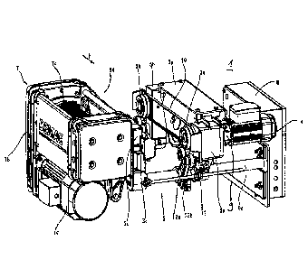
Figure 1 shows a perspective view of a trolley 1 of a bridge crane, not
illustrated. For
reasons of clarity, a beam 2 (see figure 3), which typically extends
horizontally and on
which the trolley moves, and a load hook are not illustrated. The trolley 1
can be
moved along the beam 2, in particular in the longitudinal direction thereof,
via a total
of four running wheels 3a, 3b, 3c and 3d each having an identical diameter.
The
running wheels 3a, 3b, 3c and 3d are typically arranged, as seen from above
onto the
beam 2, in the corners of a notional rectangle (see also figure 2). Of the
four running
wheels 3a, 3b, 3c and 3d, a first running wheel 3a and a second running wheel
3b are
driven together by means of an electric drive motor 4. As seen in the
direction of
travel F of the trolley 1 and thus in the longitudinal direction of the beam
2, the first
running wheel 3a and the second running wheel 3b are arranged at a spaced
interval
with respect to one another and one behind the other. The third and fourth
running
wheels 3c and 3d which are opposite the first and second running wheels 3a and
3b
respectively are not driven and are freely rotatable. All of the running
wheels 3a, 3b,
3c and 3d are mounted on a support frame 5 of the trolley 1 so as to be able
to rotate
about horizontal and mutually parallel or mutually aligned axes. The axes
extend
horizontally under the assumption that the running surfaces of the beam 2
extend
horizontally.
The intrinsically bending-resistant support frame 5 of the trolley 1 is
composed of a
plurality of components which will be explained in greater detail hereinafter.
As seen
in the direction of travel F of the trolley 1 and thus in the longitudinal
direction of the
beam 2, the support frame 5 is formed in a u-shaped manner. In order to mount
the
four running wheels 3a, 3b, 3c and 3d in the manner of a vehicle, the support
frame 5
has four cuboidal bearing brackets 5a, 5b, 5c and 5d, of which in each case
the first
and third bearing brackets 5a and 5c which are opposite in relation to the
beam 2 are
interconnected at their lower ends to a first transverse beam 6a and the
opposite
second and fourth bearing _brackets 5b and 5d are connected at their lower
ends to a
CA 02963614 2017-04-04
second transverse beam 6b (see figure 2). The two u-shaped front and rear
bearing
parts thus produced are then connected via first and second longitudinal beams
5e
and 5f, which extend in the direction of travel F of the trolley 1, to form
the support
frame 5. In this case, the first longitudinal beam 5e connects the first and
second
bearing brackets 5a and 5b and the second longitudinal beam 5f connects the
third
and fourth bearing brackets 5c and 5d. In the present exemplified embodiment,
a
lifting mechanism 7 which is arranged on the support frame 5 of the trolley 1
assumes
the function of the second longitudinal beam 5f. The first and second
transverse
beams 6a and 6b are designed as pipes, on which the first and second bearing
brackets 5a and 5b can be displaced and fixed, in order to adapt the trolley 1
to the
width of the beam 2 and mount it thereon.
Furthermore, it is evident in figure 1 that the first running wheel 3a mounted
on the
first bearing bracket 5a is driven by an electric drive motor 4 which is
flange-mounted
on the end of the first bearing bracket 5a opposite the first running wheel 3a
via a
travel gear mechanism 9. The axes of rotation of the travel motor 4 and of the
first
running wheel 3a extend in parallel with one another or are aligned with one
another.
The lifting mechanism 7 which can be moved by means of the trolley 1 in the
direction
of travel F thereof and thus in the longitudinal direction of the beam 2
typically
consists of an electric lifting motor 7a which acts upon a cable drum 7c via a
lifting
gear mechanism and is designed preferably as a cable winch. On the whole, the
lifting mechanism 7 has a compact c-shaped form. In this case, the lifting
motor 7a is
arranged below the cable drum 7c, wherein the axes of rotation thereof extend
in
parallel and in the direction of travel F. The lifting gear mechanism 7b
connects the
lifting motor 7a and the cable drum 7c to one another at a rear end as seen in
the
direction of travel F. If the beam 2 is e.g. part of a bridge crane, the beam
2 can be
moved transversely with respect to its longitudinal extension by means of
traction
drives arranged at both ends on the beam 2. As a result, the trolley 1 with
the lifting
mechanism 7 arranged thereon can then also be additionally moved transversely
with
respect to the longitudinal direction of the beam 2. Therefore, a movement of
the
lifting mechanism in the longitudinal direction of the beam 2 by means of the
trolley 1
is independent of any additionally possible movement transversely with respect
to the
longitudinal direction of the beam 2 by means of the possible traction drives
for the
beam 2.
CA 02963614 2017-04-04
6
In order to drive not only the first running wheel 3a but also the second
running wheel
3b, the first running wheel 3a and the second running wheel 3b are driving
connected
to one another by means of a traction mechanism 10. The traction mechanism 10
is
guided circumferentially around a first traction mechanism disk lla and a
second
traction mechanism disk llb which are each allocated to the first and second
running
wheels 3a and 3b and have the same effective diameter. In other words, the
traction
mechanism 10 is arranged outside of the travel motor 4 and therefore is
drivingly
connected downstream of the travel motor 4 and the axle, on which the driven
first
running wheel 3a is mounted, so that the traction mechanism 10 is driven by
the
corresponding axle. Therefore, the traction mechanism 10 does not drive the
axle of
the first running wheel 3a but rather is driven thereby. Therefore, by means
of the
driving connection, the traction mechanism 10 only drives the axle on which
the
second running wheel 3b is mounted. The first and second traction mechanism
disks
11 a and 11 b can be mounted on the axles of the first and second running
wheels 3a
and 3b and therefore can be arranged adjacent to the running wheels 3a and 3b
or
remote therefrom or can be fastened directly to the first and the second
running
wheels 3a and 3b. In the illustrated exemplified embodiment, the first and
second
traction mechanism disks lla and llb are each an integral component of the
first and
second running wheels 3a and 3b respectively. The traction mechanism 10 is
designed preferably as a V-ribbed belt and the first and second traction
mechanism
disks 11a and llb are designed correspondingly as profiled V-ribbed belt
disks. It is
also feasible to use, as the traction mechanism 10, form-fitting traction
mechanisms
such as toothed belts and roller chains or frictionally engaged traction
mechanisms
such as V-belts, flat belts and circular belts. The first and second traction
mechanism
disks lla and llb are then designed in a complementary manner with respect to
the
traction mechanism 10 selected in each case.
The first and second transverse beams 6a and 6b are also extended beyond the
first
and third bearing brackets 5a and 5c, in order to accommodate, at their end
opposite
the lifting mechanism 7, an electric connection box 8.
Figure 1 shows a trolley which is designed as a so-called monorail trolley
having a low
installation height. This design is characterised by its compact and space-
saving
construction. In this case, the lifting mechanism 7 is arranged laterally next
to the
CA 02963614 2017-04-04
7
beam 2 as seen in the direction of travel F, so that the load hook 13 (see
figure 3) can
be raised as high as possible underneath the beam 2. This causes, in relation
to the
centre of the beam 2, a lateral shift of the centre of mass of the lifting
mechanism 7.
As a result, when the trolley 1 is moving without a payload there is the risk
that the
driven first and second running wheels 3a and 3b which are opposite the
lifting
mechanism 7 will be relieved of loading, lift off and/or slip. A comparable
operating
situation can result from an oscillating load suspended from the load hook. In
order to
avoid the relieving of loading, lift-off and slip, the first and second
running wheels 3a
and 3b are each allocated pairs of resiliently biased friction rollers 12
which pull the
first and second running wheels 3a and 3b onto the beam 2 serving as a travel
rail 2a.
The axles of the four friction rollers 12 are oriented in parallel with the
axles of the four
running wheels 3a, 3b, 3c and 3d. Each of the total of four friction rollers
12 is
mounted on the first transverse beam 6a or second transverse beam 6b so as to
be
pivotable via a lever 12a. The levers 12a of one pair of the friction rollers
12 are held
by means of a common adjustable spring element 12b in a biased v-shaped
position,
in which the friction rollers 12 are pressed from below against the beam 2
serving as
the travel rail 2a. In this case, as seen transversely with respect to the
direction of
travel F, the friction rollers 12 are arranged in front of and behind the
respective first or
second running wheel 3a and 3b and, as seen in the direction of travel, are
arranged
below the respective first or second running wheel 3a and 3b. It is also
possible to
provide a counterweight instead of the friction rollers 12 and to balance out
the trolley
1 accordingly hereby.
Figure 2 shows a plan view of the trolley 1 shown in figure 1. However, for
reasons of
clarity the traction mechanism 10 between the first and second running wheels
3a and
3b has not been illustrated. This plan view shows the vehicle-like arrangement
of the
four running wheels 3a, 3b, 3c and 3d in the corner points of a notional
rectangle.
Figure 3 shows a front view of the trolley 1 shown in figure 1, including in
addition the
beam 2 and a load hook 13. However, for reasons of clarity the lifting cable
has been
omitted. The beam 2 is designed as an I-beam whose horizontal lower flange
serves
as a travel rail 2a. The running wheels 3a, 3b, 3c and 3d roll on the travel
rail 2a and
on the travel rail 2a the friction rollers 12 rolling at this location are
pressed against the
underside thereof. The beam 2 can also be designed as a box beam which has a
cross-section with opposite travel rails 2a for the running wheels 3a, 3b, 3c
and 3d
CA 02963614 2017-04-04
8
and the friction rollers 12.
A detailed view of the trolley 1 shown in figure 1 from the region of the
traction
mechanism 10 is illustrated in figure 4. The traction mechanism 10 drives the
second
running wheel 3b via the first running wheel 3a. It is self-evident that an
adjustable
tensioning apparatus, not illustrated, must be provided for the traction
mechanism 10.
An adjustable roller is feasible for this purpose.
Figure 5a shows a sectional view of the driving first running wheel 3a. The
running
wheel 3a typically has a circumferential running surface 3e, with which the
trolley 1 is
in contact on the beam 2. Following on adjacent to the running surface 3e, and
in
particular on the side thereof facing towards the bearing bracket 5a, is the
traction
mechanism disk I la in the form of a broadened running surface 3e. When the
traction mechanism 10 is designed as a V-ribbed belt, corresponding v-shaped
grooves are incorporated into the circumferential surface of the traction
mechanism
disk 11a in a complementary configuration to the number and shape of the ribs
on the
V-ribbed belt. The first traction mechanism disk lla and the first running
wheel 3a
are thus formed in one piece.
Figure 5b illustrates a sectional view of the driven second running wheel 3b,
showing
an embodiment of the second traction mechanism disk llb corresponding to
figure 5.
Figures 5a and 5b differ in terms of the bearing support of the running wheels
3a, 3b
because the first running wheel 3a is driven by a motor shaft 4a and the
second
running wheel 3b rotates freely about an axle 3f. The term "motor shaft 4a" is
understood in this case to mean the output shaft of the gear mechanism 9.
Figure 6 shows a perspective view of a trolley 1 of a crane in a second
embodiment.
This embodiment corresponds substantially to the previously described trolley
1, so
that reference is made to the description relating to figures 1 to 3. This
embodiment
differs from the previously described embodiment in terms of the arrangement
of the
first and second traction mechanism disks 11a, llb on the rear side of the
first and
second bearing bracket 5a, 5b. In this case, the term "rear side" is
understood to be
the side of the bearing brackets 5a, 5b facing away from the beam 2. The first
and
second traction mechanism disks 11a, llb are thus mounted on the motor shaft
4a
and the axle 3f. Accordingly, the first and second traction mechanism disks
11a, 11 b
CA 02963614 2017-04-04
9
of the first and second running wheels 3a, 3b are mounted separately on the
motor
shaft 4a and the axle 3f. The traction mechanism 10 thus extends on the rear
side of
the first longitudinal beam 5e, the first and second bearing brackets 5a, 5b
and is thus
protected against possible soiling caused by the movement of the trolley 1 on
the
beam 2.
Figure 7 shows a perspective view of a trolley 1 in a third embodiment for
lifting gear
which is designed as a chain hoist and which for reasons of clarity is not
illustrated. In
relation to the essential components, the embodiment of the trolley 1 is
comparable to
the two previously described trolleys 1. The essential difference resides in a
shorter
wheel base of the four running wheels 3a, 3b, 3c and 3d, of which only the
first and
second running wheels 3a, 3b can be seen. The opposite third and fourth
running
wheels 3c, 3d are concealed by the beam 2 which serves as a travel rail 2a.
The
short wheel base also permits a more compact design of the support frame 5
which,
as seen in the direction of travel F, has on the right side of the beam 2 a
first side part
5g instead of a first bearing bracket, a second bearing bracket and a first
longitudinal
beam, and as seen in the direction of travel F, has on the left side of the
beam 2 a
second side part 5h instead of a third bearing bracket, a fourth bearing
bracket and a
second longitudinal beam. The first and second side parts 5g, 5h serve to
provide
bearing support for the four running wheels 3a, 3b, 3c and 3d and are
connected at
their lower ends via a single pipe-shaped or rod-shaped transverse beam 6a to
form
the u-shaped support frame 5. The trolley 1 shown in figure 6 is also defined
as a
lower flange running gear unit because the four running wheels 3a, 3b, 3c and
3d
thereof roll on the lower flange of the beam 2 serving as a travel rail 2a.
Suspended
centrally from the transverse beam 6a is then the chain hoist which can be
moved
along the beam by means of the trolley I.
In the case of this third embodiment, the first and second running wheels 3a,
3b are
driven together by means of an electric drive motor 4. The drive motor 4 is
drivingly
connected to the first running wheel 3a by means of a gear mechanism 9 which
is
flanged-mounted on the right side part 5g. Corresponding to the second
embodiment,
a first and a second traction mechanism disk 11a, llb are arranged on the rear
side
of the first side part 5g and are drivingly connected by means of
corresponding shafts
to the first and second running wheels 3a, 3b arranged on the opposite side of
the first
side part 5g. In this case, the first and second traction mechanism disks 11a,
11 b are
CA 02963614 2017-04-04
drivingly connected to one another by means of a circumferential traction
mechanism
10 designed as a toothed belt. For reasons of clarity, a cover for the
traction
mechanism 10 and the traction mechanism disks 11a, llb has been omitted from
figure 7. This cover is arranged between the first side part 5g and the gear
mechanism 9.
The present invention is generally suitable for use with trolleys 1 for
lifting gear of any
type and not only for the previously described monorail trolley having a short
structural
form and chain hoists.
CA 02963614 2017-04-04
11
List of reference signs
1 trolley
2 beam
2a travel rail
3a first running wheel
3b second running wheel
3c third running wheel
3d fourth running wheel
3e running surface
3f axle
4 electric drive motor
4a motor shaft
support frame
5a first bearing bracket
5b second bearing bracket
5c third bearing bracket
5d fourth bearing bracket
5e first longitudinal beam
5f second longitudinal beam
5g first side part
5h second side part
6a first transverse beam
6b second transverse beam
7 lifting mechanism
7a lifting motor
7b lifting gear mechanism
7c cable drum
8 electric connection box
9 travel gear mechanism
traction mechanism
11a first traction mechanism disk
llb second traction mechanism disk
12 friction rollers
CA 02963614 2017-04-04
12
12a lever
12b spring element
13 load hook
direction of travel