Sélection de la langue

Search

Sommaire du brevet 2967459 

Énoncé de désistement de responsabilité concernant l'information provenant de tiers

Une partie des informations de ce site Web a été fournie par des sources externes. Le gouvernement du Canada n'assume aucune responsabilité concernant la précision, l'actualité ou la fiabilité des informations fournies par les sources externes. Les utilisateurs qui désirent employer cette information devraient consulter directement la source des informations. Le contenu fourni par les sources externes n'est pas assujetti aux exigences sur les langues officielles, la protection des renseignements personnels et l'accessibilité.

Disponibilité de l'Abrégé et des Revendications

L'apparition de différences dans le texte et l'image des Revendications et de l'Abrégé dépend du moment auquel le document est publié. Les textes des Revendications et de l'Abrégé sont affichés :

  • lorsque la demande peut être examinée par le public;
  • lorsque le brevet est émis (délivrance).
(12) Brevet: (11) CA 2967459
(54) Titre français: PANNEAU MURAL A REBORDS RAINURES ASSYMETRIQUEMENT
(54) Titre anglais: WALL PANEL WITH ASYMMETRICALLY RABBETED EDGES
Statut: Accordé et délivré
Données bibliographiques
(51) Classification internationale des brevets (CIB):
  • E04F 13/076 (2006.01)
  • E04C 02/40 (2006.01)
  • E04F 13/08 (2006.01)
(72) Inventeurs :
  • CHABOT, JERRY (Canada)
  • HURTUBISE, MARC (Canada)
  • LIU, FUZHONG (Canada)
  • TITLEY, LUC (Canada)
  • CAMPEAU, MARC (Canada)
  • CADNEY, SEAN (Canada)
(73) Titulaires :
  • MOULURE ALEXANDRIA MOULDING INC.
(71) Demandeurs :
  • MOULURE ALEXANDRIA MOULDING INC. (Canada)
(74) Agent: MOFFAT & CO.
(74) Co-agent:
(45) Délivré: 2022-02-08
(22) Date de dépôt: 2017-05-16
(41) Mise à la disponibilité du public: 2018-11-16
Requête d'examen: 2021-02-09
Licence disponible: S.O.
Cédé au domaine public: S.O.
(25) Langue des documents déposés: Anglais

Traité de coopération en matière de brevets (PCT): Non

(30) Données de priorité de la demande: S.O.

Abrégés

Abrégé français

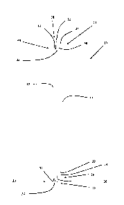
Selon au moins une réalisation, on envisage que la présente invention décrit un panneau mural qui sétend de façon longitudinale entre une première extrémité et une deuxième extrémité et qui comprend une première surface intérieure et une deuxième surface extérieure ainsi quun premier bord longitudinal et un deuxième bord longitudinal. Le premier bord longitudinal comporte une première rainure longitudinale qui entre en contact avec la première surface plane et qui comprend un épaulement perpendiculaire longitudinal joint à une surface plane extérieure longitudinale parallèle à la première surface plane. Le premier bord longitudinal comprend également une deuxième rainure longitudinale qui entre en contact avec la deuxième surface plane et qui comprend un deuxième épaulement perpendiculaire longitudinal joint à une partie inclinée longitudinale. La première rainure longitudinale est plus large que la deuxième rainure longitudinale et le deuxième bord longitudinal comprend une première bride longitudinale qui entre en contact avec la surface et qui comporte un premier bord de bride. Finalement, le premier bord longitudinal comprend une deuxième bride longitudinale en contact avec la deuxième surface plane et comportant un deuxième bord de bride. La première bride étant plus large que la deuxième bride, les deux définissent une rainure longitudinale qui sétend entre elles. Cette dernière comprend un premier mur parallèle à la première surface plane et un deuxième mur disposé du côté opposé et incliné par rapport à la deuxième surface plane.


Abrégé anglais

In at least one embodiment it is contemplated that the present invention provides a wall panel longitudinally extending between a first end and a second end and having a first inner surface, a second outer surface, a first longitudinal edge and a second longitudinal edge, the first longitudinal edge having a first longitudinally extending rabbet that abuts the first planar surface and having a longitudinally extending perpendicular shoulder wall adjoining a longitudinally extending outer planar surface parallel to the first planar surface, a second longitudinally extending rabbit that abuts the second planar surface and having a longitudinally extending perpendicular second shoulder wall adjoining a longitudinally extending sloped portion, the first longitudinally extending rabbet being wider than the second longitudinally extending rabbet, the second longitudinal edge having a longitudinally extending first flange abutting the first planar surface and having a first flange edge, a longitudinally extending second flange abutting the second planar surface and having a second flange edge, the first flange being wider than the second flange, the first flange and the second flange defining a longitudinally extending groove therebetween, the groove having a first wall that is parallel to the first planar surface and an opposing second wall that is angled relative to the second planar surface.

Revendications

Note : Les revendications sont présentées dans la langue officielle dans laquelle elles ont été soumises.


What is claimed is:
1. A wall panel longitudinally extending between a first end and a second end
and having a first
inner surface, a second outer surface, a first longitudinal edge and a second
longitudinal
edge,
the first longitudinal edge having a first longitudinally extending rabbet
that abuts the second
outer surface and having a longitudinally extending perpendicular shoulder
wall adjoining a
longitudinally extending outer planar surface parallel to the second outer
surface, the outer
planar surface having a longitudinally extending inwardly recessed groove
adapted to receive
a mechanical fastener, the longitudinally extending inwardly recessed groove
having a
generally concave cross-sectional profile and oriented parallel to at least
one of the first
longitudinal edge and the second longitudinal edge, and having a second
longitudinally
extending rabbet that abuts the first inner surface and having a
longitudinally extending
perpendicular second shoulder wall adjoining the first longitudinal edge and a
longitudinally
extending sloped portion, the longitudinally extending perpendicular second
shoulder wall
having a first edge that adjoins the longitudinally extending sloped portion
and a second edge
that adjoins the first inner surface, the second edge of the longitudinally
extending
perpendicular second shoulder wall having a rounded profile, the first
longitudinally
extending rabbet being wider than the second longitudinally extending rabbet,
the second longitudinal edge having a longitudinally extending first flange
abutting the first
inner surface and having a first flange edge, a longitudinally extending
second flange
abutting the second outer surface and having a second flange edge, the second
flange being
wider than the first flange, the first flange and the second flange defining a
longitudinally
extending groove therebetween, the groove having a first wall that is parallel
to the first-inner
surface and an opposing second wall that is angled relative to the second
outer surface,
wherein the longitudinally extending inwardly recessed groove is positioned
such that when
an adjacent wall panel is installed, the longitudinally extending inwardly
recessed groove is
covered by the adjacent wall panel.
2. The wall panel of claim 1 wherein at least one of the first longitudinal
edge, the first flange
edge and the second flange edge have a rounded profile.
7
Date Recue/Date Received 2021-06-17

Description

Note : Les descriptions sont présentées dans la langue officielle dans laquelle elles ont été soumises.


= CA 2967459 2017-05-16
Wall Panel with Asymmetrically Rabbeted Edges
Field
The present invention relates to millwork for commercial and residential
applications. More
specifically, the present invention relates to a wall panel for covering
vertical surfaces having
with asymmetrically rabbeted longitudinal edges, such that these longitudinal
edges can engage
with one another when installed on an underlying support surface.
Background
Wall paneling systems have been developed to cover the vertical surfaces of
both interior and
exterior walls. For example, vinyl siding, cedar shakes and cement boards are
all well-known
materials for covering the exterior surfaces of a building while wooden
panelling and gypsum
boards are often used to finish the interior vertical surfaces of a building.
Suitable wall paneling
systems must be attractive yet sufficiently durable for a variety of
applications.
As will be readily appreciated, it is preferable if wall panelling components
are easy to clean and
easy to install on a variety of underlying support surfaces. Moreover, it is
preferable if a wall
panelling system can be securely mounted to a vertical surface without the
appearance of
unsightly mechanical hardware.
Moreover, it is also preferable if a wall panelling system can be manufactured
out of affordable
and durable materials such as fibreboard or plastic composites and also out of
more luxurious
materials such as hardwoods depending on the aesthetic needs of the particular
end user
application.
Accordingly there is a need for a wall paneling system that is easy to clean
and install, durable,
aesthetically appealing and economical to manufacture from a variety of
materials.
Brief Summary
It is contemplated that the present invention can provide a wall panelling
system that is easy to
clean and install, durable, aesthetically appealing and economical to
manufacture from a variety
of materials.
1

CA 2967459 2017-05-16
In at least one embodiment the present invention can provide wall panel
longitudinally extending
between a first end and a second end and having a first inner surface, a
second outer surface, a
first longitudinal edge and a second longitudinal edge, the first longitudinal
edge having a first
longitudinally extending rabbet that abuts the first planar surface and having
a longitudinally
extending perpendicular shoulder wall adjoining a longitudinally extending
outer planar surface
parallel to the first planar surface, a second longitudinally extending rabbit
that abuts the second
planar surface and having a longitudinally extending perpendicular second
shoulder wall
adjoining a longitudinally extending sloped portion, the first longitudinally
extending rabbet
being wider than the second longitudinally extending rabbet, the second
longitudinal edge having
a longitudinally extending first flange abutting the first planar surface and
having a first flange
edge, a longitudinally extending second flange abutting the second planar
surface and having a
second flange edge, the first flange being wider than the second flange, the
first flange and the
second flange defining a longitudinally extending groove therebetween, the
groove having a first
wall that is parallel to the first planar surface and an opposing second wall
that is angled relative
to the second planar surface.
Description of the Drawings
The present invention will be better understood in connection with the
following Figures, in
which:
Figure 1 is a cross-sectional view of a wall panel in accordance with at least
one embodiment of
the present invention;
Figure 2 is a cross-sectional view of the joint between adjacent, installed
wall panels in
accordance with at least one embodiment of the present invention; and
Figures 3A to 3C are perspective views of multiple installed wall panels in a
variety of
configurations in accordance with several specific embodiments of the present
invention.
2

CA 2967459 2017-05-16
Detailed Description of the Embodiments
It is contemplated that the present invention can provide a wall panelling
system that is easy to
clean and install, durable, aesthetically appealing and economical to
manufacture from a variety
of materials.
As will be appreciated by the skilled person, the present wall panel can be
formed out of any
suitable material as required by the specific end user application of the
present invention
including but not limited to fibreboard, plywood, hardwood, softwood, carbon
fibre, various
metals and composite plastics among other suitable materials having the
suitable physical
properties and aesthetic qualities required by the particular end user
application.
Moreover, it is contemplated that the present invention can be formed of by
any suitable
manufacturing process and of any suitable dimensions as required by the needs
of the particular
end user application. For example it is contemplated that the present
invention can be arranged as
a thin, rectangular wall panel or a wide rectangular wall panel depending on
the needs of the
particular end-user application selected.
Moreover, it is contemplated that the present invention can be installed in
vertical arrays or
horizontal arrays on a vertical surface, and moreover in some embodiments can
be installed on a
ceiling or as flooring if suitable materials are selected, as will be readily
appreciated by the
skilled person.
As will be appreciated by the skilled person, it is contemplated that all
adjoining surfaces of the
present invention can be finished with a perfect 90 degree corner or with any
number of radiuses,
chamfers or fillets as will be appreciated by the skilled person.
Turning to Figure 1, at least one embodiment of a cross section of a wall
panel in accordance
with the present invention is illustrated. In this embodiment wall panel 10
has a first inner
surface 12, a second outer surface 14, a first longitudinal edge 16 and a
second longitudinal edge
18. It is contemplated that wall panel 10 extends longitudinally between a
first end and a second
end.
3

CA 2967459 2017-05-16
In this embodiment, first longitudinal edge 16 has a first longitudinally
extending rabbet 20 that
abuts second outer surface 14. In this embodiment first longitudinally
extending rabbet 20 has a
longitudinally extending perpendicular shoulder wall 22 that adjoins both
second outer surface
14 and a longitudinally extending outer planar surface 24 that is parallelly
oriented relative to
first inner surface 12 and second outer surface 14.
In this embodiment, outer planar surface 24 has a longitudinally extending
recessed groove 26
for receiving a mechanical fastener, such as but not limited to a nail, screw,
bolt or rivet. In this
way, it is contemplated that a mechanical fastener can sit within the recessed
groove 26 such that
a second, adjacent wall panel can be mounted flushly against outer planar
surface 24 of a first,
installed wall panel, as will be discussed in further detail below in
connection with Figure 2 and
3A to 3C. Moreover, it is contemplated that recessed groove 26 can be a
continuous groove or a
plurality of separate, discontinuous grooves as required by the needs of the
particular end-user
application selected.
In this embodiment, first longitudinal edge 16 also has a second
longitudinally extending rabbet
30 that abuts the first inner surface 12. In this embodiment second
longitudinally extending
rabbet 30 has a longitudinally extending perpendicular shoulder wall 32 that
adjoins both first
inner surface 12 and a longitudinally extending outer sloped portion 34 that
is angled in
orientation relative to first inner surface 12 and second outer surface 14.
In this embodiment, second longitudinal edge 18 has a longitudinally extending
first flange 40
that abuts first inner surface 12 and has a first flange edge 42 and a
longitudinally extending
second flange 44 that abuts second outer surface 14 and has a second flange
edge 46. In this
embodiment, it is contemplated that second flange 44 is wider than the first
flange 40.
Moreover, in this embodiment it is contemplated that first flange 40 and
second flange 44 defines
a longitudinally extending groove 48 therebetween. In this embodiment it is
contemplated that
groove 48 has a first wall 50 that is parallel to first inner surface 12 and
second outer surface 14
and an opposing second wall 52 that is angled relative to first inner surface
12 and second outer
surface 14.
4

CA 2967459 2017-05-16
In this way and as can be seen in Figure 2, first longitudinal edge 16 of a
first wall panel can fit
within groove 48 defined by first flange 40 and second flange 44 of second
longitudinal edge 18
of an adjacent, second wall panel. As will be appreciated by the skilled
person, mechanical
fasteners can be inserted into recessed groove 26, thereby fixing a first wall
panel in place.
Next and given the geometry of outer sloped portion 34 of a first wall panel
and opposing
second wall 52 of a second wall panel and given that the second flange 44 of
the second wall
panel is wider than the opposing first flange 40 of the second wall panel, the
second wall panel
can be slipped into place such that groove 48 of the second wall panel can
receive first
longitudinal edge 16 of a fixed first wall panel, thereby covering up recessed
groove 26 from
view when the two panels are installed.
In this way a wall panel can be secured to an underlying vertical surface
adjacent first
longitudinal edge 16 by a mechanical fastener positioned within the recessed
groove 26 and
along second longitudinal edge 18 by the locking interaction between the
groove 48 and the first
longitudinal edge 16 of a fixed adjacent panel, as will be readily appreciated
by the skilled
person.
Turning to Figures 3A to 3C, a number of different installation configurations
are illustrated for
a wall panel in accordance with the present invention. With reference to
Figure 3A, several wall
panels 10 can be mounted in a horizontal array on a vertical surface that is
comprised, in this
embodiment, of multiple vertical wall studs 60, although other arrangements
are also
contemplated as will be discussed in further detail below. In this embodiment
it is contemplated
that a mechanical fastener 52 can be inserted into a groove provided in the
outer planar surface
of the wall panel 10, such that wall panel can be mounted directly to studs 60
by way of
mechanical fastener 52.
In this way, wall panel 10 can be secured to the underlying vertical surface
adjacent second
longitudinal edge 18 by a mechanical fastener 52 positioned within the
recessed groove and
along the first longitudinal edge 16 by the locking interaction between the
groove (provided on
second longitudinal edge 18 as discussed above) and first longitudinal edge 16
of a fixed
adjacent wall panel 10, as will be readily appreciated by the skilled person.
5

CA 2967459 2017-05-16
With reference to Figure 3B, several wall panels 10 can be mounted in a
horizontal array on a
vertical surface that is comprised, in this embodiment, of multiple vertical
wall studs 60
supporting an underlying wall surface 62, although other arrangements are also
contemplated as
will be discussed in further detail herein. In this embodiment it is
contemplated that a mechanical
fastener 52 can be inserted into a groove provided in the outer planar surface
of the wall panel
10, such that wall panel can be mounted directly to wall surface 62 by way of
mechanical
fastener 52.
In this way, wall panel 10 can be secured to the underlying vertical surface
adjacent second
longitudinal edge 18 by a mechanical fastener 52 positioned within the
recessed groove and
along the first longitudinal edge 16 by the locking interaction between the
groove (provided on
second longitudinal edge 18 as discussed above) and first longitudinal edge 16
of a fixed
adjacent wall panel 10, as will be readily appreciated by the skilled person.
With reference to Figure 3C, several wall panels 10 can be mounted in a
vertical array on a
vertical surface that is comprised, in this embodiment, of multiple vertical
wall studs 60
supporting an underlying wall surface 62 which in turn has additional
horizontal strapping
members 64, although other arrangements are also contemplated as discussed in
further detail
above. In this embodiment it is contemplated that a mechanical fastener 52 can
be inserted into a
groove provided in the outer planar surface of the wall panel 10, such that
wall panel can be
mounted directly to horizontal strapping members 64 by way of mechanical
fastener 52.
In this way, wall panel 10 can be secured to the underlying vertical surface
adjacent second
longitudinal edge 18 by a mechanical fastener 52 positioned within the
recessed groove and
along the first longitudinal edge 16 by the locking interaction between the
groove (provided on
second longitudinal edge 18 as discussed above) and first longitudinal edge 16
of a fixed
adjacent wall panel 10, as will be readily appreciated by the skilled person.
While the present invention has been described with reference to the
aforementioned
embodiments it will be apparent to anyone skilled in the art that there are
many permutations and
combinations of combining the primary response variables to achieve particular
benefits. All
such permutations and combinations are considered to be within the sphere and
scope of this
invention as defined in the claims appended hereto.
6

Dessin représentatif
Une figure unique qui représente un dessin illustrant l'invention.
États administratifs

2024-08-01 : Dans le cadre de la transition vers les Brevets de nouvelle génération (BNG), la base de données sur les brevets canadiens (BDBC) contient désormais un Historique d'événement plus détaillé, qui reproduit le Journal des événements de notre nouvelle solution interne.

Veuillez noter que les événements débutant par « Inactive : » se réfèrent à des événements qui ne sont plus utilisés dans notre nouvelle solution interne.

Pour une meilleure compréhension de l'état de la demande ou brevet qui figure sur cette page, la rubrique Mise en garde , et les descriptions de Brevet , Historique d'événement , Taxes périodiques et Historique des paiements devraient être consultées.

Historique d'événement

Description Date
Inactive : Octroit téléchargé 2022-02-09
Lettre envoyée 2022-02-08
Accordé par délivrance 2022-02-08
Inactive : Page couverture publiée 2022-02-07
Préoctroi 2021-12-15
Inactive : Taxe finale reçue 2021-12-15
Un avis d'acceptation est envoyé 2021-12-13
Lettre envoyée 2021-12-13
Inactive : Changmnt/correct de nom fait-Corr envoyée 2021-08-06
Inactive : Approuvée aux fins d'acceptation (AFA) 2021-08-04
Inactive : Q2 réussi 2021-08-04
Inactive : Dem retournée à l'exmntr-Corr envoyée 2021-07-30
Retirer de l'acceptation 2021-07-30
Demande de correction du demandeur reçue 2021-07-15
Inactive : Dem reçue: Retrait de l'acceptation 2021-07-15
Inactive : Correspondance - Poursuite 2021-07-15
Un avis d'acceptation est envoyé 2021-07-12
Lettre envoyée 2021-07-12
Un avis d'acceptation est envoyé 2021-07-12
Inactive : Approuvée aux fins d'acceptation (AFA) 2021-07-08
Inactive : Q2 réussi 2021-07-08
Requête pour le changement d'adresse ou de mode de correspondance reçue 2021-06-17
Modification reçue - réponse à une demande de l'examinateur 2021-06-17
Modification reçue - modification volontaire 2021-06-17
Rapport d'examen 2021-03-03
Inactive : Rapport - Aucun CQ 2021-02-23
Lettre envoyée 2021-02-19
Avancement de l'examen jugé conforme - alinéa 84(1)a) des Règles sur les brevets 2021-02-19
Lettre envoyée 2021-02-19
Requête d'examen reçue 2021-02-09
Exigences pour une requête d'examen - jugée conforme 2021-02-09
Modification reçue - modification volontaire 2021-02-09
Inactive : Taxe de devanc. d'examen (OS) traitée 2021-02-09
Toutes les exigences pour l'examen - jugée conforme 2021-02-09
Inactive : Avancement d'examen (OS) 2021-02-09
Modification reçue - modification volontaire 2021-02-09
Représentant commun nommé 2020-11-07
Inactive : COVID 19 - Délai prolongé 2020-05-14
Représentant commun nommé 2019-10-30
Lettre envoyée 2019-02-14
Requête visant le maintien en état reçue 2019-01-30
Demande publiée (accessible au public) 2018-11-16
Inactive : Page couverture publiée 2018-11-15
Inactive : Transferts multiples 2018-10-05
Exigences relatives à la révocation de la nomination d'un agent - jugée conforme 2018-07-30
Inactive : Lettre officielle 2018-07-30
Exigences relatives à la nomination d'un agent - jugée conforme 2018-07-30
Demande visant la révocation de la nomination d'un agent 2018-07-19
Demande visant la nomination d'un agent 2018-07-19
Inactive : CIB attribuée 2017-06-21
Inactive : CIB en 1re position 2017-06-21
Inactive : CIB attribuée 2017-06-21
Inactive : Certificat dépôt - Aucune RE (bilingue) 2017-05-30
Demande reçue - nationale ordinaire 2017-05-24

Historique d'abandonnement

Il n'y a pas d'historique d'abandonnement

Taxes périodiques

Le dernier paiement a été reçu le 2022-01-18

Avis : Si le paiement en totalité n'a pas été reçu au plus tard à la date indiquée, une taxe supplémentaire peut être imposée, soit une des taxes suivantes :

  • taxe de rétablissement ;
  • taxe pour paiement en souffrance ; ou
  • taxe additionnelle pour le renversement d'une péremption réputée.

Les taxes sur les brevets sont ajustées au 1er janvier de chaque année. Les montants ci-dessus sont les montants actuels s'ils sont reçus au plus tard le 31 décembre de l'année en cours.
Veuillez vous référer à la page web des taxes sur les brevets de l'OPIC pour voir tous les montants actuels des taxes.

Historique des taxes

Type de taxes Anniversaire Échéance Date payée
Taxe pour le dépôt - générale 2017-05-16
Enregistrement d'un document 2018-10-05
TM (demande, 2e anniv.) - générale 02 2019-05-16 2019-01-30
TM (demande, 3e anniv.) - générale 03 2020-05-19 2020-05-15
Requête d'examen - générale 2022-05-16 2021-02-09
Avancement de l'examen 2021-02-09 2021-02-09
TM (demande, 4e anniv.) - générale 04 2021-05-17 2021-04-15
2021-07-15 2021-07-15
Taxe finale - générale 2022-04-13 2021-12-15
TM (demande, 5e anniv.) - générale 05 2022-05-16 2022-01-18
TM (brevet, 6e anniv.) - générale 2023-05-16 2023-01-16
TM (brevet, 7e anniv.) - générale 2024-05-16 2024-01-16
Titulaires au dossier

Les titulaires actuels et antérieures au dossier sont affichés en ordre alphabétique.

Titulaires actuels au dossier
MOULURE ALEXANDRIA MOULDING INC.
Titulaires antérieures au dossier
FUZHONG LIU
JERRY CHABOT
LUC TITLEY
MARC CAMPEAU
MARC HURTUBISE
SEAN CADNEY
Les propriétaires antérieurs qui ne figurent pas dans la liste des « Propriétaires au dossier » apparaîtront dans d'autres documents au dossier.
Documents

Pour visionner les fichiers sélectionnés, entrer le code reCAPTCHA :


Pour visualiser une image, cliquer sur un lien dans la colonne description du document. Pour télécharger l'image (les images), cliquer l'une ou plusieurs cases à cocher dans la première colonne et ensuite cliquer sur le bouton "Télécharger sélection en format PDF (archive Zip)" ou le bouton "Télécharger sélection (en un fichier PDF fusionné)".

Liste des documents de brevet publiés et non publiés sur la BDBC .

Si vous avez des difficultés à accéder au contenu, veuillez communiquer avec le Centre de services à la clientèle au 1-866-997-1936, ou envoyer un courriel au Centre de service à la clientèle de l'OPIC.


Description du
Document 
Date
(aaaa-mm-jj) 
Nombre de pages   Taille de l'image (Ko) 
Description 2017-05-15 6 303
Abrégé 2017-05-15 1 33
Revendications 2017-05-15 1 40
Dessins 2017-05-15 5 121
Dessin représentatif 2018-10-09 1 3
Revendications 2021-02-08 1 50
Revendications 2021-06-16 1 70
Dessin représentatif 2022-01-05 1 4
Paiement de taxe périodique 2024-01-15 1 25
Certificat de dépôt 2017-05-29 1 202
Rappel de taxe de maintien due 2019-01-16 1 112
Courtoisie - Réception de la requête d'examen 2021-02-18 1 435
Avis du commissaire - Demande jugée acceptable 2021-07-11 1 576
Courtoisie - Avis d'acceptation considéré non envoyé 2021-07-29 1 404
Avis du commissaire - Demande jugée acceptable 2021-12-12 1 579
Paiement de taxe périodique 2019-01-29 1 58
Paiement de taxe périodique 2020-05-14 1 25
Avancement d'examen (OS) / Requête d'examen / Modification / réponse à un rapport 2021-02-08 3 121
Courtoisie - Requête pour avancer l’examen - Conforme (OS) 2021-02-18 1 180
Demande de l'examinateur 2021-03-02 4 217
Paiement de taxe périodique 2021-04-14 1 25
Modification / réponse à un rapport 2021-06-16 13 2 876
Changement à la méthode de correspondance 2021-06-16 3 59
Correspondance de la poursuite 2021-07-14 5 152
Retrait d'acceptation 2021-07-14 5 165
Courtoisie - Accusé de correction d’une erreur dans le nom 2021-08-05 1 192
Modification au demandeur/inventeur 2021-07-14 5 151
Taxe finale 2021-12-14 3 81
Paiement de taxe périodique 2022-01-17 1 25
Certificat électronique d'octroi 2022-02-07 1 2 527
Paiement de taxe périodique 2023-01-15 1 25