Note : Les descriptions sont présentées dans la langue officielle dans laquelle elles ont été soumises.
CA 02971505 2017-06-19
CA Application
Nat'l Entry of PCT Application No. PCT/CN2016/075611
Blakes Ref. 13342/00021
FLOOR BRUSH ASSEMBLY FOR UPRIGHT VACUUM CLEANER AND UPRIGHT
VACUUM CLEANER WITH THE SAME
FIELD
The present disclosure relates to a field of cleaning machines, and more
particularly to a floor
brush assembly for an upright vacuum cleaner and an upright vacuum cleaner
with the same.
BACKGROUND
A vacuum cleaner in the related art includes two motors to drive a brushroll
and a fan
respectively, and the motor for driving the fan is usually disposed
horizontally. That is, a motor
shaft of the motor is parallel to a mounting platform of the motor, such that
a motor housing may
have a huge volume and the motor may occupy a large area. Moreover, the motor
disposed
horizontally limits the arrangement of other parts of the vacuum cleaner to a
great extent.
SUMMARY
The present disclosure aims to solve at least one of the technical problems
existing in the
related art. Thus, embodiments of the present disclosure provide an upright
vacuum cleaner, and a
floor brush assembly of the upright vacuum cleaner has a simple and compact
structure that
occupies small space and is easy to assemble or disassemble, which may
facilitate diverse
arrangements of various parts.
Embodiments of the present disclosure further provide an upright vacuum
cleaner with the
above floor brush assembly. The upright vacuum cleaner has a simple and
compact structure that
occupies small space and is easy to operate in a stable and reliable manner.
According to embodiments of a first aspect of the present disclosure, the
floor brush assembly
for the upright vacuum cleaner includes a brushroll; a motor driving the
brushroll to roll via a
drive belt that is winded upon a motor shaft of the motor and a central part
of the brushroll; and a
brushroll casing provided outside the brushroll, having a dust suction port
and defining a brushroll
air-suction channel and a drive-belt mounting chamber for mounting the drive
belt, in which the
brushroll air-suction channel includes a first air-suction channel and a
second air-suction channel
located at both sides of the drive-belt mounting chamber.
In the floor brush assembly for the upright vacuum cleaner according to
embodiments of the
23153755.1 1
CA 02971505 2017-06-19
CA Application
Nat'l Entry of PCT Application No. PCT/CN2016/075611
Blakes Ref. 13342/00021
present disclosure, it is possible to achieve the effect of dust suction at
both sides of the drive belt
by disposing the first air-suction channel and the second air-suction channel
at both sides of the
drive belt, so as to expand the range of dust suction and improve the working
efficiency of the
upright vacuum cleaner. Moreover, the upright vacuum cleaner controls the
rotation of the
brushroll and generation of a dust suction flow simultaneously by one motor,
which occupies
smaller space with fewer parts and realizes synchronous control over dust
sweep and dust suction.
Additionally, the motor of the upright vacuum cleaner is disposed vertically
to reduce the
occupation space of the upright vacuum cleaner and facilitate diverse
arrangements of various
parts of the upright vacuum cleaner.
According to an example of the present disclosure, a rotating axis of the
motor is provided in
perpendicular to a rotating axis of the brushroll, and the drive belt is
provided at a twist angle of
90 .
According to an example of the present disclosure, the rotating axis of the
motor is disposed
vertically; the floor brush assembly further includes a stopping piece
provided below the drive belt
and adjacent to the motor to prevent the drive belt from slipping off from the
motor shaft.
According to an example of the present disclosure, the first air-suction
channel and the second
air-suction channel are arranged symmetrically with respect to the drive belt.
According to an example of the present disclosure, the brushroll includes a
first brushroll
section provided with bristles, a second brushroll section provided with
bristles, and a
connecting-shaft section connected between the first brushroll section and the
second brushroll
section, in which the drive belt is winded upon the motor shaft and the
connecting-shaft section to
make the motor to drive the brushroll to roll.
According to an example of the present disclosure, the brushroll further
includes: a first baffle
provided between the connecting-shaft section and the first brushroll section
to separate the
connecting-shaft section and the first brushroll section; and a second baffle
provided between the
connecting-shaft section and the second brushroll section to separate the
connecting-shaft section
and the second brushroll section.
According to an example of the present disclosure, the first brushroll section
includes a first
body and a first bristle provided on the first body; the second brushroll
section includes a second
body and a second bristle provided on the second body; there is a plurality of
first bristles and each
first bristle is spirally winded about the first body in a first direction;
there is a plurality of second
23153755.1 2
CA 02971505 2017-06-19
CA Application
Nat'l Entry of PCT Application No. PCT/CN2016/075611
Blakes Ref. 13342/00021
bristles and each second bristle is spirally winded about the second body in a
second direction, the
first direction being opposite to the second direction.
According to an example of the present disclosure, the first brushroll section
and the second
brushroll section are provided symmetrically relative to the drive belt; the
respective central axes
of the first brushroll section, the second brushroll section and the
connecting-shaft section are
located in the same line.
According to an example of the present disclosure, the brushroll casing
includes a lower
casing and an upper casing connected to a top of the lower casing; the first
air-suction channel and
the second air-suction channel are defined by the upper casing and/or the
lower casing.
According to an example of the present disclosure, the floor brush assembly
further includes a
tensioning wheel provided opposite to a part of the drive belt adjacent to the
brushroll to tension
the drive belt.
According to embodiments of a second aspect of the present disclosure, the
upright vacuum
cleaner includes: the floor brush assembly for the upright vacuum cleaner
according to the above
embodiments that further includes a motor housing provided outside the motor,
having an air
exhaust hole, a dirty air outlet and a clean air inlet, and defining a motor
air-suction channel and a
motor air-exhaust channel, in which the motor air-suction channel is
communicated between the
brushroll air-suction channel and the dirty air outlet while the motor air-
exhaust channel is
communicated between the clean air inlet and the air exhaust hole; and a body
assembly including
a body, and a dirt cup mounted on the body and having a separating chamber
communicated with
the dirty air outlet and the clean air inlet respectively.
According to an example of the present disclosure, the dirty air outlet is
connected to the dirt
cup by an air-inlet pipe assembly so as to be communicated with the separating
chamber; the
air-inlet pipe assembly includes: an air-inlet pipe provided on the motor
housing and having a first
end connected to the dirty air outlet, and a first hose connected between a
second end of the
air-inlet pipe and an air inlet of the dirt cup.
According to an example of the present disclosure, the first hose is
detachably connected
between the second end of the air-inlet pipe and the air inlet of the dirt
cup.
According to an example of the present disclosure, the body defines a body air-
exhaust
channel that has a first end connected to an air outlet of the dirt cup and
communicated with the
separating chamber, and a second end communicated with the clean air inlet.
23153755.1 3
CA 02971505 2017-06-19
CA Application
Nat'l Entry of PCT Application No. PCT/CN2016/075611
Blakes Ref. 13342/00021
According to an example of the present disclosure, the second end of the body
air-exhaust
channel is communicated with the clean air inlet by an air exhaust pipe.
According to an example of the present disclosure, the motor air-suction
channel includes a
first branch channel communicated to the first air-suction channel and a
second branch channel
communicated to the second air-suction channel; the first branch channel and
the second branch
channel are converged and communicated with the dirty air outlet.
According to an example of the present disclosure, the first branch channel
and the second
branch channel are defined by the motor casing of the motor and the motor
housing together, and
constitute a stereoscopic space with a substantially annular cross section.
According to an example of the present disclosure, the dirty air outlet and
the clean air inlet
are arranged axially symmetrically with respect to a central line of the motor
housing.
According to an example of the present disclosure, the upright vacuum cleaner
further
includes a directional control valve having a first air hole, a second air
hole and a third air hole, in
which the first air hole is communicated with the brushroll air-suction
channel, the second air hole
with the air inlet of the dirt cup, the third air hole with the outside, and
the directional control
valve is configured to switch between a first state where the first air hole
and the second air hole
are communicated and a second state where the second air hole and the third
air hole are
communicated.
According to an example of the present disclosure, the directional control
valve includes: a
three-way pipe including a first pipe section, a second pipe section and a
third pipe section
communicated with one another, the first air hole defined by a free end of the
first pipe section and
the second air hole defined by a free end of the second pipe section; and a
two-way pipe including
a fourth pipe section and a fifth pipe section communicated with each other,
the third air hole
defined by a free end of the fourth pipe section and a fourth air hole defined
by the fifth pipe
section, in which at least a part of the fifth pipe section is inserted into
the third pipe section and is
movable between a first position where the first air hole is communicated with
the second air hole
and a second position where the fourth air hole is communicated with the
second air hole; a first
end of the fifth pipe section is connected with the fourth pipe section and a
second end of the fifth
pipe section has a closed end wall, and the fourth air hole is formed in a
side wall of the second
end of the fifth pipe section; an end of the fourth pipe section connected
with the fifth pipe section
abuts against a free end of the third pipe section when the two-way pipe moves
to the second
23153755.1 4
CA 02971505 2017-06-19
CA Application
Nat'l Entry of PCT Application No. PCT/CN2016/075611
Blakes Ref. 13342/00021
position.
According to an example of the present disclosure, the upright vacuum cleaner
further
includes a second hose having a first end communicated with the outside and a
second end
connected with the third air hole.
According to an example of the present disclosure, the dirt cup includes the
air inlet and the
air outlet; and the body assembly further includes: a filter provided in the
dirt cup and having a
filter inlet and a filter outlet communicated between the filter inlet and the
air outlet; and a
cyclonic cone assembly having a cyclone and a cyclonic guide, in which a first
end of the cyclone
is communicated with the air inlet, and the cyclonic guide is fitted in a
second end of the cyclone
and is detachably fitted over the filter to spirally guide dirty air
introduced into the cyclone from
the air inlet to the filter inlet.
According to an example of the present disclosure, the cyclonic guide includes
a first
cylindrical surface and the filter includes a second cylindrical surface, the
cyclonic guide being
detachably fitted over the filter by the first cylindrical surface and the
second cylindrical surface.
According to an example of the present disclosure, the filter is configured as
a cylinder with
an open end and a closed end; the open end of the filter defines the filter
outlet and the filter inlet
is formed in a side wall of the filter.
According to an example of the present disclosure, the filter includes a first
section and a
second section; the first section is configured to be a solid cylinder while
the second section is
configured to be a hollow cylinder; a first end of the second section is
connected with a first end of
the first section and a second end of the second section is open to define the
filter outlet, and the
filter inlet is formed in a side wall of the second section.
According to an example of the present disclosure, the filter inlet includes a
plurality of filter
pores that are evenly spaced apart and distributed in an axial direction
and/or a circumferential
direction of the second section.
According to an example of the present disclosure, the cyclonic guide
includes: a sleeve
having a portion fitted over the first section; and a guide plate provided
between the sleeve and the
cyclone to define, along with the sleeve and the cyclone, a spiral channel for
the dirty air to
spirally flow from the air inlet to the filter inlet.
According to an example of the present disclosure, the sleeve and the guide
plate are molded
integrally.
23153755.1 5
CA 02971505 2017-06-19
CA Application
Nat'l Entry of PCT Application No PCT/CN2016/075611
Blakes Ref. 13342/00021
According to an example of the present disclosure, the cyclone and the
cyclonic guide are
connected with thread or in a hot-melt manner via ultrasonic waves.
Additional aspects and advantages of embodiments of present disclosure will be
given in part
in the following descriptions, become apparent in part from the following
descriptions, or be
learned from the practice of the present disclosure.
BRIEF DESCRIPTION OF THE DRAWINGS
Fig. 1 is a schematic view of an upright vacuum cleaner according to an
embodiment of the
present disclosure;
Fig. 2 is a side view of the upright vacuum cleaner of Fig. 1 when a motor is
located at a first
oblique position;
Fig. 3 is a side view of the upright vacuum cleaner of Fig. 1 when a motor is
located at a first
upright position;
Fig. 4 is a schematic view of the upright vacuum cleaner of Fig. 1 in a
direction;
Fig. 5 is a schematic view of an upright vacuum cleaner according to another
embodiment of
the present disclosure;
Fig. 6 is a side view of the upright vacuum cleaner of Fig. 5;
Fig. 7 is a schematic view of a floor brush assembly for an upright vacuum
cleaner according
to an embodiment of the present disclosure;
Fig. 8 is a schematic view of a floor brush assembly for an upright vacuum
cleaner according
to another embodiment of the present disclosure;
Fig. 9 is a top view of the structure shown in Fig. 8;
Fig. 10 is a side view of the structure shown in Fig. 7;
Fig. 11 is a bottom view of the structure shown in Fig. 7;
Fig. 12 is a schematic view of an internal channel of the structure shown in
Fig. 11;
Fig. 13 is a rear view of an internal channel of the structure shown in Fig.
8;
Fig. 14 is a schematic view of a brushroll of an upright vacuum cleaner
according to an
embodiment of the present disclosure;
Fig. 15 is a front view of the brushroll of the upright vacuum cleaner shown
in Fig. 14;
Fig. 16 is a schematic view of a directional control valve of an upright
vacuum cleaner at a
working state according to an embodiment of the present disclosure;
23153755.1 6
CA 02971505 2017-06-19
CA Application
Nat'l Entry of PCT Application No. PCT/CN2016/075611
Blakes Ref. 13342/00021
Fig. 17 is a schematic view of a directional control valve of an upright
vacuum cleaner at
another working state according to an embodiment of the present disclosure;
Fig. 18 is a schematic view of a floor brush assembly for an upright vacuum
cleaner
according to an embodiment of the present disclosure;
Fig. 19 is an enlarged view of part A of Fig. 18;
Fig. 20 is a schematic view of a bridging member of an upright vacuum cleaner
according to
an embodiment of the present disclosure;
Fig. 21 is a schematic view of a cyclonic separating device according to an
embodiment of
the present disclosure;
Fig. 22 is an explosive view of a partial structure of a cyclonic separating
device according to
an embodiment of the present disclosure;
Fig. 23 is a perspective view of a cyclonic cone assembly of a cyclonic
separating device
according to an embodiment of the present disclosure.
Reference numerals:
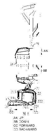
1 upright vacuum cleaner
100 brushroll assembly
11 brushroll
111 first brushroll section
1111 first body
1112 first bristle
112 second brushroll section
1121 second body
1122 second bristle
113 connecting-shaft section
114 first baffle
115 second baffle
12 brushroll casing
122 brushroll air-suction channel
1221 first air-suction channel
1222 second air-suction channel
23153755.1 7
CA 02971505 2017-06-19
CA Application
Nat'l Entry of PCT Application No. PCT/CN2016/075611
Blakes Ref. 13342/00021
123 drive-belt mounting chamber
124 upper casing
125 lower casing
13 drive belt
14 tensioning wheel
200 motor assembly
21 motor housing
211 dirty air outlet
212 clean air inlet
213 air exhaust hole
214 dirty air output pipe
215 clean air input pipe
216 motor air-suction channel
2161 first branch channel
2162 second branch channel
22 motor
221 motor shaft
222 motor casing
300 body assembly
31 body
311 body air-exhaust channel
32 bridging member
321 top plate
3211 first clearance groove
3212 second clearance groove
322 side plate
33 connecting pipe assembly
331 first connecting pipe
332 second connecting pipe
34 positioning assembly
341 first positioning piece
23153755.1 8
CA 02971505 2017-06-19
CA Application
Nat'l Entry of PCT Application No. PCT/CN2016/075611
Blakes Ref. 13342/00021
342 second positioning piece
35 limiting column
36 elastic member
37 dirt cup
370 dirt-cup body
3701 dirt-cup upper cover
3702 dirt-cup lower cover
371 separating chamber
372 air inlet
373 air outlet
38 wheel
39 air exhaust pipe
51 air-inlet pipe
52 first hose
600 directional control valve
61 three-way pipe
611 first pipe section
612 second pipe section
613 third pipe section
62 two-way pipe
621 fourth pipe section
622 fifth pipe section
631 first air hole
632 second air hole
633 third air hole
634 fourth air hole
900 cyclonic separating device
92 filter
92a filter inlet
922a filter pore
92b filter outlet
23153755.1 9
CA 02971505 2017-06-19
CA Application
Nat'l Entry of PCT Application No. PCT/CN2016/075611
Blakes Ref. 13342/00021
920 second cylindrical surface
921 first section
922 second section
93 cyclonic cone assembly
930 first cylindrical surface
930a spiral channel
931 cyclone
932 cyclonic guide
9321 sleeve
9322 guide plate
94 filter cotton assembly
DETAILED DESCRIPTION
Embodiments of the present disclosure will be described in detail and examples
of the
embodiments will be illustrated in the drawings, where same or similar
reference numerals are
used to indicate same or similar members or members with same or similar
functions. The
embodiments described herein with reference to drawings are explanatory, which
are used to
illustrate the present disclosure, but shall not be construed to limit the
present disclosure.
The following description provides many different embodiments or examples to
realize
different structures of the present disclosure. To simplify the description of
the present disclosure,
components and configurations in specific examples are elaborated. Of course,
they are only
explanatory, and are not intended to limit the present disclosure. Moreover,
reference numbers
and/or letters may be repeated in different examples of the present disclosure
for the purpose of
simplicity and clarity, which shall not be constructed to indicate the
relationships among various
embodiments and/or configurations. In addition, the present disclosure
provides examples of
various specific processes and materials, but applicability of other processes
and/or utilization of
other materials are conceivable for those skilled in the art.
A floor brush assembly for an upright vacuum cleaner 1 according to
embodiments of the first
aspect of the present disclosure will be described with reference to Figs. 1
to 20.
The floor brush assembly of the upright vacuum cleaner 1 according to the
embodiments of
the present disclosure includes a brushroll 11, a motor 22 and a brushroll
casing 12. Specifically,
23153755.1 10
CA 02971505 2017-06-19
CA Application
Nat'l Entry of PCT Application No. PCT/CN2016/075611
Blakes Ref. 13342/00021
the motor 22 drives the brushroll 11 to roll via a drive belt 13 that is
winded upon a motor shaft
221 of the motor 22 and a central part of the brushroll 11; the brushroll
casing 12 is provided
outside the brushroll 11, has a dust suction port and defines a brushroll air-
suction channel 122
communicated with the dust suction port and a drive-belt mounting chamber 123
for mounting the
drive belt 13, in which the brushroll air-suction channel 122 includes a first
air-suction channel
1221 and a second air-suction channel 1222 located at both sides of the drive-
belt mounting
chamber 123.
Referring to Fig. 1 and Fig. 2, the brushroll 11 extends along a horizontal
direction (i.e. a
left-and-right direction as shown in Fig. 1); a motor 22 is disposed in rear
of the brushroll 11, and
the motor shaft 221 of the motor 22 is connected with the brushroll 11 to
drive the rotation of the
brushroll 11 around its own center of rotation, so as to sweep the floor;
dusts, debris and dirty air
swept by the brushroll 11 are sucked into a brushroll air-suction channel 122
via a dust suction
port of the brushroll casing 12 and are processed in the body assembly 300.
Further, the brushroll casing 12 has the brushroll air-suction channel 122 and
the drive-belt
mounting chamber 123 for mounting the drive belt 13. Referring to Fig. 9, the
brushroll casing 12
is formed as a T shape. That is, the brushroll casing 12 includes a brush
casing extending along the
horizontal direction (i.e. the left-and-right direction shown in Fig. 11) and
a belt casing extending
along the vertical direction (i.e. the front-and-rear direction shown in Fig.
11). The brushroll
casing 12 defines the drive-belt mounting chamber 123 and the brushroll air-
suction channel 122
located at both sides of the drive-belt mounting chamber 123; the brushroll 11
is rotatably
provided in the brushroll air-suction channel 122 and the rotating axis of the
brushroll 11 extends
along a length direction of the brush casing; the drive belt 13 is rotatably
provided within the
drive-belt mounting chamber 123. Further, the brushroll air-suction channel
122 and the drive belt
13 are separated. The second end of the drive belt 13 is winded upon the
brushroll 11 and the first
end thereof is winded upon the motor shaft 221; the drive-belt mounting
chamber 123 and the
brushroll air-suction channel 122 are separated to prevent the dust and debris
in the brushroll
air-suction channel 122 from winding upon the drive belt 13 and the motor
shaft 221 and to
guarantee the stability and reliability of the operation of the drive belt 13
and the motor 22, so as
to ensure the normal working of the upright vacuum cleaner 1.
The first air-suction channel 1221 and the second air-suction channel 1222 are
located at both
sides of the drive-belt mounting chamber 123 respectively and spaced apart
from the drive-belt
23153755.1 11
CA 02971505 2017-06-19
CA Application
Nat'l Entry of PCT Application No. PCT/CN2016/075611
Blakes Ref. 13342/00021
mounting chamber 123. That is, the brushroll air-suction channel 122 is
separated from the drive
belt 13. The first end of the drive belt 13 is winded upon the lower end of
the motor shaft 221 and
the second end of the drive belt 13 is winded upon the brushroll 11; the first
air-suction channel
1221 and the second air-suction channel 1222 are spaced apart and disposed at
the left and right
sides of the drive belt 13, such that the dirty air and dust sucked through
the dust suction port of
the brushroll casing 12 are delivered into the first air-suction channel 1221
and the second
air-suction channel 1222 respectively, and then mixed together to flow into
the dirt cup 37. The
drive-belt mounting chamber 123 and the brushroll air-suction channel 122 are
separated to
prevent the dust and debris in the brushroll air-suction channel 122 from
winding upon the drive
belt 13 and the motor shaft 221 and to guarantee the stability and reliability
of the operation of the
drive belt 13 and the motor 22, so as to ensure the normal working of the
upright vacuum cleaner
1.
In the floor brush assembly of the upright vacuum cleaner 1 according to
embodiments of the
present disclosure, it is possible to achieve the effect of dust suction at
both sides of the drive belt
13 by disposing the first air-suction channel 1221 and the second air-suction
channel 1222 at both
sides of the drive belt 13, so as to expand the range of dust suction and
improve the working
efficiency of the upright vacuum cleaner 1. Moreover, the upright vacuum
cleaner 1 controls the
rotation of the brushroll 11 and generation of a dust suction flow
simultaneously by one motor,
which occupies smaller space with fewer parts but realizes synchronous control
over dust sweep
and dust suction. Additionally, the motor of the upright vacuum cleaner 1 is
disposed vertically to
reduce the occupation space of the upright vacuum cleaner and facilitate
diverse arrangements of
various parts of the upright vacuum cleaner 1.
Preferably, according to an embodiment of the present disclosure, the first
air-suction channel
1221 and the second air-suction channel 1222 are disposed symmetrically with
respect to the drive
belt 13. That is, the first air-suction channel 1221 has the same length and
the same sectional area
as the second air-suction channel 1222. That is, the air suction capacities of
the first air-suction
channel 1221 and the second air-suction channel 1222 are equal, such that the
dirty air and dust
sucked via the air suction inlet enter the dirt cup 37 evenly through the
first air-suction channel
1221 and the second air-suction channel 1222 to guarantee the balance of dust
suction at both sides
of the drive belt 13.
Alternatively, the rotating axis of the motor 22 is disposed in perpendicular
to that of the
23153755.1 12
CA 02971505 2017-06-19
CA Application
Nat'l Entry of PCT Application No. PCT/CN2016/075611
Blakes Ref. 13342/00021
brushroll 11, and the drive belt 13 is disposed at the twist angle of 900.
Referring to Fig. 1 and Fig.
2, the brushroll 11 is disposed in a horizontal plane and the rotating axis of
the brushroll 11
extends along the horizontal direction; the motor 22 is disposed vertically
within a motor housing
21 and the motor shaft 221 of the motor 22 is located in a vertical plane
perpendicular to the
rotating axis of the brushroll 11. That is, the rotating axis of the motor
shaft 221 of the motor 22
and the rotating axis of the brushroll 11 are disposed in perpendicular to
each other, so the upper
half of the drive belt 13 and the lower half thereof are both twisted between
the brushroll 11 and
the motor shaft 221 for one time, and the twist angle of two ends of each
section of the drive belt
13 is 90 .
In some specific examples of the present disclosure, the motor shaft 221 of
the motor 22 is
disposed vertically. Specifically, the motor 22 mainly includes a motor body
and a motor casing
222. The motor body is provided within the motor casing 222 and is constituted
by a core and the
motor shaft 221. The motor shaft 221 of the motor 22 is connected with the
core of the motor 22,
and the motor 22 is arranged vertically. When the upright vacuum cleaner 1 is
in non-working
state, an upper end of the motor shaft 221 is disposed obliquely backwards
relative to the vertical
direction (i.e. the up-and-down direction shown in Fig. 3). During the dust
suction of the upright
vacuum cleaner 1, a central axis of the motor shaft 221 extends along the
vertical direction. That
is, the first end of the motor shaft 221 of the upright vacuum cleaner 1 may
extend downwards
relative to the core along the vertical direction (i.e. the up-and-down
direction shown in Fig. 3).
The first end of the drive belt 13 is winded upon the lower end of the motor
shaft 221 and the
second end of the drive belt 13 is winded upon the brushroll 11. Because the
rotating axis of the
brushroll 11 is disposed in the horizontal plane, the drive belt 13 is twisted
at least one time
between the brushroll 11 and the motor shaft 221. That is, the twist angle of
the drive belt 13
between the alterable contact point of the drive belt 13 and the motor shaft
221 and the alterable
contact point of the drive belt 13 and the brushroll 11 is 90 .
When the body 31 is at the upright position, the axis of the motor shaft 221
of the motor 22 is
disposed obliquely backwards relative to the axis of the motor housing 21, in
which case the two
ends of the drive belt 13 are winded upon the motor shaft 221and the brushroll
11 respectively, but
the drive belt 13 is loosened. When the body 31 is at the oblique position,
the axis of the motor 22
extends along the vertical direction. That is, the motor 22 is in an upright
state, such that the drive
belt 13 is tensioned. Specifically, when the body 31 is manipulated from the
upright position to the
23153755.1 13
CA 02971505 2017-06-19
CA Application
Nat'l Entry of PCT Application No. PCT/CN2016/075611
Blakes Ref. 13342/00021
oblique position, the lower end of the motor shaft 221 moves backwards
gradually, to increase the
distance between the lower end of the motor shaft 221 and the brushroll 11 and
thus to tension the
drive belt 13.
The floor brush assembly of the upright vacuum cleaner 1 further includes a
stopping piece
(not shown) disposed below the drive belt 13 and adjacent to the motor 22 to
prevent the drive belt
13 from falling off from the motor shaft 221. For example, the stopping piece
may be a snap
spring provided on the motor shaft 221, and the snap spring may be provided at
a free end of the
motor shaft 221 to locate an end of the drive belt 13 connected with the motor
shaft 221 above the
snap spring, so as to avoid the drive belt 13 from sliding off from the motor
shaft 221. The
stopping piece may be constituted by the structure of the free end of the
motor shaft 221. Of
course, the present disclosure is not limited thereby ¨ the stopping piece may
be provided on
another part below the drive belt 13 to prevent the drive belt 13 from sliding
off from the motor
shaft 221. Thus, by disposing the stopping piece below the drive belt 13, it
is possible to prevent
the drive belt 13 from sliding off from the motor shaft 221 and guarantee the
reliability of the
operation of the drive belt 13, further to ensure normal operation of the
upright vacuum cleaner 1.
The brushroll 11 mainly includes a first brushroll section 111, a second
brushroll section 112
and a connecting-shaft section 113. Specifically, an end of the first
brushroll section 111 and an
end of the second brushroll section 112 are connected with two ends of the
connecting-shaft
section 113 respectively. Referring to Fig. 1 and Fig. 2, the brushroll 11 is
rotatably provided in the
brushroll casing 12, and the motor 22 and the brushroll 11 are connected to
drive the rotation of
the brushroll 11 around its rotating axis. The first brushroll section 111,
the second brushroll
section 112 and the connecting-shaft section 113 are configured as columns
extending along the
horizontal direction (i.e. the left-and-right direction shown in Fig. 14). The
right end of the first
brushroll section 111 is connected with the left end of the connecting-shaft
section 113; the left
end of the second brushroll section 112 is connected with the right end of the
connecting-shaft
section 113. Bristles may be provided to the respective outer side walls of
the first brushroll
section 111 and the second brushroll section 112 to clean the corresponding
walls, but no bristle is
provided on the connecting-shaft section 113 to facilitate connection with the
drive belt 13.
Further, the drive belt 13 is winded upon the motor shaft 221 of the motor 22
and the
connecting-shaft section 113, such that the brushroll 11 is driven to roll by
the motor 22. Referring
Fig. 2, the motor 22 is provided in the motor housing 21 and is connected with
a fan and the
23153755.1 14
CA 02971505 2017-06-19
CA Application
Nat'l Entry of PCT Application No. PCT/CN2016/075611
Blakes Ref. 13342/00021
brushroll 11 respectively. The motor 22 may drive the rotation of the fan to
generate an air flow to
provide a vacuuming power; and the motor 22 may drive the rotation of the
brushroll 11 around its
own axis to realize the purpose of cleaning the floor.
Referring to Fig. 2, the brushroll 11 and the motor 22 are spaced apart in the
front-and-rear
direction, and the brushroll 11 is located at the front side of the motor 22.
The first end of the drive
belt 13 is winded upon the motor shaft 221 of the motor 22 while the second
end of the drive belt
13 is winded upon the brushroll 11. When the motor shaft 221 of the motor 22
rotates, the motor
shaft 221 drives the rotation of the drive belt 13 due to the frictional
resistance between the motor
shaft 221 and the surface of the drive belt 13. Similarly, the drive belt 13
drives the rotation of the
brushroll 11 around its own axis due to the frictional resistance between the
brushroll 11 and the
surface of the drive belt 13, so as to realize the rotation of the brushroll
11 driven by the motor 22.
By disposing the drive belt 13 between the motor 22 and the brushroll 11, the
motor 22 may
drive the fan and the rotation of the brushroll 11 simultaneously. Compared
with the vacuum
cleaner in the related art that realizes control over the rotation of the fan
and the brushroll 11
respectively by two motors 22, the upright vacuum cleaner 1 has the simple
structure and fewer
parts, so it occupies the small space and is easy to assemble, which improves
the assembling
efficiency, and may realize synchronous control over dust sweep and dust
suction as well.
Additionally, the motor of the upright vacuum cleaner 1 is disposed vertically
to reduce the
occupation space of the upright vacuum cleaner and facilitate diverse
arrangements of various
parts of the upright vacuum cleaner 1.
The brushroll 11 further includes a first baffle 114 and a second baffle 115.
Specifically, the
first baffle 114 is provided between the connecting-shaft section 113 and the
first brushroll section
111 to separate the connecting-shaft section 113 from the first brushroll
section 111; the second
baffle 115 is provided between the connecting-shaft section 113 and the second
brushroll section
112 to separate the connecting-shaft section 113 from the second brushroll
section 112.
Referring to Fig. 14 and Fig. 15, the brushroll 11 mainly includes the first
brushroll section
111, the second brushroll section 112, the connecting-shaft section 113, the
first baffle 114 and the
second baffle 115. The first baffle 114 and the second baffle 115 are disposed
at left and right ends
of the connecting-shaft section 113. Specifically, the first baffle 114 is
provided between the first
brushroll section 111 and the connecting-shaft section 113, and the left side
of the first baffle 114
is connected with the right end of the first brushroll section 111, the right
side of the first baffle
23153755.1 15
CA 02971505 2017-06-19
CA Application
Nat'l Entry of PCT Application No. PCT/CN2016/075611
Blakes Ref. 13342/00021
114 connected with the left end of the connecting-shaft section 113; the
second baffle 115 is
provided between the connecting-shaft section 113 and the second brushroll
section 112, and the
left side of the second baffle 115 is connected with the right end of the
connecting-shaft section
113, the right side of the second baffle 115 connected with the left end of
the second brushroll
section 112.
Consequently, the first baffle 114 and the second baffle 115 disposed at two
ends of the
connecting-shaft section 113 may serve for positioning, and prevent the drive
belt 13 from slipping
off from the connecting-shaft section 113, i.e. prevent the drive belt 13
sliding off to the first
brushroll section 111 or the second brushroll section 112, which may affect
the operation of the
drive belt 13.
Referring to Fig. 9, the brushroll casing 12 is formed as a T shape, and
defines the first
air-suction channel 1221, the second air-suction channel 1222, and the drive-
belt mounting
chamber 123. The first brushroll section 111 is rotatably provided in the
first air-suction channel
1221, and the second brushroll section 112 is rotatably provided in the second
air-suction channel
1222, and the drive belt 13 is movably provided in the drive-belt mounting
chamber 123.
The first air-suction channel 1221 and the second air-suction channel 1222 may
be spaced
apart and disposed at the left and right sides of the drive-belt mounting
chamber 123, such that the
dirty air and dust sucked through the dust suction port of the brushroll
casing 12 are delivered into
the first air-suction channel 1221 and the second air-suction channel 1222
respectively, and then
mixed together to flow into the dirt cup 37. Specifically, the first air-
suction channel 1221 and the
second air-suction channel 1222 may be defined by the parts provided in the
brushroll casing 12 or
by the inner wall of the brushroll casing 12. Of course, the present
disclosure is not limited thereby
- the first air-suction channel 1221 and the second air-suction channel 1222
may be communicated
with each other. That is, the space in the brushroll casing 12 belongs to the
first air-suction channel
1221 and the second air-suction channel 1222, except the drive-belt mounting
chamber 123, and
the dirty air and dust sucked through the dust suction port of the brushroll
casing 12 are delivered
into the dirt cup 37 via the drive-belt mounting chamber 123.
Therefore, by disposing the first baffle 114 and the second baffle 115 at two
ends of the
connecting-shaft section 113, it is convenient to dispose a baffle in the
brushroll casing 12, such
that the brushroll casing 12 may define the first air-suction channel 1221,
the second air-suction
channel 1222, and the drive-belt mounting chamber 123 spaced apart from each
other, to prevent
23153755.1 16
CA 02971505 2017-06-19
CA Application
Nat'l Entry of PCT Application No. PCT/CN2016/075611
Blakes Ref. 13342/00021
the dust and debris in the first air-suction channel 1221 and the second air-
suction channel 1222
from winding upon the drive belt 13 and the motor shaft 221 and to guarantee
the stability and
reliability of the operation of the drive belt 13 and the motor 22, so as to
ensure the normal
working of the upright vacuum cleaner 1. Furthermore, the first baffle 114 and
the second baffle
115 may guarantee the sealing performance of the drive-belt mounting chamber
123 to prevent the
dust from entering the drive-belt mounting chamber 123 and thus affecting the
operation of the
drive belt 13.
Specifically, according to an embodiment of the present disclosure, the first
brushroll section
111 includes a first body 1111 and a first bristle 1112 provided on the first
body 1111; the second
brushroll section 112 includes a second body 1121 and a second bristle 1122
provided on the
second body 1121. Referring to Fig. 14, the first body 1111 and the second
body 1121 each are
configured to be columns extending along the horizontal direction (i.e. the
left and right direction
shown in Fig. 49), and are disposed co-axially and connected with the left and
right ends of the
connecting-shaft section 113 respectively. The first bristle 1112 is provided
on a side wall of the
first body 1111, and the second bristle 1122 is provided on a side wall of the
second body 1121.
Two ends of the drive belt 13 are winded upon the motor shaft 221 of the motor
22 and the
connecting-shaft section 113 of the brushroll 11. The motor 22 drives the
rotation of the brushroll
11 around its own rotating axis by the drive belt 13, and the first bristle
1112 on the first body 1111
and the second bristle 1122 on the second body 1121 clean the floor along with
the rotation of the
brushroll 11. Preferably, the first body 1111 and the second body 1121 each
are configured to be
cylindrical, and the first body 1111 has the same radial size as the second
body 1121, and the first
bristle 1112 and the second bristle 1122 extend outwards along the first body
1111 and the second
body 1121 respectively.
Alternatively, there is a plurality of first bristles 1112, and each first
bristle 1112 is spirally
winded upon the first body 1111 in the same direction; there is a plurality of
second bristles 1122,
and each second bristle 1122 is spirally winded upon the second body 1121 in
the same direction.
Referring to Fig. 14, the plurality of first bristles 1112 are spaced apart
and disposed on the side
wall of the first body 1111, and each first bristle 1112 is spirally winded
upon the side peripheral
wall of the first body 1111 in the same direction. Advantageously, the
plurality of first bristles 1112
are spirally winded upon the first body 1111 in the same direction along the
axial direction of the
first body 1111. A plurality of second bristles 1122 are spaced apart and
disposed on the side wall
23153755.1 17
CA 02971505 2017-06-19
CA Application
Nat'l Entry of PCT Application No. PCT/CN2016/075611
Blakes Ref. 13342/00021
of the second body 1121, and each second bristle 1122 is spirally winded upon
the second body
1121 along the axial direction of the second body 1121. Advantageously, the
plurality of second
bristles 1122 are winded upon the second body 1121 in the same direction along
the axial direction
of the second body 1121. The coiling directions of the first bristles 1112 and
the second bristles
1122 may be identical or different.
Thus, by disposing the first bristle 1112 on the first body 1111 and disposing
the second
bristle 1122 on the second body 1121, it is possible to realize the purpose of
cleaning dust at two
sides of the drive belt 13 simultaneously, which enlarges the dust sweeping
area of the upright
vacuum cleaner 1. In addition, each first bristle 1112 is spirally winded upon
the first body 1111 in
the same direction and each second bristle 1122 is spirally winded upon the
second body 1121 in
the same direction, which may improve the effect of sweeping dust of the
brushroll 11 and
guarantee the aesthetic outlook of the brushroll 11.
In some specific embodiments of the present disclosure, the coiling directions
of the first
bristles 1112 and the second bristles 1122 are reverse. Referring to Fig. 14,
each first bristle 1112
on the first body 1111 is counterclockwise spirally winded upon the side
peripheral wall of the first
body 1111 along the axial direction of the first body 1111 from left to right;
each second bristle
1122 on the second body 1121 is clockwise spirally winded upon the side
peripheral wall of the
second body 1121 along the axial direction of the second body 1121 from left
to right; and bristles
at left and right sides clean the floor from outside to inside to improve the
effect of dust sweep.
Preferably, the motor 22 drives the brushroll 11 rotating clockwise around its
own rotating axis by
the drive belt 13, which conform to the usage habit and is easy to operate.
In some examples of the present disclosure, the second end of the drive belt
13 is winded
upon the brushroll 11 and located in the middle of the brushroll 11. The
brushrolles 11 on two
sides of the drive belt 13 sweep dust respectively, such that the dust and
dirty air are sucked into
the first air-suction channel 1221 and the second air-suction channel 1222
from the dust suction
port, then into the dirt cup 37 for filtration, and finally the clean air is
discharged from the air
exhaust hole 213 of the motor housing 21. It shall be noted that the middle
part is a relative term,
and may refer to a part between the left and right ends of the brushroll 11
rather than be limited to
the very central part. Specifically, the middle part may refer to a part
between the very central part
and the left end, or a part between the very central part and the right end.
Preferably, according to an embodiment of the present disclosure, a first
brushroll 11 and a
23153755.1 18
CA 02971505 2017-06-19
CA Application
Nat'l Entry of PCT Application No. PCT/CN2016/075611
Blakes Ref. 13342/00021
second brushroll 11 are disposed symmetrically with respect to the drive belt
13. That is, the first
brushroll section 111 has the same length in the axial direction as the second
brushroll section 112.
The first brushroll section 111 and the second brushroll section 112 are
disposed symmetrically
relative to the central part of the connecting-shaft section 113. The second
end of the drive belt 13
is winded upon the connecting-shaft section 113, and the first end thereof is
winded upon the
motor shaft 221 of the motor 22. That is, the drive belt 13 divides the
brushroll 11 into the
symmetric first brushroll section 111 and second brushroll section 112.
Consequently, the first
brushroll section 111 and the second brushroll section 112 are subjected to
balanced resistance to
guarantee the stability of the brushroll 11, and the two sides of the drive
belt 13 have the same
cleaning scope.
According to an embodiment of the present disclosure, the respective central
axes of the first
brushroll section 111, the second brushroll section 112 and the connecting-
shaft section 113 are
located in the same line. That is, the first brushroll section 111, the second
brushroll section 112
and the connecting-shaft section 113 are disposed co-axially. The motor 22
drives the first
brushroll section 111, the second brushroll section 112 and the connecting-
shaft section 113
rotating simultaneously, such that the floor brush assembly of the upright
vacuum cleaner 1 may
drive the fan, the first brushroll section 111, the second brushroll section
112 and the
connecting-shaft section 113 rotating simultaneously by one motor 22, to
implement the working
mode of dust sweep and dust suction at both sides. Compared with the vacuum
cleaner in the
related art that realizes control over the rotation of the fan and the
brushroll 11 respectively by two
motors 22, the floor brush assembly of the upright vacuum cleaner 1 has the
simple structure and
fewer parts, so it occupies the small space and is easy to assemble or
disassemble, which improves
the assembling efficiency, and may realize synchronous control over dust sweep
and dust suction
as well.
In some specific embodiments of the present disclosure, the brushroll casing
12 includes a
lower casing 125 and an upper casing 124 connected with the top of the lower
casing 125, and the
first air-suction channel 1221 and the second air-suction channel 1222 are
defined by the upper
casing 124 and/or the lower casing 125. Referring to Fig. 10, the brushroll
casing 12 mainly
includes the upper casing 124 and the lower casing 125, in which a lower end
of the upper casing
124 is open. The lower casing 125 and the upper casing 124 are detachably
connected to seal at
least a part of the opening of the upper casing 124, and the upper casing 124
and the lower casing
23153755.1 19
CA 02971505 2017-06-19
CA Application
Nat'l Entry of PCT Application No. PCT/CN2016/075611
Blakes Ref. 13342/00021
125 define the dust suction port therebetween. Further, the first air-suction
channel 1221, the
drive-belt mounting chamber 123 and the second air-suction channel 1222 are
arranged between
the upper casing 124 and the lower casing 125 and spaced apart along the left-
and-right direction.
The first air-suction channel 1221 and the second air-suction channel 1222 are
not communicated
with the drive-belt mounting chamber 123 to prevent the impurities from being
drawn into the
drive belt 13, so as to guarantee the reliable operation of the system. The
structure of the brushroll
casing 12 is simple and compact, and the structure of the upper casing 124 and
the lower casing
125 defines the first air-suction channel 1221, the drive-belt mounting
chamber 123 and the
second air-suction channel 1222 arranged in a spaced manner, which saves
redundant pipes to
make it simple to manufacture with low cost.
The floor brush assembly of the upright vacuum cleaner 1 further includes a
tensioning wheel
14, and the tensioning wheel is opposite to a part of the drive belt 13
adjacent to the brush 11 so as
to tension the drive belt 13. Referring to Fig. 2, the tensioning wheel 14 is
disposed at a top wall of
the brushroll casing 12 of the upright vacuum cleaner 1, located above the
drive belt 13 and
disposed adjacent to the brushroll 11 to adjust the degree of tensioning the
drive belt 13. Further,
an elastic member is disposed on an inner top wall of the brushroll casing 12
and defines two ends
connected with the brushroll casing 12 and the tensioning wheel 14 to tension
the drive belt 13 by
the elastic member and the tensioning wheel 14 according to the practical
working conditions, so
as to guarantee the reliability of the operation of the system.
Consequently, by disposing the tensioning wheel 14 or the elastic member in
the brushroll
casing 12, it is possible to adjust the degree of tightness of the drive belt
13 to make the system
operate reliably and further stabilize the operation of the drive belt 13 to
prevent the drive belt 13
from slipping to guarantee the normal working of the upright vacuum cleaner 1.
The upright vacuum cleaner 1 according to embodiments of the second aspect of
the present
disclosure will be described with reference to Figs. 1 to 23.
The upright vacuum cleaner 1 according to embodiments of the present
disclosure includes
the floor brush assembly according to the above embodiments and the body
assembly 300.
Specifically, the floor brush assembly further includes the motor housing 21
that is provided
outside the motor 22, has an air exhaust hole 213, a dirty air outlet 211 and
a clean air inlet 212,
and defines a motor air-suction channel 216 and a motor air-exhaust channel,
in which the motor
air-suction channel 216 is communicated between the brushroll air-suction
channel 122 and the
23153755.1 20
CA 02971505 2017-06-19
CA Application
Nat'l Entry of PCT Application No. PCT/CN2016/075611
Blakes Ref. 13342/00021
dirty air outlet 211 while the motor air-exhaust channel is communicated
between the clean air
inlet 212 and the air exhaust hole 213.
In other words, the floor brush assembly of the upright vacuum cleaner 1
mainly includes a
brushroll assembly 100 and the motor assembly 200; the upright vacuum cleaner
1 mainly
includes the brushroll assembly 100, the motor assembly 200 and the body
assembly 300.
The brushroll assembly 100 mainly includes the brushroll casing 12 and the
brushroll 11. The
brushroll casing 12 defines the brushroll air-suction channel 122, and has the
dust suction port
communicated with the brushroll air-suction channel 122. The brushroll 11 is
rotatably provided in
the brushroll casing 12. Referring to Fig. 1 and Fig. 2, the brushroll 11
extends along the
horizontal direction (i.e. the left-and-right direction shown in Fig. 1); the
drive belt 13 is provided
between the motor assembly 200 and the brushroll 11 and connected with the
motor 22 and the
brushroll 11 respectively. When the motor shaft 221 of the motor 22 rotates,
the motor shaft 221
drives the rotation of the drive belt 13 due to the frictional resistance
between the motor shaft 221
and the surface of the drive belt 13. Similarly, the drive belt 13 drives the
rotation of the brushroll
11 around its own axis due to the frictional resistance between the brushroll
11 and the surface of
the drive belt 13, such that the brushroll 11 is driven to rotate by the motor
22, so as to realize the
purpose of cleaning the floor.
The motor assembly 200 includes the motor housing 21 and the motor 22 provided
in the
motor housing 21. The motor housing 21 has the air exhaust hole 213, the dirty
air outlet 211 and
the clean air inlet 212, and defines the motor air-suction channel 216 and the
motor air-exhaust
channel. The motor air-suction channel 216 is communicated between the
brushroll air-suction
channel 122 and the dirty air outlet 211, and the motor air-exhaust channel is
communicated
between the clean air inlet 212 and the air exhaust hole 213.
Referring to Fig. 2 and Fig. 3, the motor assembly 200 mainly includes the
motor housing 21
and the motor 22. The motor housing 21 defines the motor air-suction channel
216 and the motor
air-exhaust channel spaced apart. The motor housing 21 has the dirty air
outlet 211 communicated
with the motor air-suction channel 216 and the brushroll air-suction channel
122 respecitvely, and
has the clean air inlet 212 and the air exhaust hole 213 communicated with the
motor air-exhaust
channel respectively.
Specifically, the dirty air and dust are introduced into the brushroll air-
suction channel 122
via the dust suction port of the brushroll casing 12, then into a motor air-
suction channel 216 in the
23153755.1 21
CA 02971505 2017-06-19
CA Application
Nat'l Entry of PCT Application No. PCT/CN2016/075611
Blakes Ref. 13342/00021
motor housing 21, and discharged into the body assembly 300 via the dirty air
outlet 211 on the
motor housing 21; clean air obtained by filtration of the body assembly 300
enters the motor
air-exhaust channel within the motor housing 21 via the clean air inlet 212 of
the motor housing 21
and then is discharged to the outside via an air exhaust hole 213 on the motor
housing 21.
Further, the body assembly 300 includes a body 31 and a dirt cup 37 mounted on
the body 31
and having a separating chamber 371 communicated with the dirty air outlet 211
and the clean air
inlet 212 respectively. That is, the body assembly 300 mainly includes a body
31 and a dirt cup 37,
and the dirt cup 37 is detachably provided on the body 31 and defines the
separating chamber 371
that is communicated with the dirty air outlet 211 and the clean air inlet 212
on the motor housing
21 respectively. Specifically, dirty air and dust are introduced into the
brushroll air-suction channel
122 via the dust suction port of the brushroll casing 12, then into a motor
air-suction channel 216
in the motor housing 21, and discharged into the separating chamber 371 of the
dirt cup 37 via the
dirty air outlet 211 on the motor housing 21; clean air through filtration and
processing of the dirt
cup 37 enters a motor air-exhaust channel within the motor housing 21 via the
clean air inlet 212
on the motor housing 21 and is discharged to the outside via an air exhaust
hole 213 on the motor
housing 21.
Therefore, in the upright vacuum cleaner 1 according to the present
disclosure, the motor
air-suction channel 216 and the motor air-exhaust channel are disposed in the
motor housing 21 to
facilitate the transmission of dirty air and clean air, which may not only
utilize the space in the
motor housing 21 effectively to improve the space utilization rate, but also
reduce the number of
pipes to save the cost and improve the efficiency of assembling or
disassembling the upright
vacuum cleaner 1 at the same time of guaranteeing the compact structure and
aesthetic outlook of
the upright vacuum cleaner 1. Additionally, the motor of the upright vacuum
cleaner 1 is disposed
vertically to reduce the occupation space of the upright vacuum cleaner 1 and
facilitate diverse
arrangements of various parts of the upright vacuum cleaner 1.
According to an embodiment of the present disclosure, the dirty air outlet 211
is connected to
the dirt cup 37 by an air-inlet pipe assembly so as to be communicated with
the separating
chamber 371. Specifically, as shown in Fig. 5 and Fig. 6, two ends of the air-
inlet pipe assembly
are communicated with the separating chamber 371 of the dirt cup 37 and the
dirty air outlet 211
on the motor housing 21 respectively, such that the dirty air and dust are
sucked into the brushroll
air-suction channel 122 via the dust suction port of the brushroll casing 12,
then into the motor
23153755.1 22
CA 02971505 2017-06-19
CA Application
Nat'l Entry of PCT Application No. PCT/CN2016/075611
Blakes Ref. 13342/00021
air-suction channel 216 in the motor housing 21, and discharged from the dirty
air outlet 211 on
the motor housing 21, then discharged into the separating chamber 371 of the
dirt cup 37 through
the dirty air outlet 211 on the motor housing 21 for filtration. The clean air
obtained enters the
motor air-exhaust channel in the motor housing 21 is charged to the outside
through the air exhaust
hole 213 of the motor housing 21. Thus, the air-inlet pipe assembly disposed
between the dirt cup
37 and the dirty air outlet 211 may not only serve to transmit dirty air and
dust to guarantee the
communication of the flow channels, but also prolong the separation time of
the dust to improve
the dust suction effect of the upright vacuum cleaner 1.
Alternatively, according to an embodiment of the present disclosure, the air-
inlet pipe
assembly includes an air-inlet pipe 51 and the first hose 52. Specifically,
the air-inlet pipe 51 is
provided on the motor housing 21 and defines a first end communicated with the
dirty air outlet
211, and the first hose 52 is connected between a second end of the air-inlet
pipe 51 and an air
inlet 372 of the dirt cup 37.
Referring to fig. 5, the air-inlet pipe assembly mainly includes the air-inlet
pipe 51 and the
first hose 52. The air-inlet pipe 51 is fixed on the motor housing 21 and the
first end of the air-inlet
pipe 51 is communicated with the dirty air outlet 211 on the motor housing 21
and the second end
thereof is communicated with a first end of the first hose 52; a second end of
the first hose 52 is
communicated with the separating chamber 371 of the dirt cup 37.
Advantageously, thi- length of
the first hose 52 may be greater than that of the body 31 to prolong the
separation time and the
filtration time of the dust and dirty air and increase the dust suction
capacity, so as to improve the
working efficiency of the upright vacuum cleaner 1. Further, the middle part
of the first hose 52
may be hanged on the body 31 to make the structure compact. Alternatively, the
first hose 52 may
be a plastic first hose 52 or a rubber first hose 52, so as to facilitate
coiling up the first hose 52 to
save space and improve the space utilization rate.
In some other specific embodiments of the present disclosure, the first hose
52 is detachably
connected between the second end of the air-inlet pipe 51 and the air inlet
372 of the dirt cup 37.
That is, the first end of the first hose 52 may be detached from the second
end of the air-inlet pipe
51 according to practical requirements. In other words, the upright vacuum
cleaner 1 may suck
dust directly through the first hose 52 without using the b.ashroll 11. Thus,
the upright vacuum
cleaner 1 has a simple and compact structure and is easy to assemble or
disassemble. It is possible
for users to choose an appropriate vacuuming mode according to practical
working conditions,
23153755.1 23
CA 02971505 2017-06-19
CA Application
Nat'l Entry of PCT Application No. PCT/CN2016/075611
Blakes Ref. 13342/00021
which provides good user experience and a high working efficiency with easy
operations.
According to an embodiment of the present disclosure, the body 31 defines a
body air-exhaust
channel 311 therein. A first end of the body air-exhaust channel 311 is
connected to an air outlet
373 of the dirt cup 37 and communicated to the separating chamber 371, and a
second end of the
body air-exhaust channel 311 is communicated with the clean air inlet 212.
Referring to Fig. 6, the dirt cup 37 has the air outlet 373 communicated with
the separating
chamber 371, and the body 31 defines the body air-exhaust channel 311
extending along the length
direction of the body 31. An upper end of the body air-exhaust channel 311 is
communicated with
the air outlet 373 of the dirt cup 37 and a lower end thereof is communicated
with the motor
air-exhaust channel in the motor housing 21. The clean air obtained after
filtration and processing
of the dirt cup 37 is discharged from the air outlet 373 of the dirt cup 37,
transmitted to the motor
air-exhaust channel in the motor housing 21 sequentially through the body air-
exhaust channel 311
and the clean air inlet 212 of the motor housing 21, and finally discharged to
the outside from the
air exhaust hole 213 of the motor housing 21.
Accordingly, by disposing the body air-exhaust channel 311 communicated with
the air outlet
373 of the dirt cup 37 and the clean air inlet 212 respectively in the body
31, it is possible to omit
the arrangement of redundant pipes, which not only reduces the parts of the
upright vacuum
cleaner 1 to save the cost and improve the efficiency of assembling or
disassembling the upright
vacuum cleaner 1, but also makes the structure of the upright vacuum cleaner 1
simple and
compact to avoid the influence of external pipes and create an aesthetic
outlook.
Further, the second end (i.e. the lower end shown in Fig. 6) of the body air-
exhaust channel
311 is communicated with the clean air inlet 212 through an air exhaust pipe
39. Specifically, the
motor 22 is disposed below the body 31; the air exhaust pipe 39 is disposed
between the body 31
and the motor housing 21; two ends of the air exhaust pipe 39 are communicated
with the body
air-exhaust channel 311 of the body 31 and the clean air inlet 212 of the
motor housing 21
respectively. The clean air obtained after filtration and processing of the
dirt cup 37 is introduced
into the motor air-exhaust channel in the motor housing 21 sequentially
through the body
air-exhaust channel 311, the air exhaust pipe 39 and the clean air inlet 212,
and finally discharged
to the outside from the air exhaust hole 213 of the motor housing 21.
Alternatively, the air exhaust
pipe 39 may be configured as a straight pipe or a curve pipe extending from an
outlet of the body
air-exhaust channel 311 to the clean air inlet 212.
23153755.1 24
CA 02971505 2017-06-19
CA Application
Nat'l Entry of PCT Application No. PCT/CN2016/075611
Blakes Ref. 13342/00021
As shown in Fig. 1 to Fig. 15, the upright vacuum cleaner 1 according to the
embodiments of
the present disclosure includes the brushroll 11, the motor 22, the brushroll
casing 12 and the dirt
cup 37. Specifically, the motor 22 drives the brushroll 11 to roll via the
drive belt 13; the brushroll
casing 12 has the drive-belt mounting chamber 123 for mounting the drive belt
13, the first
air-suction channel 1221 and the second air-suction channel 1222 that are
located at both sides of
the drive belt 13; the dirt cup 37 is communicated with the first air-suction
channel 1221 and the
second air-suction channel 1222.
In other words, the upright vacuum cleaner 1 mainly includes the brushroll 11,
the motor 22,
the brushroll casing 12 and the dirt cup 37. The motor 22 is provided within
the upright vacuum
cleaner 1; the rotating axis of the brushroll 11 extends along the horizontal
direction (i.e. the
left-and-right direction shown in Fig. 1); the drive belt 13 is provided
between the motor 22 and
the brushroll 11 and connected with the motor 22 and the brushroll 11
respectively. The motor 22
drives the brushroll 11 via the drive belt 13 to realize the purpose of
cleaning the floor.
Referring to Fig. 1, the brushroll casing 12 is formed as a T shape. That is,
the brushroll
casing 12 includes a brush casing extending along the horizontal direction
(i.e. the left-and-right
direction shown in Fig. 9) and a belt casing extending along the vertical
direction (i.e. the
front-and-rear direction shown in Fig. 9). The brushroll casing 12 defines the
drive-belt mounting
chamber 123 and the brushroll air-suction channel 122 located at both sides of
the drive-belt
mounting chamber 123; the brushroll 11 is rotatably disposed in the brushroll
air-suction channel
122 and the rotating axis of the brushroll 11 extends along a length direction
of the brush casing;
the drive belt 13 is rotatably disposed within the drive-belt mounting chamber
123.
The second end of the drive belt 13 is winded upon the brushroll 11 and
located in the middle
of the brushroll 11. The brushrolles 11 at both sides of the drive belt 13
sweep dust independently,
and the dust and dirty air are sucked into the brushroll casing 12 from the
dust suction port and
then enters the dirt cup 37 for filtration. Finally, clean air is discharged
from the air exhaust hole
213 of the motor housing 21. It shall be noted herein that the middle part is
a relative term, and
may refer to a part between the left and right ends of the brushroll 11 rather
than be limited to the
very central part. Specifically, the middle part may refer to a part between
the very central part and
the left end, or a part between the very central part and the right end.
Further, the brushroll air-suction channel 122 includes a first air-suction
channel 1221 and a
second air-suction channel 1222 located at both sides of the drive-belt
mounting chamber 123.
23153755.1 25
CA 02971505 2017-06-19
CA Application
Nat'l Entry of PCT Application No PCT/CN2016/075611
Blakes Ref. 13342/00021
Referring to Fig. 11, the first air-suction channel 1221 and the second air-
suction channel 1222 are
located at left and right sides respectively, and the dirty air and dust
sucked through the brushroll
casing 12 are delivered to the dirt cup 37 through the first air-suction
channel 1221 and the second
air-suction channel 1222 respectively. The first air-suction channel 1221 and
the second air-suction
channel 1222 may be spaced apart and disposed at the left and right sides,
such that the dirty air
and dust sucked through the dust suction port of the brushroll casing 12 are
delivered into the first
air-suction channel 1221 and the second air-suction channel 1222 respectively,
and then mixed
together to flow into the dirt cup 37. Specifically, the first air-suction
channel 1221 and the second
air-suction channel 1222 may be defined by a part in the brushroll casing 12
or by an inner wall of
the brushroll casing 12. Of course, the present disclosure is not limited
thereby - the first
air-suction channel 1221 and the second air-suction channel 1222 may be
communicated. That is,
the space in the brushroll casing 12 belongs to the first air-suction channel
1221 and the second
air-suction channel 1222, except the drive-belt mounting chamber 123, and the
dirty air and dust
sucked through the dust suction port of the brushroll casing 12 are delivered
into the dirt cup 37
via the drive-belt mounting chamber 123.
Therefore, by disposing the drive belt 13 between the motor 22 and the
brushroll 11, the
motor 22 may control drive the brushroll 11 and the rotation of the fan
simultaneously, which
utilizes fewer parts and occupies smaller space, but realizes synchronous
control over dust sweep
and dust suction. In addition, by disposing the first air-suction channel 1221
and the second
air-suction channel 1222 at both sides of the drive belt 13 (i.e. disposing
the drive belt 13 in the
middle of the brushroll 11), it is possible to achieve the effect of dust
suction at both sides of the
drive belt 13, so as to expand the range of dust suction and improve the
working efficiency of the
upright vacuum cleaner 1. The upright vacuum cleaner 1 has a simple and
compact structure, so it
occupies a small space and is easy to operate, resulting in a high working
efficiency.
Specifically, the first air-suction channel 1221 and the second air-suction
channel 1222 are
located at both sides of the drive-belt mounting chamber 123 respectively and
spaced apart from
the drive-belt mounting chamber 123. That is, the brushroll air-suction
channel 122 is separated
from the drive belt 13. The first end of the drive belt 13 is winded upon the
lower end of the motor
shaft 221 and the second end of the drive belt 13 is winded upon the brushroll
11; the first
air-suction channel 1221 and the second air-suction channel 1222 are spaced
apart and disposed at
the left and right sides of the drive belt 13, such that the dirty air and
dust sucked through the dust
23153755.1 26
CA 02971505 2017-06-19
CA Application
Nat'l Entry of PCT Application No PCT/CN2016/075611
Blakes Ref. 13342/00021
suction port of the brushroll casing 12 are delivered into the first air-
suction channel 1221 and the
second air-suction channel 1222 respectively, and then mixed together to flow
into the dirt cup 37.
The drive-belt mounting chamber 123 and the brushroll air-suction channel 122
are separated to
prevent the dust and debris in the brushroll air-suction channel 122 from
winding upon the drive
belt 13 and the motor shaft 221 and to guarantee the stability and reliability
of the operation of the
drive belt 13 and the motor 22, so as to ensure the normal working of the
upright vacuum cleaner
1.
Preferably, an end of the drive-belt mounting chamber 123 just corresponds to
the central part
in the direction of the axis of the brushroll 11. Referring to Fig. 12, the
end of the drive belt 13 is
winded upon the very middle of the brushroll 11 to make two ends of the brush
roller 11 under
balanced forces and ensure that the motor 22 may drive the brush roller 11
operating stably. The
first air-suction channel 1221 and the second air-suction channel 1222 each
include the lateral
air-suction channel section and the longitudinal air-suction channel section.
The lateral air-suction
channel section extends axially along the brushroll 11, and the longitudinal
air-suction channel
section extends in the direction axially perpendicular to the brushroll 11 and
is communicated with
the corresponding lateral air-suction channel section.
Alternatively, the first air-suction channel 1221 and the second air-suction
channel 1222 are
formed as an L shape respectively and disposed in a back-to-back manner. The
axis of the
drive-belt mounting chamber 123 is connected to the very center of the
brushroll casing 12. That is,
the end of the drive belt 13 is connected with the very center of the
brushroll 11. The drive-belt
mounting chamber 123 is located between the first air-suction channel 1221 and
the second
air-suction channel 1222. When the brushroll 11 is mounted within the
brushroll casing 12, the
brushroll 11 is driven to roll by the motor 22 via the drive belt 13, so as to
realize the purpose of
cleaning the floor.
Preferably, according to an embodiment of the present disclosure, the first
air-suction channel
1221 and the second air-suction channel 1222 are disposed symmetrically at
both sides of the drive
belt 13. That is, the first air-suction channel 1221 has the same length and
the same sectional area
as the second air-suction channel 1222. That is, the air suction capacities of
the first air-suction
channel 1221 and the second air-suction channel 1222 are equal, such that the
dirty air and dust
sucked via the air suction inlet enter the dirt cup 37 evenly through the
first air-suction channel
1221 and the second air-suction channel 1222 to guarantee the balance of dust
suction at both sides
23153755.1 27
CA 02971505 2017-06-19
CA Application
Nat'l Entry of PCT Application No. PCT/CN2016/075611
Blakes Ref. 13342/00021
of the drive belt 13.
According to an embodiment of the present disclosure, the upright vacuum
cleaner 1 further
includes the motor housing 21 for accommodating the motor 22, and the motor
housing 21 has a
first branch channel 2161 communicated with the first air-suction channel 1221
and a second
branch channel 2162 communicated with the second air-suction channel 1222.
In other words, the upright vacuum cleaner 1 mainly includes the brushroll 11,
the motor 22,
the brushroll casing 12, the dirt cup 37 and the motor housing 21. The motor
housing 21 defines an
accommodating chamber for mounting the motor 22 that is movably disposed in
the
accommodating chamber of the motor housing 21. Referring to Fig. 13, the motor
housing 21 is
configured as a hollow column and defines the first branch channel 2161 and
the second branch
channel 2162 therein that are spaced apart from each other. The motor 22 is
located between the
first branch channel 2161 and the second branch channel 2162, in which a first
end of the first
branch channel 2161 is communicated with the first air-suction channel 1221
and a first end of the
second branch channel 2162 is communicated with the second air-suction channel
1222, while a
second end of the first branch channel 2161 and a second end of the second
branch channel 2162
are communicated with the dirt cup 37 respectively.
Alternatively, the first branch channel 2161 and the second branch channel
2162 are disposed
oppositely and located at left and right sides of the drive belt 13. That is,
the first air-suction
channel 1221 is communicated with the first branch channel 2161 and disposed
at the left side of
the drive belt 13, while the second air-suction channel 1222 is communicated
with the second
branch channel 2162 and disposed at the right side of the drive belt 13, such
that a part of dirty air
and dust sucked into the brushroll casing 12 enters the dirt cup 37
sequentially through the first
air-suction channel 1221 and the first branch channel 2161, while another part
of the dirty air and
dust enters the dirt cup 37 sequentially through the second air-suction
channel 1222 and the second
branch channel 2162.
Therefore, by disposing the first branch channel 2161 and the second branch
channel 2162
symmetrically at the both sides of the motor 22, it is possible to utilize the
space between the
motor housing 21 and the motor casing 222 effectively to make the internal
structure compact and
improve the space utilization rate; it is also possible to reduce the number
of pipes to lower the
cost and improve the assembling or disassembling efficiency; it is further
possible to avoid the
influence of external pipes during the dust suction and create an aesthetic
outlook of the upright
23153755.1 28
CA 02971505 2017-06-19
CA Application
Nat'l Entry of PCT Application No. PCT/CN2016/075611
Blakes Ref. 13342/00021
vacuum cleaner 1.
According to an embodiment of the present disclosure, the first branch channel
2161 and the
second branch channel 2162 are defined by the motor casing 222 of the motor 22
and the motor
housing 21.
That is, the motor 22 is mainly constituted by the motor body and the motor
casing 222, in
which the motor body is provided in the motor casing 222 and mainly includes
the core and the
motor shaft 221. The first end of the motor shaft 221 is connected with the
core and the second end
of the motor shaft 221 is protruded beyond the motor casing 222; the motor 22
is movably
disposed within the motor housing 21; an external wall of the motor casing 222
of the motor 22 is
separated apart from an inner wall of the motor housing 21 to define the first
branch channel 2161
and the second branch channel 2162 therebetwen. That is, the first branch
channel 2161 and the
second branch channel 2162 are defined by the motor casing 222 of the motor 22
and the motor
housing 21. Of course, the present disclosure is not limited thereby. The
first branch channel 2161
and the second branch channel 2162 may be defined by other parts (like pipes)
in the motor
housing 21, or by the structure of the motor housing 21.
It shall be noted that the first branch channel 2161 and the second branch
channel 2162 may
fill the space in the motor housing 21, except the motor 22. That is, the
first branch channel 2161
and the second branch channel 2162 surround the circumference of the motor 22
and are
communicated with each other. The first branch channel 2161 and the second
branch channel 2162
may be individual passages that are not communicated with the accommodating
chamber of the
motor housing 21. Of course, the present disclosure is not limited thereby.
One of the first branch
channel 2161 and the second branch channel 2162 may be configured to be an
individual passage
not in communication with the accommodating chamber of the motor housing 21,
but the other of
the first branch channel 2161 and the second branch channel 2162 may be
configured to fill the
space of the accommodating chamber except the motor 22 and the other
individual passage.
Preferably, according to an embodiment of the present disclosure, the first
branch channel
2161 and the second branch channel 2162 together make up a stereoscopic space
with a
substantially annular cross section. Referring to Fig. 12, the first branch
channel 2161 and the
second branch channel 2162 are configured to be semi-annular and disposed in
an opposite
manner to define a cylindrical stereoscopic space in the motor housing 21 for
mounting the motor
22. In other words, the first branch channel 2161 and the second branch
channel 2162 surround the
23153755.1 29
CA 02971505 2017-06-19
CA Application
Nat'l Entry of PCT Application No. PCT/CN2016/075611
Blakes Ref. 13342/00021
two sides of the motor 22 to utilize the space effectively and improve the
space utilization rate.
According to an embodiment of the present disclosure, the motor housing 21 has
the dirty air
outlet 211 and the clean air inlet 212 communicated with the dirt cup 37; the
first branch channel
2161 and the second branch channel 2162 are converged and then communicated to
the dirty air
outlet 211. Referring to Fig. 6 and Fig. 13, the dirt cup 37 is disposed above
the motor housing 21.
The motor housing 21 has the dirty air outlet 211 and the clean air inlet 212
spaced apart from
each other. The dirty air outlet 211 is communicated with the dust suction
port of the brushroll
casing 12, the first air-suction channel 1221, the second air-suction channel
1222, the first branch
channel 2161 and the second branch channel 2162, and may be communicated with
the dirt cup 37
via a hose 52. The dirty air and dust sucked via the dust suction port enter
the motor housing 21
respectively through the first air-suction channel 1221 and the second air-
suction channel 1222 at
two sides of the drive belt 13, then are delivered to the dirty air outlet 211
respectively through the
first branch channel 2161 and the second branch channel 2162, and finally are
delivered to the dirt
cup 37 for filtration.
Alternatively, the dirty air outlet 211 is connected to the dirt cup 37 by an
air-inlet pipe
assembly so as to be communicated with the separating chamber 371.
Specifically, as shown in
Fig. 5 and Fig. 6, two ends of the air-inlet pipe assembly are communicated
with the separating
chamber 371 of the dirt cup 37 and the dirty air outlet 211 on the motor
housing 21 respectively,
such that the dirty air and dust are sucked into the brushroll air-suction
channel 122 via the dust
suction port of the brushroll casing 12, then into the motor air-suction
channel 216 in the motor
housing 21, and discharged from the dirty air outlet 211 on the motor housing
21, then discharged
into the separating chamber 371 of the dirt cup 37 through the dirty air
outlet 211 on the motor
housing 21 for filtration. The clean air obtained enters the motor air-exhaust
channel in the motor
housing 21 sequentially through the body air-exhaust channel 311, the air
exhaust pipe 39 and the
clean air inlet 212 of the motor housing 21, and finally is charged to the
outside through the air
exhaust hole 213 of the motor housing 21. Thus, the air-inlet pipe assembly
disposed between the
dirt cup 37 and the dirty air outlet 211 may serve to transmit dirty air and
dust and to guarantee the
communication of the flow channels.
According to an embodiment of the present disclosure, the body 31 defines a
body air-exhaust
channel 311 therein. A first end of the body air-exhaust channel 311 is
connected to an air outlet
373 of the dirt cup 37 and communicated to the separating chamber 371, and a
second end of the
23153755.1 30
CA 02971505 2017-06-19
CA Application
Nat'l Entry of PCT Application No PCT/CN2016/075611
Blakes Ref. 13342/00021
body air-exhaust channel 311 is communicated with the clean air inlet 212.
Referring to Fig. 6, the dirt cup 37 has the air outlet 373 communicated with
the separating
chamber 371, and the body 31 defines the body air-exhaust channel 311
extending along the length
direction of the body 31. An upper end of the body air-exhaust channel 311 is
communicated with
the air outlet 373 of the dirt cup 37 and a lower end thereof is communicated
with the motor
air-exhaust channel in the motor housing 21. The clean air obtained after
filtration and processing
of the dirt cup 37 is discharged from the air outlet 373 of the dirt cup 37,
transmitted to the motor
air-exhaust channel in the motor housing 21 sequentially through the body air-
exhaust channel 311
and the clean air inlet 212 of the motor housing 21, and finally discharged to
the outside from the
air exhaust hole 213 of the motor housing 21.
Accordingly, by disposing the body air-exhaust channel 311 communicated with
the air outlet
373 of the dirt cup 37 and the clean air inlet 212 respectively in the body
31, it is possible to omit
the arrangement of redundant pipes, which not only reduces the parts of the
upright vacuum
cleaner 1 to save the cost and improve the efficiency of assembling or
disassembling the upright
vacuum cleaner 1, but also makes the structure of the upright vacuum cleaner 1
simple and
compact to avoid the influence of external pipes and create an aesthetic
outlook.
Further, the second end (i.e. the lower end shown in Fig. 6) of the body air-
exhaust channel
311 is communicated with the clean air inlet 212 through an air exhaust pipe
39. Specifically, the
motor 22 is disposed below the body 31; the air exhaust pipe 39 is disposed
between the body 31
and the motor housing 21; two ends of the air exhaust pipe 39 are communicated
with the body
air-exhaust channel 311 of the body 31 and the clean air inlet 212 of the
motor housing 21
respectively. The clean air obtained after filtration and processing of the
dirt cup 37 is introduced
into the motor air-exhaust channel in the motor housing 21 sequentially
through the body
air-exhaust channel 311, the air exhaust pipe 39 and the clean air inlet 212,
and finally discharged
to the outside from the air exhaust hole 213 of the motor housing 21.
Alternatively, the air exhaust
pipe 39 may be configured as a straight pipe or a curve pipe extending from an
outlet of the body
air-exhaust channel 311 to the clean air inlet 212.
Preferably, according to an embodiment of the present disclosure, the dirty
air outlet 211 and
the clean air inlet 212 are disposed symmetrically with respect to the central
axis of the motor
housing 21. Referring to Fig. 13, the dirty air outlet 211 and the clean air
inlet 212 are spaced apart
and disposed at left and right sides of the central axis of the motor housing
21, to make good use
23153755.1 31
CA 02971505 2017-06-19
CA Application
Nat'l Entry of PCT Application No. PCT/CN2016/075611
Blakes Ref. 13342/00021
of the external wall of the motor housing 21 and facilitate the connection
with external pipes,
which forms a reasonable and compact layout.
In some specific embodiments of the present disclosure, the dirty air outlet
211 is connected
with the air inlet 372 of the dirt cup 37 via a directional control valve 600.
The directional control
valve 600 includes a first air hole 631, a second air hole 632 and a third air
hole 633. The first air
hole 631 is communicated with the brushroll air-suction channel 122; the
second air hole 632 is
connected with the air inlet 372 of the dirt cup 37; the third air hole 633 is
communicated with the
outside. The directional control valve 600 is configured to switch a first
state of communicating
the first air hole 631 and the second air hole 632 and a second state of
communicating the second
air hole 632 and the third air hole 633.
Alternatively, the directional control valve 600 is detachably connected with
the dirt cup 37
and the motor housing 21. The directional control valve 600 defines an airflow
channel therein,
and includes the first air hole 631, the second air hole 632 and the third air
hole 633 communicated
with the airflow channel respectively. The first air hole 631 of the
directional control valve 600 is
communicated with the brushroll air-suction channel 122 by the motor housing
21, the second air
hole 632 thereof communicated with the dirt cup 37 and the third air hole 633
thereof
communicated with the outside environment.
Referring to Figs. 16 and 17, the directional control valve 600 may switch
between two
working conditions. When the directional control valve 600 is in the first
state, the first air hole
631 of the directional control valve 600 is communicated with the second air
hole 632. That is, the
brushroll air-suction channel 122 is communicated with the dirt cup 37, such
that the dirty air and
dust sucked through the dust suction port of the brushroll casing 12
sequentially passes through the
brushroll air-suction channel 122, the first air hole 631, the airflow channel
of the directional
control valve 600 and the second air hole 632, and then enter the dirt cup 37
for filtration. Finally
the clean air obtained is discharged to the outside. When the directional
control valve 600 is in the
second state, the second air hole 632 is communicated with the third air hole
633. That is, the dirt
cup 37 is communicated with the outside. Further, the third air hole 633 of
the directional control
valve 600 may be communicated with an external pipe to implement dust suction
directly through
the external pipe without using the brushroll 11. The dirty air and dust from
the external pipe
sequentially passes through the third air hole 633 of the directional control
valve 600, the airflow
channel of the directional control valve 600 and the second air hole 632, and
then enter the dirt cup
23153755.1 32
CA 02971505 2017-06-19
CA Application
Nat'l Entry of PCT Application No. PCT/CN2016/075611
Blakes Ref. 13342/00021
37 for filtration. Finally the clean air obtained is discharged to the
outside.
Consequently, the upright vacuum cleaner 1 according to the embodiments of the
present
disclosure may realize switch among different dust suction modes by disposing
the directional
control valve 600 on the upright vacuum cleaner 1. The user may choose the
suitable dust suction
mode according to the specific working condition to improve the working
efficiency of the upright
vacuum cleaner 1 with simple operations and great user experience.
Additionally, the motor of the
upright vacuum cleaner 1 is vertically disposed to reduce the occupation space
of the upright
vacuum cleaner 1 and facilitate diverse arrangements of various parts of the
upright vacuum
cleaner 1, and is easy to assemble or disassemble due to the simple and
compact structure.
Alternatively, according to an embodiment of the present disclosure, the
directional control
valve 600 includes a three-way pipe 61 and a two-way pipe 62. Specifically,
the three-way pipe 61
includes a first pipe section 611, a second pipe section 612 and a third pipe
section 613
communicated with one another. The first air hole 631 is defined by a free end
of the first pipe
section 611, and the second air hole 632 is defined by a free end of the
second pipe section 612.
The two-way pipe 62 includes a fourth pipe section 621 and a fifth pipe
section 622 communicated
with each other. The third air hole 633 is defined by a free end of the fourth
pipe section 621 and
the fourth air hole 634 is defined by a free end of the fifth pipe section
622, in which at least a part
of the fifth pipe section 622 is inserted into the third pipe section 613 and
is movable between a
first position where the first air hole 631 is communicated with the second
air hole 632 and a
second position where the fourth air hole 634 is communicated with the second
air hole 632.
In other words, the directional control valve 600 mainly includes the three-
way pipe 61 and
the two-way pipe 62. The three-way pipe 61 is mainly constituted by the first
pipe section 611, the
second pipe section 612 and the third pipe section 613. A first end of the
first pipe section 611, a
first end of the second pipe section 612 and a first end of the third pipe
section 613 are
communicated with one another. A second end of the first pipe section 611 is
provided with the
first air hole 631, a second end of the second pipe section 612 provided with
the second air hole
632. The two-way pipe 62 is mainly constituted by the fourth pipe section 621
and the fifth pipe
section 622, in which a first end of the fourth pipe section 621 is connected
with a first end of the
fifth pipe section 622 and a second end of the fourth pipe section 621 is
provided with the third air
hole 633; a second end of the fifth pipe section 622 is provided with the
fourth air hole 634.
Further, the second end of the fifth pipe section 622 is movably disposed in
the third pipe
23153755.1 33
CA 02971505 2017-06-19
CA Application
Nat'l Entry of PCT Application No. PCT/CN2016/075611
Blakes Ref. 13342/00021
section 613 of the three-way pipe 61. When the two-way pipe 62 is at the first
position (i.e. the
position shown in Fig. 16), the third pipe section 613 of the three-way pipe
61 is only
communicated with the second air hole 632, such that the dirty air and dust
sucked through the
dust suction port of the brushroll casing 12 enter the dirt cup 37 for
filtration sequentially through
the brushroll air-suction channel 122, the first air hole 631 and the second
air hole 632 of the
three-way pipe 61. Finally the clean air obtained is discharged to the
outside.
When the two-way pipe 62 is at the second position (i.e. the position shown in
Fig. 17, the
fourth air hole 634 of the two-way pipe 62 is communicated with the second air
hole 632 of the
three-way pipe 61. Further, the third air hole 633 of the fourth pipe section
621 may be
communicated with the external pipe, then to implement dust suction directly
through the external
pipe without using the brushroll 11. The dirty air and dust from the external
pipe sequentially
passes through the third air hole 633 of the two-way pipe 62 and the second
air hole 632 of the
three-way pipe 61 into the dirt cup 37 for filtration. Finally the clean air
obtained is discharged to
the outside.
Consequently, since the detachable two-way pipe 62 and three-way pipe 61 are
disposed
between the dirt cup 37 and the motor housing 21, and the two-way pipe 62 may
switch between
the first position and the second position, it is possible to switch the two
working states of the
directional control valve 600, so as to realize two different dust suction
modes of the upright
vacuum cleaner 1 that has the simple structure and is easy to assemble and
operate.
According to an embodiment of the present disclosure, the first end of the
fifth pipe section
622 is connected with the fourth pipe section 621, and an end wall of the
second end of the fifth
pipe section 622 is enclosed, the fourth air hole 634 formed in a side wall of
the second end of the
fifth pipe section 622. Referring to Fig. 16, the fourth pipe section 621 is
configured as a straight
pipe section with two ends thereof communicated, and the fifth pipe section
622 may be
configured as a straight pipe section, as well. The first end of the fifth
pipe section 622 is
connected with the fourth pipe section 621, and the second end of the fifth
pipe section 622 is
enclosed; the fourth air hole 634 communicated with the first end of the fifth
pipe section 622 is
disposed in the side wall of the second end of the fifth pipe section 622.
When the fifth pipe section 622 is inserted in the third pipe section 613 of
the three-way pipe
61, the fifth pipe section 622 may move reciprocally along the length
direction of the third pipe
section 613. If the two-way pipe 62 is in the first position, the second end
of the fifth pipe section
23153755.1 34
CA 02971505 2017-06-19
CA Application
Nat'l Entry of PCT Application No. PCT/CN2016/075611
Blakes Ref. 13342/00021
622 seals the end of the third pipe section 613, while the side of the third
pipe section 613 blocks
the fourth air hole 634 of the fifth pipe section 622, so as to communicate
the first air hole 631
with the second air hole 632 alone, i.e. realizing the first state of the
directional control valve 600.
If the two-way pipe 62 is in the second position, the second end of the fifth
pipe section 622 seals
the first air hole 631 of the first pipe section 611, while the second air
hole 632 of the second pipe
section 612 is communicated with the fourth air hole 634 of the fifth pipe
section 622, so as to
communicate the third air hole 633 of the fourth pipe section 621 with the
second air hole 632 of
the second pipe section 612, i.e. realizing the second first state of the
directional control valve 600.
Therefore, the fifth pipe section 622 has a structure where the first end is
communicated
while the second end is sealed, and is provided with the fourth air hole 634
in the side wall of the
second end, so it is achievable to switch two communication states of the
directional control valve
600, so as to realize two different dust suction modes of the upright vacuum
cleaner 1 that has the
simple structure and is easy to assemble and operate.
Further, when the two-way pipe 62 moves to the second position, the end of the
fourth pipe
section 621 communicated with the fifth pipe section 622 abuts against the
free end of the third
pipe section 613. Referring to Fig. 17, the fourth pipe section 621 has an
external diameter greater
than the fifth pipe section 622 to form a boss between the fourth pipe section
621 and the fifth pipe
section 622. When the two-way pipe 62 is at the second position, the boss
between the fourth pipe
section 621 and the fifth pipe section 622 abuts against and is connected with
the end of the third
pipe section 613. Consequently, the boss formed between the fourth pipe
section 621 and the fifth
pipe section 622 may serve for positioning and guarantee the communication
between the fourth
air hole 634 of the fifth pipe section 622 and the second air hole 632 of the
second pipe section
612, so as to communicate the second air hole 632 with the third air hole 633,
which is easy to
manufacture and process due to the simple structure, and may realize accurate
positioning.
The upright vacuum cleaner 1 further includes a second hose that has a first
end
communicated to the outside and a second end connected with the third air hole
633. That is, the
first end of the second hose is detachably connected with the fourth pipe
section 621 of the
directional control valve 600. When the directional control valve 600 is in
the second state, the
second air hole 632 is communicated with the third air hole 633. That is, the
dirt cup 37 is
communicated with the outside. Further, the third air hole 633 of the
directional control valve 600
may be communicated with an external pipe to implement dust suction directly
through the
23153755.1 35
CA 02971505 2017-06-19
CA Application
Nat'l Entry of PCT Application No. PCT/CN2016/075611
Blakes Ref. 13342/00021
external pipe without using the brushroll 11. The dirty air and dust from the
external pipe
sequentially passes through the third air hole 633 of the directional control
valve 600, the airflow
channel of the directional control valve 600 and the second air hole 632, and
then enter the dirt cup
37 for filtration. Finally the clean air obtained is discharged to the
outside.
Alternatively, the length of the second hose may be greater than that of the
body 31 to prolong
the separation time and the transmission time of the dust and dirty air and
increase the dust suction
capacity, so as to improve the working efficiency of the upright vacuum
cleaner 1. Further, the
middle part of the second hose may be hanged on the body 31 to make the
structure compact.
Alternatively, the second hose may be a plastic hose or a rubber hose, so as
to facilitate coiling up
the first hose 52 to save space and improve the space utilization rate.
Therefore, the upright
vacuum cleaner 1 has the simple and compact structure and is easy to assemble.
The user may
choose the suitable dust suction mode according to the specific working
condition with simple
operations and great user experience.
According to an embodiment of the present disclosure, the body 31 and the
bridging member
32 are connected with each other by a connecting pipe assembly 33. Referring
to Fig. 18 and Fig.
19, the motor 22 is disposed below the body 31 and the motor housing 21 is
connected with the
lower end of the body 31. The bridging member 32 is rotatably connected with
the motor housing
21, and the top plate 321 of the bridging member 32 is connected with the
lower end of the body
31 by the connecting pipe assembly 33.
Alternatively, the connecting pipe assembly 33 includes a first connecting
pipe 331 and a
second connecting pipe 332. Specifically, the first connecting pipe 331 is
disposed on the top plate
321 of the bridging member 32 while the second connecting pipe 332 is disposed
on the lower end
of the body 31, in which the first connecting pipe 331 is fitted over the
second connecting pipe
332.
That is, the connecting pipe assembly 33 mainly includes the first connecting
pipe 331 and
the second connecting pipe 332, in which the first connecting pipe 331 is
connected with the top
plate 321 of the bridging member 32; the second connecting pipe 332 is
connected with the lower
end of the body 31; the second connecting pipe 332 is inserted in the first
connecting pipe 331 and
is detachably connected with the first connecting pipe 331.
Further, the body 31 and the bridging member 32 are positioned and cooperated
with each
other by a positioning assembly 34, so as to guarantee mounting the first
connecting pipe 331 and
23153755.1 36
CA 02971505 2017-06-19
CA Application
Nat'l Entry of PCT Application No. PCT/CN2016/075611
Blakes Ref. 13342/00021
the second connecting pipe 332 accurately by positioning. Alternatively,
according to an
embodiment of the present disclosure, the positioning assembly 34 includes a
first positioning
piece 341 and a second positioning piece 342. Specifically, the first
positioning piece 341 is
disposed on the top plate 321 of the bridging member 32, and the second
positioning piece 342 is
disposed on the lower end of the body 31. One of the first positioning piece
341 and the second
positioning piece 342 is a positioning column therein, and the other is a
positioning cartridge.
In other words, the positioning assembly 34 mainly includes the first
positioning piece 341
and the second positioning piece 342. Referring to Fig. 19, the first
positioning piece 341 is
disposed within the first connecting pipe 331 and is configured as the
positioning column that
extends axially along the first connecting pipe 331; the second positioning
piece 342 is disposed
on the lower end of the body 31 and is configured as the positioning cartridge
cooperating with the
positioning column; after the first connecting pipe 331 and the second
connecting pipe 332 are
assembled, the positioning column is inserted in the positioning cartridge.
Thus, it is possible to
mount the first connecting pipe 331 and the second connecting pipe 332
accurately.
The upright vacuum cleaner 1 further includes a limiting column 35 that is
disposed on the
motor housing 21 movably in the up-and-down direction. When the body 31 is at
in the upright
position, the limiting column 35 extends into the bridging member 32 to limit
and cooperate with
the bridging member 32. When the body 31 moves from the upright position to
the oblique
position, the limiting column 35 is detached from the bridging member 32.
Referring to Fig. 19, the limiting column 35 is disposed on the top of the
motor housing 21
and is movable in the up-and-down direction. When the upright vacuum cleaner 1
is in the
working state, i.e. the body 31 at the second oblique position, the limiting
column 35 is located
outside of the connecting pipe assembly 33, and abuts against with the
external wall of the
connecting pipe assembly 33 to guarantee the body 31 remaining the oblique
state during work,
such that the motor 22 may drive the rotation of the brushroll 11 to improve
the reliability and
continuity of the operation of the upright vacuum cleaner 1. When the upright
vacuum cleaner 1 is
in the non-working state, i.e. the body 31 at the second upright position, the
limiting column 35 is
inserted into the connecting pipe assembly 33 to guarantee the body 31
remaining the upright state
when the body 31 is unused. Thus, the limiting column 35 disposed on the motor
housing 21 may
server for limiting positions with a simple, stable and reliable structure
which occupies small
space.
23153755.1 37
CA 02971505 2017-06-19
CA Application
Nat'l Entry of PCT Application No. PCT/CN2016/075611
Blakes Ref. 13342/00021
The upright vacuum cleaner 1 further includes the elastic member 36 that is
connected
between the limiting column 35 and the motor housing 21 to make the limiting
column 35 move
up and down. Therefore, the elastic member 36 disposed on the limiting column
35 may serve as a
cushion to avoid collision during the rotation of the body 31, so as to
guarantee the stability and
reliability of the body 31.
As shown in Fig. 19, in this embodiment, the top plate 321 of the bridging
member 32 is
provided with the first connecting pipe 331 that is internally provided with
the positioning column;
the lower end of the body 31 is provided with the second connecting pipe 332
that is internally
provided with the positioning cartridge. After the second connecting pipe 332
is inserted into the
first connecting pipe 331, the positioning cartridge is fitted over the
positioning column.
Specifically, the first connecting pipe 331 is connected with the top plate
321 of the bridging
member 32 and is internally provided with the first positioning piece 341 that
is configured as the
positioning column that extends axially along the first connecting pipe 331;
the second connecting
pipe 332 is connected with the lower end of the body 31 and is internally
provided with the second
positioning piece 342 that configured as the positioning cartridge cooperating
with the positioning
column. After the first connecting pipe 331 and the second connecting pipe 332
are assembled, the
positioning column is inserted in the positioning cartridge, so as to mount
the bridging member 32
and the body 31 accurately and guarantee the reliability of the connection
therebetween.
Further, the motor housing 21 is provided with the limiting column 35 movable
in the
up-and-down direction. When the body 31 is in the upright state, the limiting
column 35 passes
through a bottom wall of a support sleeve and extends into the support sleeve
to limit and
cooperate with the support sleeve. When the body 31 moves from the upright
state to the oblique
state, the limiting column 35 is detached from the support sleeve. Thus, it is
convenient to mount
the bridging member 32 and the body 31, further to improve the reliability and
accuracy of the
connection therebetween.
Referring to Fig. 20, the bridging member 32 is provided with a first
clearance groove 3211
for avoiding the dirty air output pipe 214 and a second clearance groove 3212
for avoiding the
clean air input pipe 215. Specifically, the top plate 321 of the bridging
member 32 is provided with
the first clearance groove 3211 and the second clearance groove 3212 spaced
apart and disposed
along the left-and-right direction. When the body 31 is in the upright state,
the dirty air output pipe
214 on the motor housing 21 is clamped in the first clearance groove 3211 of
the bridging member
23153755.1 38
CA 02971505 2017-06-19
CA Application
Nat'l Entry of PCT Application No. PCT/CN2016/075611
Blakes Ref. 13342/00021
32, while the clean air input pipe 215 on the motor housing 21 is clamped in
the second clearance
groove 3212 of the bridging member 32. When the body 31 moves from the upright
state to the
oblique state, the bridging member 32 rotates with respect to the motor
housing 21, so the dirty air
output pipe 214 and the clean air input pipe 215 of the motor housing 21 are
detached from the
bridging member 32.
Preferably, the first clearance groove 3211 and the second clearance groove
3212 each are
configured as semi-circular grooves. Thus, the first clearance groove 3211 and
the second
clearance groove 3212 cooperate with the respective side walls of the dirty
air output pipe 214 and
the clean air input pipe 215, to guarantee the compact structure and the
aesthetic outlook.
Alternatively, the first clearance groove 3211 and the second clearance groove
3212 are
symmetrically disposed along the longitudinal central axis. That is the dirty
air output pipe 214
and the clean air input pipe 215 are spaced apart at left and right sides of
the central line of the
motor housing 21, and symmetrically disposed relative to the central line of
the motor housing 21,
which creates an aesthetic outlook in accordance with the human visual
aesthetics with the
reasonable arrangement, and facilitates diverse arrangements of various parts.
The dirt cup 37 may have an air inlet 372 and an air outlet 373; dirty air
with dust and debris
may enter the dirt cup 37 from the air inlet 372, and the impurities may be
intercepted in the dirt
cup 37 through filtration of the filter 92; clean air may be exhausted from
the air outlet 373 to
realize the separation of impurities and air.
The body assembly 300 of the upright vacuum cleaner 1 further includes a
cyclonic
separating device 900 that includes a filter 92 and a cyclonic cone assembly
93. The filter 92 may
be provided in the dirt cup 37. As shown in Fig. 21, the filter 92 includes a
filter inlet 92a and a
filter outlet 92b communicated between the filter inlet 92a and the air outlet
373. The dirty air in
the dirt cup 37 may enter the filter 92 from the filter inlet 92a, and clean
air through filtration of
the filter 92 may be exhausted from the air outlet 373 via the filter outlet
92b to complete the
separation of impurities and air.
As shown in Figs. 21 to 23, the cyclonic cone assembly 93 includes a cyclone
931 and a
cyclonic guide 932. Specifically, a first end of the cyclone 931 may be
communicated with the air
inlet 372, and the cyclonic guide 932 may be fitted in a second end of the
cyclone 931 and is
detachably fitted over the filter 92 to spirally guide the dirty air
introduced into the cyclone 931
from the air inlet 372 to the filter inlet 92a.
23153755.1 39
CA 02971505 2017-06-19
CA Application
Nat'l Entry of PCT Application No. PCT/CN2016/075611
Blakes Ref. 13342/00021
That is, the dirty air introduced into the cyclone 931 from the air inlet 372
may flow spirally
under the guidance of the cyclonic guide 932, and then enters the filter 92
from the filter inlet 92a
for filtration; the dust and debris may be intercepted by the filter 92, and
clean air may flow out
from the filter outlet 92b and flow out from the dirt cup 37 via the air
outlet 373 to complete the
separation. Since the dirty air spirally flows into the filter 92 from the
filter inlet 92a, it is possible
to prevent hairs from enwinding the filter 92 to some extent.
Moreover, as the cyclonic guide 932 is detachably fitted over the filter 92,
the filter 92 may
be cleaned after the cyclonic cleaner 932 is removed from the filter 92, so as
to solve the difficulty
of cleaning up the filter 92 due to hairs.
In the cyclonic separating device 900 for the upright vacuum cleaner of the
present disclosure,
the dirty air that enters the cyclone 931 from the air inlet 372 is spirally
guided to the filter inlet
92a of the filter 92, and the cyclonic guide 932 of the cyclonic cone assembly
93 is detachably
fitted over the filter 92, so it is possible to address the problem of tangled
hairs and to facilitate
cleaning up.
According to some embodiments of the present disclosure, as shown in Fig. 21
and Fig. 22,
the cyclonic guide 932 may include a first cylindrical surface 930, and the
filter 92 may include a
second cylindrical surface 920, the cyclonic guide 932 being detachably fitted
over and
cooperating with the filter 92 by the first cylindrical surface 930 and the
second cylindrical surface
920. Consequently, the cyclonic guide 932 may stably and closely fitted with
the filter 92, which is
easy to assemble or disassemble and has high reliability. Additionally, the
cyclonic guide 932 and
the filter 92 are fitted with each other by the cylindrical surfaces, so as to
facilitate cleaning up the
tangled hairs.
As an alternative embodiment, as shown in Fig. 21 and Fig. 22, the filter 92
may be
configured as a cylinder with an open end (e.g. an upper end shown in Fig. 21)
and a closed end
(e.g. a lower end shown in Fig. 21); the open end of the filter 92 may define
the filter outlet 92b
and the filter inlet 92a may be formed in a side wall of the filter 92.
Therefore, the dirty air may
enter the filter 92 from the filter inlet 92a in the side wall of the filter
92, and clean air after
filtration may flow out from the filter outlet 92b at the open end. Thus, the
filter 92 is easy to
manufacture and has a good filtration effect.
Further, the filter 92 may include a first section 921 and a second section
922. As shown in
Fig. 21 and Fig. 22, the first section 921 may be configured to be a solid
cylinder while the second
23153755.1 40
CA 02971505 2017-06-19
CA Application
Nat'l Entry of PCT Application No. PCT/CN2016/075611
Blakes Ref. 13342/00021
section 922 may be configured to be a hollow cylinder; a first end (e.g. a
lower end shown in Fig.
1) of the second section 922 is connected with a first end (e.g. an upper end
shown in Fig. 1) of the
first section 921 and a second end (an upper end shown in Fig. 1) of the
second section 922 is open
to define the filter outlet 92b that may be formed in the side wall of the
second section 922.
Accordingly, the filter 92 has a simple and compact structure and is easy to
manufacture or process.
Moreover, since the first section 921 and the second section 922 are both
circular, and are not
blocked externally by other parts. If the filter 92 is enwound by hairs, the
cyclonic guide 932 may
be removed from the filter 92 to clean up the hairs on the filter 92, which is
easy to dissemble only
with less effort. Also, the filter 92 of this structure may shorten the air
flow path effectively to
improve the filtration efficiency.
Alternatively, the filter inlet 92a may include a plurality of filter pores
922a that are evenly
spaced apart and distributed in an axial direction or a circumferential
direction of the second
section 922. In other words, the plurality of filter pores 922a may be spaced
evenly along the axial
direction of the second section 922; or the plurality of filter pores 922a may
be spaced evenly
along the circumferential direction of the second section 922; or the
plurality of filter pores 922a
may be spaced evenly along the axial and circumferential directions of the
second section 922, as
shown in Fig. 21 and Fig. 22. On one hand, large particles (like debris) may
be intercepted by the
filter pores 922a to realize preliminary separation of the dirty air; on the
other hand, the dirty air
may enters the filter 92 evenly to reduce the probability of forming a vortex
due to the uneven air
distribution, so as to improve the filtration efficiency.
In some embodiments of the present disclosure, as shown in Fig. 21 to Fig. 23,
the cyclonic
guide 932 may include a sleeve 9321 and a guide plate 9322. A part of the
sleeve 9321 is fitted
over the first section 921 of the solid cylindrical structure to avoid
blocking the filter inlet 92a on
the second section 922; the guide plate 9322 may be provided between the
sleeve 9321 and the
cyclone 931 to define, along with the sleeve 9321 and the cyclone 931, a
spiral channel 930a for
the dirty air to spirally flow in the spiral channel 930a when the dirty air
with dust and debris
flows from the air inlet 372 to the filter inlet 92a. Thus, the dirty air may
flow more smoothly, and
the debris and hairs in the dirty air may be hurled out by the centrifugal
force during the spiral
flow, so as to reduce the probability of enwinding the filter 92 by the hairs.
Alternatively, the sleeve 9321 and the guide plate 9322 are molded integrally.
That is, the
cyclonic guide 932 may be molded in one piece for the convenience of
processing and low cost. In
23153755.1 41
CA 02971505 2017-06-19
CA Application
Nat'l Entry of PCT Application No. PCT/CN2016/075611
Blakes Ref. 13342/00021
addition, the spiral channel 930a defined in the cyclone 931 has a firm
structure and thus lowers
the probability of failure and deformation, so as to improve the working
reliability of the cyclonic
guide 932.
According to some embodiments of the present disclosure, the cyclone 931 and
the cyclonic
guide 932 may be fixedly connected with each other, i.e. without relative
movement between the
cyclone 931 and the cyclonic guide 932. Thus, the stability and reliability
between the cyclone 931
and the cyclonic guide 932 may be enhanced to reduce the probability of being
damaged.
Alternatively, the cyclone 931 and the cyclonic guide 932 may be connected in
a screwed
manner. For example, the cyclone 931 may be connected on the cyclonic guide
932 by a bolt. Or
the cyclone 931 and the cyclonic guide 932 may be connected in a hot-melt
manner via ultrasonic
waves to further enhance the fastness and reliability of the connection.
In order to improve the separation effect of the cyclonic separating device
900, the cyclonic
separating device 900 may include a filter cotton assembly 94. As shown in
Fig. 21, the filter
cotton assembly 94 may be provided in the dirt cup 37 and located between the
filter outlet 92b
and the air outlet 373. Thus, the air through filtration of the filter 92 may
be filtered again by the
filter cotton assembly 94 to intercept small-particle impurities to improve
the purity of the air
exhausted from the air outlet 373.
Alternatively, the dirt cup 37 may be transparent. Since the dirt cup 37 is
transparent, the user
may observe the filtration in the cyclonic separating device 900 conveniently.
If there are too many
impurities intercepted in the cyclonic separating device 900, the user may
remove the dirt cup 37
to clean the cyclonic separating device 900 to clear the impurities
intercepted in the dirt cup 37,
and finally mount the cyclonic separating device 900 for use again. If the
filter 92 is enwound by
hairs, the user may remove the cyclonic guide 932 from the filter 92 to clear
up the tangled hairs,
and then mount the cyclonic guide 932 and the filter 92 in the dirt cup 37 for
further use.
In some embodiments of the present disclosure, the dirt cup 37 may include a
dirt-cup body
370, a dirt-cup upper cover 3701 and a dirt-cup lower cover 3702. As shown in
Fig. 21, the
dirt-cup lower cover 3702 and the dirt-cup upper cover 3701 may be provided at
the lower and
upper ends of the dirt-cup body 370, in which the air inlet 372 may be formed
in the dirt-cup lower
cover 3702 while the air outlet 373 may be formed in the dirt-cup upper cover
3701.
Alternatively, as shown in Fig. 21, the air inlet 372 may be formed in a
bottom wall of the
dirt-cup lower cover 3702, and the air dirt-cup upper cover 3701 may be formed
in a side wall of
23153755.1 42
CA 02971505 2017-06-19
CA Application
Nat'l Entry of PCT Application No. PCT/CN2016/075611
Blakes Ref. 13342/00021
the dirt-cup upper cover 3701 to improve the aesthetics and to facilitate the
overall layout of the
air channel system of the upright vacuum cleaner.
The working mechanism of the cyclonic separating device 900 for the upright
vacuum cleaner
according to embodiments of the present disclosure will be descried in detail
with reference to
Figs. 21 to 23.
When the upright vacuum cleaner operates, a vacuuming device sucks the dirty
air with dust
and debris, and the dirty air enters the dirt cup 37 from the air inlet 372 on
the dirt-cup lower cover
3702, and enters the cyclone 931 from its lower end to move from down to up in
the cyclone 931.
Then, the dirty air enters the cyclonic guide 932 and flows spirally in the
spiral channel 930a
defined by the sleeve 9321, the cyclone 931 and the cyclonic guide 932
together. In such a case,
the debris and hairs may be hurled out by the centrifugal force, so as to
prevent the hairs form
enwinding the filter 92.
The dirty air may enter the filter 92 via the filter pores 922a in the side
wall of the second
section after flowing through the spiral channel 930a. The filter pores 922a
may intercept the
debris in the dirty air to implement the preliminary separation of impurities.
Then, the air in the filter 92 may flow to the filter cotton assembly 94 from
the filter outlet
92b, and the small-particle impurities (like dust) may be intercepted by the
filter cotton assembly
94. Thus, further separation may be conducted by the filter cotton assembly
94.
Finally, clean air is exhausted from the air outlet 373 on the dirt-cup upper
cover 3701, and
the impurities are intercepted in the dirt cup 37. In such a way, separation
of impurities and air is
completed.
If the filter 92 is enwound by hairs, the user may remove the cyclonic guide
932 from the
filter 92 to clear up the tangled hairs, and then mount the cyclonic guide 932
and the filter 92 in
the dirt cup 37 for use again.
When the cyclonic separating device 900 is used for a certain time, the user
finds that there
are too many impurities intercepted in the cyclonic separating device 900, in
which case the user
may remove the dirt cup 37 to clean the cyclonic separating device 900 to
clear the impurities
intercepted in the dirt cup 37, and finally mount the cyclonic separating
device 900 for use again.
In conclusion, the cyclonic separating device 900 for the upright vacuum
cleaner according to
embodiments of the present disclosure, the dirty air that enters the cyclone
931 from the air inlet
23153755.1 43
CA 02971505 2017-06-19
CA Application
Nat'l Entry of PCT Application No. PCT/0N2016/075611
Blakes Ref. 13342/00021
372 is spirally guided to the filter inlet 92a of the filter 92, and the
cyclonic guide 932 of the
cyclonic cone assembly 93 is detachably fitted over the filter 92, so it is
possible to address the
problem of tangled hairs and to facilitate cleaning up.
The structure and the working mechanism of the upright vacuum cleaner 1 will
be described
with reference to the accompanying drawings.
As shown in Figs. 1 to 23, the upright vacuum cleaner 1 mainly includes the
floor brush
assembly, the body assembly 300, the clutching device (not shown) and a wheel
38, in which the
floor brush assembly includes the brushroll assembly 100 and the motor
assembly 200.
Specifically, the brushroll assembly 100 includes the brushroll 11 and the
brushroll casing 12
that includes an upper casing 124 and a lower casing 125. The brushroll casing
12 defines the
drive-belt mounting chamber 123, and the first air-suction channel 1221 and
the second air-suction
channel 1222 located at both sides of the drive-belt mounting chamber 123. The
brushroll 11 is
rotatably provided in the brushroll casing 12, and the drive belt 13 is
rotatably provided within the
drive-belt mounting chamber 123. Further, an end of the drive belt 13 is
winded upon the middle
part of the brushroll 11. Referring to Fig. 14 and Fig. 15, the brushroll 11
mainly includes the first
brushroll section 111, the second brushroll section 112 and the connecting-
shaft section 113
disposed coaxially. The first brushroll section 111, the second brushroll
section 112 are connected
with both ends of the connecting-shaft section 113. The first brushroll
section 111 includes the first
body 1111 and the first bristle 1112 provided on the first body 1111; the
second brushroll section
112 includes the second body 1121 and the second bristle 1122 provided on the
second body 1121.
The end of the drive belt 13 is winded upon the connecting-shaft section 113
of the brushroll 11.
Further, the brushroll casing 12 is provided with the tensioning wheel 14 to
tension the drive belt
13.
The motor assembly 200 includes the motor housing 21, the motor 22 and the fan
(not
shown). The motor housing 21 defines the motor air-suction channel 216 and the
motor air-exhaust
channel spaced apart. The motor housing 21 has the dirty air outlet 211
communicated with the
motor air-suction channel 216, and the clean air inlet 212 communicated with
the motor
air-exhaust channel. The motor 22 is provided upright inside the motor housing
21 and is rotatable
with respect to the motor housing 21. That is, the motor shaft 221 of the
upright vacuum cleaner 1
is arranged along the vertical direction, and the motor 22 is provided in rear
of the brushroll 11 and
23153755.1 44
CA 02971505 2017-06-19
CA Application
Nat'l Entry of PCT Application No. PCT/CN2016/075611
Blakes Ref. 13342/00021
connected with the brushroll 11 via the drive belt 13. Specifically, the first
end of the drive belt 13
is winded upon the motor shaft 221 of the motor 22 while the second end of the
drive belt 13 is
winded upon the brushroll 11. When the motor shaft 221 of the motor 22
rotates, the motor shaft
221 drives the rotation of the drive belt 13, and the drive belt 13 drives the
brushroll 11 rotating
around its own rotating axis, so as to make the motor 22 drive the rotation of
the brushroll 11.
Referring to Fig. 10, since the axis of the motor shaft 221 of the motor 22
and that of the brushroll
11 are disposed in the non-parallel manner, the drive belt 13 between the
brushroll 11 and the
motor shaft 221 is twisted for one time with an angle of 300 to 90 . Further,
the motor 22 may
drive the rotation of the fan to generate an air flow to provide a vacuuming
power; and the motor
22 may drive the rotation of the brushroll 11 around its own axis to realize
the purpose of cleaning
the floor.
The body assembly 300 includes the body 31, the bridging member 32 and the
dirt cup 37, in
which the dirt cup 37 and the bridging member 32 are mounted on the body 31
respectively; the
bridging member 32 is connected with the lower end of the body 31. Referring
to Fig. 18, the
bridging member 32 mainly includes two side plates 322 and the top plate 321
provided between
the two side plates 322. The two side plates 322 of the bridging member 32 are
provided outside
the side wall of the motor housing 21 respectively and rotatably connected
with the motor housing
21. Meanwhile, the rotatable wheel 38 is provided outside the two side plates
322 of the bridging
member 32 to make it easier for the user to push the upright vacuum cleaner 1.
The dirt cup 37
defines the separating chamber 371 therein, and includes the air inlet 372 and
the air outlet 373
communicated with the separating chamber 371 respectively. The body 31 defines
the body
air-exhaust channel 311 therein. The dust and debris sucked through the dust
suction port of the
brushroll casing 12 are delivered into the motor air-suction channel 216 of
the motor housing 21
sequentially through the first air-suction channel 1221 and the second air-
suction channel 1222,
and then into the separating chamber 371 of the dirt cup 37 for filtration.
The clean air obtained is
discharged to the motor air-exhaust channel of the motor housing 21 from the
air outlet 373 of the
dirt cup 37, and finally discharged to the outside from the air exhaust hole
213 of the motor
housing 21.
The triggering member of the clutching device is rotatably provided on the
motor housing 21,
and cooperates with the bridging member 32 and the motor casing 222 of the
motor 22, such that
the bridging member 32 drives the rotation of the clutching device, and the
clutching device
23153755.1 45
CA 02971505 2017-06-19
CA Application
Nat'l Entry of PCT Application No. PCT/CN2016/075611
Blakes Ref. 13342/00021
realizes the rotation of the motor 22.
Referring to Fig. 1, when it is in the non-working state, the upright vacuum
cleaner 1 may be
placed upright on the floor, i.e. the body 31 being at the second upright
position, which occupies
small space. If the user needs to use the upright vacuum cleaner 1, the user
may hold the handle of
the body 31 to push the upright vacuum cleaner 1 during work. First, the user
may turn on the
switch of the upright vacuum cleaner 1, in which case the drive belt 13 is in
the loosening state,
and the motor 22 cannot drive the brushroll 11 to rotate. That is, the upright
vacuum cleaner 1 is in
a stand-by state where the brushroll 11 does not sweep dust. Then, the body 31
is turned manually
from the second upright position to the second oblique position, the bridging
member 32 on the
motor housing 21 rotates clockwise along with the body 31 relative to the
motor housing 21, such
that the bridging member 32 drives the rotation of the motor 22 in the motor
housing 21 by driving
the clutching device on the motor housing 21. That is, the motor 22 rotates
from the first oblique
position to the first upright position. In this process, the lower end of the
motor shaft 221 moves
backwards gradually, which increases the distance between the lower end of the
motor shaft 221
and the brushroll 11, so as to tension the drive belt 13. The motor 22 may
drive the rotation of the
brushroll 11 by the drive belt 13 to implement the operations of dust sweep
and dust suction. Of
course, the present disclosure is not limited thereby. The user may rotate the
body 31 from the
second upright position to the second oblique position directly, in which
process the drive belt 13
is tensioned; and then the switch of the upright vacuum cleaner 1 is turned on
to implement the
operations of dust sweep and dust suction simultaneously.
That is, the user just needs to turn on the switch to start or stop dust sweep
by manipulating
the direction of the handle of the body 31, with simple operations instead of
operation control
keys. Alternatively, the switch may be provided on the handle of the body 31
to facilitate manual
operations, or may be provided on the brushroll casing 12 or the motor housing
21 below the body
31 to make it convenient to turn on the switch by foot. The motor 22 may be
disposed near the
floor. That is, the gravity of the motor 22 is lower than that of the motor 22
of the vacuum cleaner
in the related art, such that the upright vacuum cleaner 1 having the body 31
of the same length in
the present disclosure is easier to operate with less effort.
When the upright vacuum cleaner 1 is in the working state, the dirty air and
dust are
introduced into the brushroll air-suction channel 122 via the dust suction
port of the brushroll
casing 12, then into a motor air-suction channel 216 in the motor housing 21,
and discharged into
23153755.1 46
CA 02971505 2017-06-19
CA Application
Nat'l Entry of PCT Application No. PCT/CN2016/075611
Blakes Ref. 13342/00021
the body assembly 300 via the dirty air output pipe 214 on the motor housing
21; clean air
obtained by filtration of the body assembly 300 enters the motor air-exhaust
channel within the
motor housing 21 via the clean air input pipe 215 of the motor housing 21. The
air exhaust pipe 39
is provided between the body 31 and the motor housing 21; two ends of the air
exhaust pipe 39 are
communicated with the body air-exhaust channel 311 of the body 31 and the
clean air inlet 212 of
the motor housing 21 respectively. The clean air obtained after filtration and
processing of the dirt
cup 37 is introduced into the motor air-exhaust channel in the motor housing
21 sequentially
through the body air-exhaust channel 311, the air exhaust pipe 39 and the
clean air inlet 212, and
finally discharged to the outside from the air exhaust hole 213 of the motor
housing 21.
It shall be noted that when the body 31 is manipulated from the second upright
position to the
second oblique position at the predetermined angle, the motor 22 may rotate
synchronously along
with the body 31. When the body 31 rotates to the predetermined angle, the
user may manipulate
the body 31 freely without any impact on the tensioned state of the drive belt
13. That is, when the
motor 22 rotates from the first oblique position to the first upright
position, the body 31 may be
manipulated freely without affecting the dust sweep and dust suction of the
upright vacuum
cleaner 1. Of course, the present disclosure is not limited thereby. The
rotation angle of the body
31 may be directly associated with that of the motor 22, i.e. adjusting the
position of the motor 22
by adjusting the oblique angle of the body 31 manually so as to adjust the
tension degree of the
drive belt 13.
The other configurations and operations of the upright vacuum cleaner 1
according to
embodiments of the present disclosure are known to those skilled in the art,
which will not be
elaborated herein.
Reference throughout this specification to "an embodiment," "some
embodiments," "an
example," "specific examples" or "some examples" means that a particular
feature, structure,
material, or characteristic described in connection with the embodiment or
example is included in
at least one embodiment or example of the present disclosure. Thus, the
appearances of the above
phrases throughout this specification are not necessarily referring to the
same embodiment or
example of the present disclosure. Furthermore, the particular features,
structures, materials, or
characteristics may be combined in any suitable manner in one or more
embodiments or examples.
Those skilled in the art can integrate and combine different embodiments or
examples and the
features in different embodiments or examples in the specification.
23153755.1 47
CA 02971505 2017-06-19
CA Application
Nat'l Entry of PCT Application No. PCT/CN2016/075611
Blakes Ref. 13342/00021
Although embodiments of the present disclosure have been shown and
illustrated, it shall be
understood by those skilled in the art that various changes, modifications,
alternatives and variants
without departing from the principle and spirit of the present disclosure are
acceptable. The scope
of the present disclosure is defined by the claims or the like.
23153755.1 48