Note : Les descriptions sont présentées dans la langue officielle dans laquelle elles ont été soumises.
CA 02984850 2017-11-02
1
ADAPTER FOR A ROLLING ASSEMBLY AND ROLLING ASSEMBLY
COMPRISING SAME
[0001] The invention relates to an adapter for a rolling assembly comprising a
tyre and a
rim, the said adapter being intended to provide the connection between the
tyre and the
rim. The invention also relates to a rolling assembly comprising the said
adapter.
[0002] A tyre is a toric structure, the axis of revolution of which is the
axis of rotation of
the tyre, comprising a tread intended to come into contact with the ground,
two sidewalls
and two beads intended to come into contact with a rim, the two beads being
connected to
lip the tread by the two sidewalls.
[0003] A reminder of the definitions used in the present invention is given
below:
- "axial direction": direction parallel to the axis of rotation of
the tyre,
- "radial direction": direction perpendicular to the axis of
rotation of the tyre,
- "radial plane": plane which contains the axis of rotation of the
tyre, and
defined by the radial and axial directions,
- "circumferential direction": direction perpendicular to a radial
plane,
- "equatorial plane": plane perpendicular to the axis of rotation
and passing
through the middle of the tread of the tyre.
[0004] It is already known from application W000/0078565 to insert a
connecting
element or adapter between the beads of a tyre and a rim. This adapter, made
of
reinforced rubber compounds, is elastically deformable at least in the two,
radial and
axial, directions. Such an adapter makes it possible to separate that part of
the rolling
assembly that can be considered to actually act as a tyre from that part of
the rolling
assembly that can be considered to act as a rim.
2015 Pat 000 72 WO
. CA 02984850 2017-11-02
2
[0005] However, although such a rolling assembly allows the tyre to perform
its
conventional functions, notably a drift thrust response following the
application of a drift
angle to the tyre, thereby giving the rolling assembly sufficient flexibility
to protect the
tyre from any damage, it does not perfectly ensure sufficient deformability of
the rolling
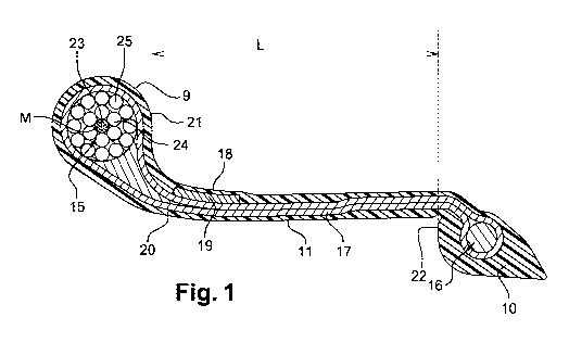
assembly in the event of impacts with kerbs or holes in the roadway, such as
potholes.
[0006] Specifically, the adapter of the above-referenced prior art, which
ensures
connection between each bead of the tyre and the rim, does not have optimum
mechanical features, chiefly in terms of stiffness, that make it possible to
absorb large
deformations as the rolling assembly passes over potholes. This may lead to
residual
to plastic deformation, even breakage, of the said adapter and,
therefore, to damage to the
rolling assembly.
[0007] In addition, this document gives no suggestion regarding adapter design
evolutions that might make it possible to overcome the aforementioned
disadvantages.
[0008] So, the inventors set themselves the objective of proposing a new
adapter that is
more resistant to impacts when the rolling assembly is used on roads in poor
condition,
while at the same time maintaining a high level of performance of the rolling
assembly
with regard to roadholding, in particular its ability to sustain high drift
thrusts.
[0009] The subject of the invention is therefore an adapter for a rolling
assembly having
an axis of rotation,
the rolling assembly comprising a tyre having two beads, a rim with two rim
bead seats
and, for each bead, the said adapter providing the connection between the bead
and the
rim,
the said adapter comprising:
- an axially inner end comprising an inner reinforcing
element and intended to
be mounted on a rim bead seat,
2015 Pat 000 72 WO
,
, CA 02984850 2017-11-02
3
- an axially outer end comprising an outer reinforcing element and intended
to
come into contact, via a substantially radial axially inner face, or bearing
face,
with a bead,
- a body connecting the axially outer end to the axially inner end so as to
form a
single piece, and comprising at least one main reinforcement providing the
connection between the outer reinforcing element and the inner reinforcing
element, and comprising a substantially axial adapter seat intended to come
into contact with a bead,
the outer reinforcing element being positioned wholly axially on the outside
of the
bearing face,
the outer reinforcing element being an annular structure, referred to as a
bead wire,
having a mean line and being made up of a stack of at least three layers made
up of metal
threads and concentric with respect to the mean line,
a first layer or core comprising at least one metal thread having a diameter
D1 at least
equal to 0.8 mm and at most equal to 5 mm,
a second layer being made up of a metal thread having a diameter D2 at most
equal to 1.4
times the diameter D1 and wound in a helix around the core forming, with the
mean line
of the bead wire, an angle A2 at least equal to 2 and at most equal to 100
,
and a third layer being made up of a metal thread having a diameter D3 and
wound in a
helix around the second layer forming, with the mean line of the bead wire, an
angle A3
at least equal to 2 and at most equal to 100, and of opposite sign to that of
the angle A2.
[0010] An adapter, the element connecting tyre and rim, allows a rolling
assembly,
during rolling, to have sufficient radial deformations at the bead of the tyre
to afford the
desired protection against lateral impacts.
[0011] The axially outer end of the adapter axially delimits a portion of the
adapter body,
referred to as adapter seat, and intended to receive a tyre bead. The adapter
seat performs
the same function as a rim seat, which is the substantially axial portion of a
rim bead seat.
In the axial direction, the bearing face of the axially outer end serves to
support the bead
2015 Pat 000 72 WO
CA 02984850 2017-11-02
4
of the tyre in the manner of a rim flange, which is the substantially radial
portion of a rim
bead seat. The tyre is therefore axially immobilized by the inflation pressure
and is
pressed firmly against the bearing face of this axially outer end, in the
manner of what
happens conventionally in the case of a bead of a tyre pressed against a rim
flange.
[0012] The axially inner end of the adapter could be termed an "adapter bead"
since it is
intended to attach the adapter to the seat of a rim bead in the same way as is
conventionally done by the bead of a tyre pressed against a rim bead seat.
[0013] Thus, while in use, the tyre is practically axially immobilized with
respect to the
rim. More specifically, the beads of the tyre are axially immobilized with
respect to the
rim, like with a conventional rolling assembly in which the beads of the tyre
are mounted
directly on the rim bead seats. By contrast, the beads of the tyre are not
immobilized
radially with respect to the rim. More specifically, the beads of the tyre
have the
possibility of moving radially with respect to the rim. Under standard running
conditions,
the axial deformation of the adapter is negligible with respect to its radial
deformation.
On the other hand, during an impact, the axial deformation of the adapter can
be great,
thereby contributing to reducing the mechanical loadings on the rolling
assembly.
[0014] The adapter according to the invention is essentially characterized by
an axially
outer end the reinforcing element of which is primarily arranged radially on
the outside of
the adapter seat. Secondly, the outer reinforcing element of the axially outer
end is an
annular structure, referred to as a bead wire, having a mean line and being
made up of a
stack of at least three layers made up of metal threads and concentric with
respect to the
mean line. By definition, the mean line of the bead wire is the locus of the
centres of
mass of the successive sections of the bead wire, namely the locus of the
centres of the
circles in the case of circular cross sections. A first layer or core of the
bead wire, which
is radially the innermost layer, comprises at least one metal thread having a
diameter D1
at least equal to 0.8 mm and at most equal to 5 mm. A second layer of the bead
wire is
made up of a metal thread having a diameter D2 at most equal to 1.4 times the
diameter
2015 Pat 000 72 WO
CA 02984850 2017-11-02
DI and wound in a helix around the core forming, with the mean line of the
bead wire, an
angle A2 at least equal to 20 and at most equal to 100. A third layer of the
bead wire is
made up of a metal thread having a diameter D3 and wound in a helix around the
second
layer forming, with the mean line of the bead wire, an angle A3 at least equal
to 2 and at
most equal to 10 , and of opposite sign to that of the angle A2.
[0015] Thus, each of the second and third layers of the bead wire is produced
by the
helical winding of a single thread. The helical windings of the threads that
respectably
make up the second and third layers of the bead wire are performed in opposite
directions
of rotation and constitute what is referred to as a twist. The twist has the
advantage of
creating natural and lasting cohesion between the threads, thanks to a
constant orientation
of the helical curvature of each thread of the layer with respect to the mean
line of the
bead wire.
[0016] Furthermore, for a given layer, the use of a single thread makes it
possible to limit
the discontinuity of the layer to its two circumferential ends only and makes
the annular
structure of the bead wire easier to produce by simply butting the
circumferential ends of
the layers together.
[00171 The main advantage of the adapter according to the invention is that it
improves
the mechanical strength of the rolling assembly, subjected to harsh road use,
through
greater deformability of the adapter, particularly greater axial
deformability. This
deformability is obtained through the optimization of the flexibility or
suppleness of the
axially outer end of the adapter, and in particular through the optimization
of the
flexibility of the outer reinforcing element. This flexibility is effectively
permitted by a
twisted bead wire which is able to deform at the same time in tension, in
compression,
and in bending.
[0018] Moreover, the adapter according to the invention has the advantage of
significantly reducing the level of mechanical load transmitted to the chassis
of the
vehicle in the event of an impact, and thus of making it possible to make the
bodyshell of
2015 Pat 000 72 WO
CA 02984850 2017-11-02
6
the vehicle lighter. Finally, the adapter according to the invention has the
advantage of
having a simple design and being easy to mount on the rolling assembly.
[0019] According to one preferred embodiment, the core of the bead wire is
made up of a
single metal thread. This single straight metal thread acts as a support for
the helical
winding of the second layer.
[0020] Again as a preference, the third layer of the bead wire is made up of a
metal
thread having a diameter D3 equal to the diameter D2. Having the same diameter
for the
threads that respectively make up the second and third layer of the bead wire
allows the
use of the same type of thread for the second and third layers, hence
simplifying
to manufacture. Furthermore, it allows the construction of bead wires
having conventional
assembly formulae.
[0021] The angles A2 and A3 formed respectively by the metal threads that make
up the
second and third layers of the bead wire are at least equal to 3 and at most
equal to 8 .
This range of angles, for the angle of each helix of the twist, makes it
possible to obtain a
curvature of the helix that is similar to the curvature of the mean line of
the bead wire.
Below the lower limit value of 3 , too small an angle gives the helix a
winding pitch,
about the core or about the inner second layer, that is too long, impairing
the cohesion of
the twist, particularly on the inside of the curvature of the bead wire, the
thread of the
layer concerned having a tendency to follow a rectilinear path with each turn
of the twist.
Above the upper limit value of 8 , too large an angle, although making it
possible to
improve the cohesion of the winding of the thread on the radially inner layer,
gives the
wire an excessive curvature, very much higher than the curvature of the mean
line of the
bead wire, the main consequence of this being a reduction in the bending
stiffness of the
bead wire.
[0022] With the second layer of the bead wire comprising, in any radial
section, N2
sections of individual threads of diameter D2, the number N2 of sections of
individual
threads of diameter D2 is at least equal to 5. Specifically, the number N2 of
sections of
2015 Pat 000 72 WO
. CA 02984850 2017-11-02
7
individual threads of the second layer of the bead wire is dependent on the
ratio between
the diameter of the winding and the diameter of the wound thread. When the
diameter D1
of the core decreases and approaches 0.7 times the value of the diameter D2 of
the thread
of the second layer, the number N2 of sections of individual threads in the
second layer
decreases and tends towards 5.
[0023] With the second layer of the bead wire comprising, in any radial
section, N2
sections of individual threads of diameter D2, and with the third layer of the
bead wire
comprising, in any radial section, N3 sections of individual threads of
diameter D3, the
number N3 of sections of individual threads of diameter D3 is at least equal
to the
number N2+6 of sections of individual threads of diameter D2. The number of
sections
of individual thread increases to a minimum of 6 at the transition from one
layer to the
layer immediately radially outside of it, when the diameters of the threads of
each layer
are equal. This increase makes it possible to achieve a sufficiently high
number of
sections of individual thread in 3 layers, for example at minimum 19 sections
of
individual thread with a single-thread core referred to as a monofilament
core, that the
bead wire achieves the necessary strength.
[0024] The diameter DI of the metal thread that makes up the core of the bead
wire is
advantageously at least equal to 1.2 mm and at most equal to 4.5 mm. Below a
minimum
value of 1.2 mm, the cross section of the thread is too small to guarantee
sufficient
stiffness of the thread, and therefore of the bead wire, meaning that the
adapter will not
be stiff enough, and this may lead to difficulties with the steering of the
rolling assembly.
Above a maximum value of 4.5 mm, the cross section of the thread is too great
to
guarantee sufficient flexibility of the thread, and therefore of the bead
wire, meaning that
the adapter will not be supple enough to absorb potential impacts to the
axially outer end
of the adapter. It should be noted that, for a metal thread based on carbon
steel which has
been strengthened by work hardening, the breaking strength of the thread
increases as the
diameter of the thread decreases.
2015 Pat 000 72 WO
CA 02984850 2017-11-02
8
[0025] With the metal threads of which the first, second and third layers of
the bead wire
are made being made of steel and having a breaking strength Rm, the breaking
strength
Rm of a steel thread is at least equal to 1000 MPa and at most equal to 3000
MPa,
preferably at least equal to 1400 MPa and at most equal to 2800 MPa. The
breaking
strength of a work-hardened steel thread generally reaches a level very much
higher than
that obtained with any other material liable to be used for the threads that
make up a bead
wire. A steel that makes it possible to achieve such a level of breaking
strength of the
threads furthermore guarantees the elastic flexibility of the bead wire,
namely reversible
flexibility of the bead wire. The reversibility of the flexible deformation of
the bead wire
subjected to an impact remains over the course of time, despite increasing
deformation of
the bead wire. The breaking strength of the steel can be increased notably by
suitable
choices relating to its chemical composition and its degree of work hardening.
[0026] With the bead wire having a circular radial cross section of diameter
Ds, the
diameter Ds of the circular radial cross section of the bead wire is at least
equal to 4 mm
and at most equal to 25 mm, preferably at least equal to 6 mm and at most
equal to 21
mm. The increase in the diameter Ds of the bead wire, and therefore in the
radial cross
section of the bead wire, makes it possible to introduce a greater number of
threads and,
therefore, to achieve the level of stiffness needed to guarantee the security
and correct
operation of the rolling assembly. The possibility of assembling an increasing
number of
threads the diameter of which can be adjusted by layer is a degree of freedom
that is
attractive from a design standpoint, particularly when the diameter Ds of the
bead wire is
limited by dimensional constraints on the expander.
[0027] According to a first embodiment of the invention, the body comprises an
annular
seat reinforcer radially on the inside of the adapter seat. However, this
annular seat
reinforcer is not compulsory.
2015 Pat 000 72 WO
CA 02984850 2017-11-02
,
9
[0028] The annular seat reinforcer advantageously has a compression modulus
greater
than or equal to 1 GPa, and preferably greater than 4 GPa, and more preferably
still,
greater than 10 GPa.
[0029] The annular seat reinforcer also advantageously comprises at least one
reinforcing
element coated in a polymer material.
[0030] According to a first alternative form of the first embodiment, the
reinforcing
element of the annular seat reinforcer comprises a metallic material such as
steel.
Usually, the reinforcing element is therefore made up of a layer or a stack of
layers of
metal cords which are collections of metal threads, the said metal cords being
coated in a
polymer, and usually elastomeric, material.
[0031] According to a second alternative form of the first embodiment, the
reinforcing
element of the annular seat reinforcer comprises a textile material such as an
aliphatic
polyamide or nylon, an aromatic polyamide or aramid, a polyester such as a
polyethylene
terephthalate (PET), or polyethylene naphthenate (PEN), or any combination of
the
aforementioned materials. Usually, the reinforcing element is made up of a
layer or a
stack of layers of textile reinforcers which are collections of spun textile
filaments, the
said textile reinforcers being coated in a polymer, and usually elastomeric,
material.
[0032] According to a third alternative form of the first embodiment, the
reinforcing
element of the annular seat reinforcer comprises glass fibres coated in a
polymer material.
[0033] According to other alternative forms of the first embodiment, the
reinforcing
element of the annular seat reinforcer may also comprise, by way of
nonlimiting
examples:
¨ carbon fibres,
¨ textile fibres other than those already mentioned: cellulose fibres such as
rayon, natural
fibres based on cotton, flax, hemp,
¨ and any combination of these fibres.
2015 Pat 000 72 WO
, CA 02984850 2017-11-02
[0034] The polymer materials that can be used for coating the reinforcing
element of the
seat reinforcer are, for example and nonlimitingly:
¨ saturated or unsaturated elastomers, potentially containing thermoplastic
blocks
(thermoplastic elastomers or TPEs),
5 ¨ thermoplastic materials,
¨ thermosetting materials.
[0035] According to a preferred alternative form of the first embodiment, the
annular seat
reinforcer is a composite material based on glass fibre coated in a
thermoplastic matrix.
In this case, the glass fibres constitute the reinforcing element of the
annular seat
to reinforcer and the coating material is the thermoplastic.
[0036] The annular seat reinforcer advantageously has an axial width at least
equal to
30% and at most equal to 150% of the axial width of the bead of the tyre, and
preferably
at least equal to 40% and at most equal to 110% of the axial width of the bead
of the tyre.
[0037] The annular seat reinforcer may more advantageously still have a mean
radial
thickness at least equal to 0.3 mm and at most equal to 20 mm, preferably
comprised
between 0.5 mm and 10 mm. This radial thickness is dependent on the size of
the tyre.
For a passenger vehicle tyre, the radial thickness is preferably between 0.5
and 10 mm.
[0038] When the reinforcing element of the annular seat reinforcer is formed
of a stack of
layers of reinforcers, the annular seat reinforcer preferably has an axial
width at least
equal to 5 mm and at most equal to 25 mm and a radial thickness at least equal
to 0.1 mm
and at most equal to 4 mm.
[0039] Each layer of reinforcers of the stack of layers of reinforcers has an
axial width at
least equal to 1 mm and at most equal to 25 mm, and a radial thickness at
least equal to
0.1 mm and at most equal to 2 mm. The axial widths and radial thicknesses of
the various
layers of reinforcers are not necessarily identical.
2015 Pat 000 72 WO
=
CA 02984850 2017-11-02
11
[0040] For preference, the annular seat reinforcer may be arranged, on the
inside of the
adapter body, radially on the outside or radially on the inside of the main
reinforcement
of the adapter body, or between the layers of the said main reinforcement,
this main
reinforcement usually comprising two layers.
[0041] According to a second embodiment of the invention, the main
reinforcement of
the body comprises a radial superposition of at least two layers of
reinforcers, the said
reinforcers being mutually parallel within one and the same layer and crossed
with one
another from one layer to the next and each of the layers of the main
reinforcement of the
body comprises reinforcers which make, with a circumferential direction of the
tyre, an
to angle at least equal to 300, and coated with a polymer material having
an elastic modulus
at 10% elongation at most equal to 70 MPa. The second embodiment of the
invention
differs essentially from the first embodiment through the absence of an
annular seat
reinforcer.
[0042] In this second embodiment, the fact that the bead wire is positioned
wholly axially
on the outside of the bearing face and therefore on the outside of the adapter
body ensures
that the bead wire does not axially stiffen the body and therefore does not
limit the axial
deformability thereof.
[0043] In addition, the main reinforcement of the body comprises a radial
superposition
of at least two layers of reinforcers, the said reinforcers being mutually
parallel within
one and the same layer and crossed with one another from one layer to the next
and each
layer is made up of reinforcers which make, with the circumferential
direction, an angle
at least equal to 30 , these reinforcers being coated with a polymer material
having an
elastic modulus at 10% elongation at most equal to 70 MPa.
[0044] The main reinforcement is, in effect, made up of the winding of a layer
of
reinforcers respectively around the outer reinforcing element and the inner
reinforcing
element. This results in a radial superposition of at least two layers in the
body: two
layers if there is no superposition of the ends of the winding, 3 layers if
there is some
2015 Pat 000 72 WO
CA 02984850 2017-11-02
12
superposition of the ends of the winding. The angle formed by the reinforcers
of a layer,
with the circumferential direction, is given in terms of absolute value in the
knowledge
that, given the principle of manufacture adopted for the main reinforcement,
the sign of
the angle reverses when passing from one layer to the next.
[0045] Having a minimum threshold value for the angle of the reinforcers
ensures the
adapter a minimal axial stiffness needed for the cornering stiffness expected
of the rolling
assembly. Having an elastic modulus at 10% elongation for the polymer coating
material
that is below a maximum threshold value guarantees the axial deformability of
the
adapter.
to [0046] The combination of the features of the second embodiment offers
the advantage
of having an adapter that is axially supple enough that it can be fitted with
ease, together
with a good ability to absorb large deformations in the event of pinch shock.
[0047] The main reinforcement of the said adapter body generally has a modulus
at least
equal to 4 GPa. It may comprise reinforcers made of all kinds of metallic or
textile
is material such as those already mentioned in respect of the annular seat
reinforcer.
[0048] The axial width of the adapter body according to the invention is
generally at least
equal to 2.54 cm and at most equal to 8 cm, and preferably at least equal to
3.17 cm and
at most equal to 5.10 cm.
[0049] For preference, the adapter may be positioned on just one side of the
rim, and
20 more preferably still, on the outboard side of the vehicle. In this
case, the rim then has an
asymmetrical geometric shape so as to adapt to the presence of the adapter
present on just
one side.
[0050] When the rolling assembly comprises two adapters, these may be
symmetrical or
non-symmetrical. The concept of symmetry or asymmetry of the adapter is
defined by the
25 axial width of the body of the adapter. Two adapters are asymmetrical
when the body of
one of them has an axial width that is greater than that of the other.
2015 Pat 000 72 WO
..
. CA 02984850 2017-11-02
13
[0051] For preference, the rolling assembly according to the invention
comprises a first
and a second adapter that each have a body of different or identical widths.
[0052] Another subject of the invention is a rolling assembly comprising, for
each bead
of the tyre, an adapter according to any one of the embodiments described
hereinabove.
[0053] The invention is described with reference to the following Figures 1 to
3, which
are schematic and not necessarily drawn to scale:
- Figure 1: a radial section of a non-mounted adapter, according to a
first
alternative form of the invention with an annular seat reinforcer;
- Figure 2: a radial section of a non-mounted adapter, according to a
second
alternative form of the invention without an annular seat reinforcer;
- Figure 3: a radial section of a rolling assembly, comprising two adapters
according to the second alternative form of the invention without an annular
seat reinforcer.
[0054] Figure 1 depicts an adapter, not mounted on a rim, according to a first
alternative
form of the invention with an annular seat reinforcer. This adapter comprises
an axially
outer end 9 comprising an outer reinforcing element 15, an axially inner end
10
comprising an inner reinforcing element 16, and a body 11 comprising a main
reinforcement 17. The main reinforcement 17 is made up of a single reinforcing
layer
which is wound respectively around the inner reinforcing element 16 of the
axially inner
end 10 and around the outer reinforcing element 15 of the axially outer end 9.
In the body
11, the main and return portions of the said reinforcing layer thus constitute
a
substantially radial stack of at least two reinforcing layers. The main
reinforcement 17 is
enveloped in a layer of elastomeric material 20. The body 11 further comprises
an adapter
seat 18 which is intended to come into contact with a tyre bead. The body 11
has axial
width L, measured between the axially inner face 21 of the axially outer end 9
and the
axially outer face 26 of the axially inner end 10. In this first embodiment of
the invention,
the body 11 also comprises an annular seat reinforcer 19 radially on the
outside of the
main reinforcement 17 and axially on the inside of the axially outer end 9.
2015 Pat 000 72 WO
CA 02984850 2017-11-02
14
[0055] In Figure 1, the outer reinforcing element 15 is an annular structure,
referred to as
a bead wire, having a mean line M and made up of a stack of three layers (23,
24, 25)
made up of metal wires and concentric with respect to the mean line M. The
first layer or
core 23, which is radially the innermost layer, comprises at least one metal
thread having
a diameter DI at least equal to 0.8 mm and at most equal to 5 mm. The second
layer 24 is
made up of a metal thread having a diameter D2 equal, in the instance
depicted, to the
diameter D1 and wound in a helix around the core 23, forming, with the mean
line M of
the bead wire 15, an angle A2 (not depicted) at least equal to 2 and at most
equal to 100
.
The third layer 25 is made up of a metal thread having a diameter D3 equal, in
the
instance depicted, to the diameter D2 and wound in a helix around the second
layer 24,
forming, with the mean line M of the bead wire 15, an angle A3 (not depicted)
at least
equal to 2 and at most equal to 10 , and of opposite sign to that of the
angle A2. In the
instance depicted, the core is made up of a single metal thread, the second
layer 24 has a
number N2 of sections of individual thread equal to 6, and the third layer 25
has a
number N3 of sections of individual thread equal to 12.
100561 Figure 2 differs from Figure 1 only in the omission of the annular seat
reinforcer
(19).
[0057] Figure 3 shows a radial section, in a plane YZ, of a rolling assembly
comprising a
tyre P, a rim J, and, for each bead B, an adapter A providing the connection
between the
bead B and the rim J. The tyre P comprises a tread (unreferenced) extended
radially
towards the inside by two sidewalls 1, themselves extended radially towards
the inside by
two beads B. Within each bead B, the carcass reinforcement 2 is turned up
around a
circumferential reinforcing element or bead wire 3 to form a turnup 4
separated from the
carcass reinforcement 2 by a filling element 5. The rim J comprises, in a
middle portion,
a mounting well 6, intended to make it easier to mount the beads B of the tyre
P and, at
its axial ends, two rim bead seats 8, each one comprising a substantially
radial portion or
rim flange 7a and substantially axial portion or rim seat 7b. The adapter A
comprises a
radially inner end 10 comprising an inner reinforcing element 16 and intended
to be
2015 Pat 000 72 WO
, CA 02984850 2017-11-02
mounted on a rim bead seat 8, an axially outer end 9 comprising an outer
reinforcing
element 15 and intended to come into contact via a substantially radial
axially inner face
or bearing face 21 with a bead B, and finally a body 11, connecting the
axially outer end
9 to the axially inner end 10 so as to form a single piece, and comprising at
least one
5 main reinforcement 17 providing the connection between the outer
reinforcing element
15 and the inner reinforcing element 16, and comprising a substantially axial
adapter seat
18 intended to come into contact with a bead B.
[0058] By way of illustration, two examples of bead wires were evaluated as
adapter
outer reinforcing element 15.
10 [0059] The first example is a bead wire made up of 3 layers of
steel reinforcers. The
radially innermost first layer or core 23 comprises a metal thread having a
diameter DI
equal to 3 mm. The second layer 24 is made up of a metal thread having a
diameter D2
equal to 1.75 mm and wound in a helix around the core 23, forming, with the
mean line
M of the bead wire 15, an angle A2 (not depicted) equal to 6.2 . The third
layer 25 is
15 made up of a metal thread having a diameter D3 equal to the
diameter D2, namely to 1.75
mm, and wound in a helix around the second layer 24, forming, with the mean
line M of
the bead wire 15, an angle A3 (not depicted) equal to 8.8 , and of opposite
sign to that of
the angle A2. In this instance, the second layer 24 has a number N2 of
sections of
individual thread equal to 8, and the third layer 25 has a number N3 of
sections of
individual thread equal to 14. The formula for this bead wire is therefore 1*3
mm +
8*1.75 mm + 14*1.75 mm.
[0060] The second example, corresponding to the scenario illustrated in
Figures 2 and 3,
is a bead wire made up of 3 layers of steel reinforcers. The radially
innermost first layer
or core 23 comprises a metal thread having a diameter D1 equal to 2 mm. The
second
layer 24 is made up of a metal thread having a diameter D2 equal to the
diameter 131,
namely to 2 mm and wound in a helix around the core 23, forming, with the mean
line M
of the bead wire 15, an angle A2 (not depicted) equal to 3.3 . The third layer
25 is made
up of a metal thread having a diameter D3 equal to the diameter D2, namely to
2 mm, and
2015 Pat 000 72 WO
CA 02984850 2017-11-02
16
wound in a helix around the second layer 24, forming, with the mean line M of
the bead
wire 15, an angle A3 (not depicted) equal to 6.6 , and of opposite sign to
that of the angle
A2. In this instance, the second layer 24 has a number N2 of sections of
individual thread
equal to 6, and the third layer 25 has a number N3 of sections of individual
thread equal
to 12. The formula for this bead wire is therefore (1 + 6 + 12)*2 mm.
[0061] The first example of bead wire of formula (1*3 mm + 8*1.75 mm + 14*1.75
mm)
was incorporated into an adapter for a tyre of size 225/45R17 mounted on a
4.5B16
wheel. Furthermore, this bead wire has a toric shape with an inside diameter
equal to 471
mm and a mass equal to 713 g. This rolling assembly Si, comprising two
adapters (one
to adapter per bead), was compared on the one hand against a standard
reference rolling
assembly R1 with no adapter, comprising a tyre of size 225/45R17 mounted on a
7.5J17
wheel, and, on the other hand, against a rolling assembly El comprising a tyre
of size
225/45R17 mounted on a 7.5J17 wheel, and two adapters (one adapter per bead).
Each
adapter of the rolling assembly El has, as outer reinforcing element, a solid
bead wire the
radial cross section of which is a disc of diameter 10 mm and the constituent
material of
which is a glass - resin composite, namely one containing glass fibres in a
resin matrix.
[0062] For each of the three rolling assemblies Si, R1 and El described
hereinabove, the
cornering stiffness DZ and the radial stiffness KZ were measured. The
cornering stiffness
DZ, expressed in daN/ , is the axial force that has to be applied to the tyre
in order to
generate a 1 rotation of the rolling assembly about a radial axis. In this
instance, the
cornering stiffness DZ is measured for a tyre inflated to a pressure equal to
2.5 bar and
compressed under a radial load Z equal to 4286 N. The radial stiffness KZ,
expressed in
daN/mm, is the radial force that has to be applied to the tyre in order to
obtain a radial
movement of 1 mm. In this instance, the radial stiffness KZ is measured for a
tyre
inflated to a pressure P equal to 2.5 bar, its nominal load Z, within the
meaning of the
ETRTO (European Tyre and Rim Technical Organization) standard, being equal to
3620
daN. In the table below, the cornering stiffness DZ and radial stiffness KZ of
the tyres of
2015 Pat 000 72 WO
CA 02984850 2017-11-02
17
the rolling assemblies Si, RI and El compared are expressed in the form of a
relative
value with respect to reference rolling assembly R1, considered as the base
100.
[0063] Furthermore, the three rolling assemblies S1 , RI and El were subjected
to a
"pinch shock" test, followed by an endurance test. A "pinch shock" test
consists in
subjecting the tyre, inflated to a pressure P equal to 2.3 bar, compressed
under a load Z
equal to 500 daN and running at 45 km/h, to repeated impacts against a kerb
110 mm
high, in a direction that makes an angle equal to 70 with respect to the
direction of
travel. At the end of this "pinch shock" test, an endurance test is performed
in which the
tyre, running at 30 km/h, is subjected to cornering angles varying between -6
and +6
about the radial direction. The integrity of the tyre is then examined at the
end of this
sequence of two tests.
[0064] Table 1 hereinbelow presents the results of cornering stiffness DZ,
radial stiffness
KZ and cornering endurance test following a "pinch shock" test for the rolling
assemblies
RI, El and S1 for a tyre of size 225/45R17:
Rolling assembly Cornering Radial stiffness Integrity in cornering
stiffness DZ KZ endurance after
(Z=4826N, (Z=3620N, "pinch shock" test
P= 2.5bar) P= 2.5bar)
RI : Tyre 225/45R17 + 100% 100% NA (puncture)
wheel 7.5J17
El: Tyre 225/45R17 + 2 adapters 96% 98% NOK (bead wire
with external bead wire made of CVR breakage)
(diam. ext 10 mm) + wheel 4.5B16
S I: Tyre 225/45R17 +2 adapters 97% 98% OK
with external bead wire of formula
(1*3mm + 8*1.75mm + 14*1.75mm -
diam. ext lOmm) + wheel 4.5B16
Table 1: Cornering stiffness, radial stiffness and endurance on 225/45R17
2015 Pat 000 72 WO
CA 02984850 2017-11-02
18
[0065] Table 1 shows that the two rolling assemblies El and S1 with adapters
have
cornering stiffnesses DZ and radial stiffnesses KZ of substantially the same
magnitude as
those of the reference rolling assembly RI without adapter. By contrast,
rolling assembly
SI performs better than rolling assembly DI in the endurance test after the
"pinch shock"
test because the adapter bead wire remains intact for S1 whereas the adapter
bead wire for
El has broken.
[0066] Table 2 below shows the same type of results for three rolling
assemblies R2, S21
and S22 in the case of a tyre of size 245/40R18. The standard reference
rolling assembly
R2, without adapter, comprises a tyre of size 245/40R18 mounted on a 8J17
wheel. The
rolling assembly S21 comprises a tyre of size 245/40R18 mounted on a 4.5J16
wheel,
and two adapters (one adapter per bead). Each adapter of the rolling assembly
S21 has, as
outer reinforcing element, a bead wire of formula (1*3 mm + 8*1.75 mm +
14*1.75 mm)
the circular radial cross section of which has a diameter equal to 10 mm. The
rolling
assembly S22 comprises a tyre of size 245/40R18 mounted on a 4.5J16 wheel, and
two
adapters (one adapter per bead). Each adapter of the rolling assembly S22 has,
as outer
reinforcing element, a bead wire of formula (1 + 6 + 12)*2 mm the circular
radial cross
section of which has a diameter of 10 mm. Furthermore, this bead wire has a
tone shape
with an inside diameter equal to 471 mm and a mass equal to 707 g.
[0067] Table 2 below presents the results of cornering stiffness DZ, radial
stiffness KZ
and cornering endurance test following a "pinch shock" test for the rolling
assemblies
R2, S21 and S22 for a tyre of size 245/40R18:
2015 Pat 000 72 WO
CA 02984850 2017-11-02
19
Rolling assembly Cornering Radial stiffness Integrity in cornering
stiffness DZ KZ endurance after
(Z=5101N, (Z=3826N, "pinch shock" test
P= 2.5bar) P= 2.5bar)
R2 : Tyre 245/40R18 + 100% 100% NA (puncture)
wheel 8J17
S21 : Tyre 245/40R18 + 2 adapters 99% 99% OK
with external bead wire of formula
(1*3mm + 8*1.75mm + 14*1.75mm -
diam. ext lOmm) + wheel 4.5J16
S22 : Tyre 245/40R18 + 2 adapters 98% 99% OK
with external bead wire of formula
(1+6 + 12)*2 mm avec diam. ext
lOmm) + wheel 4.5J16
Table 2: Cornering stiffness, radial stiffness and endurance on 245/40R18
[0068] Table 2 shows that the two rolling assemblies S21 and S22 with adapters
have
cornering stiffnesses DZ and radial stiffnesses KZ of substantially the same
magnitude as
those of the reference rolling assembly R2 without adapter. In addition, the
two rolling
assemblies S21 and S22 both pass the endurance test following a "pinch shock"
test.
2015 Pat 000 72 WO