Note : Les descriptions sont présentées dans la langue officielle dans laquelle elles ont été soumises.
-1-
10
Aircraft door arrangement with sound reduced hollow space which can be covered
by an aircraft door
TECHNICAL FIELD
The invention relates to an aircraft door arrangement with a hollow space
which can
be covered by an aircraft door and at least one sound reducing profile body
arranged
in the hollow space and to an aircraft with a fuselage, a door opening
arranged
therein and an aircraft door arrangement assigned to the door opening.
BACKGROUND OF THE INVENTION
Doors for closing an opening of a fuselage of a commercial aircraft typically
consist
of a reinforced, areal component which is designed such that the door
preferably
forms an even, continuous (step less) surface with the outer surface of the
fuselage in
the closed state of the door. The structure used for reinforcement extensively
extends
along the inner surface of the door and is inspired in its formation by a
fuselage
structure and comprises stringer and cross-bracing elements which are
connected to
the outer skin.
An edge region extending close to the outer edge of the inner surface of the
door is
provided with a door seal which seals the interior of the fuselage with
respect to the
surrounding if the door is closed Typically, the door seal directly rests on
the inner
Date Recue/Date Received 2022-09-22
CA 02995138 2018-02-08
WO 2017/029180 PCT/EP2016/069105
- 2 -
surface of the areal component and has a sealing profile which is vaulted and
supported by supporting profiles. In the closed state of the door, the sealing
profile
clings to a corresponding sealing surface in or at the door opening and is
thereby
compressed to a flush sealing. A hollow space is created between an opening
contour, an outer edge of the door, the sealing profile and the seal seat, in
which
hollow space flow-induced resonance effects may arise. Often, the hollow space
may
be considered a "deep hollow space" which has a low width in the profile cross
section in comparison to the direction of extension of the gap.
US 2012/0267475 Al describes an acoustic sealing arrangement which extends
along a gap in an aircraft door arrangement, which acoustic sealing
arrangement fills
a hollow space being formed between the aircraft door and a frame located at a
door
opening and consists of a sound reducing material as to reduce wind noises.
SUMMARY OF THE INVENTION
It may be understood as an object of the invention to propose an aircraft door
at
which flow-induced resonance effects may be reduced or completely eliminated
without having to make modifications to the seal or, generally, to the door
structure.
This object is solved by an aircraft door arrangement with the features of the
independent claim 1. Advantageous embodiments and improvements can be taken
from the dependent claims and the following description.
An aircraft door arrangement for an aircraft fuselage is proposed, the
aircraft door
arrangement comprising an aircraft door, at least one door seal arranged at an
inner side of the aircraft door and extending circumferentially in an edge
region
of the aircraft door and a door opening closable by the aircraft door which
door
opening has an opening edge adjoining to the opening and extending to the
interior of the aircraft fuselage at which opening edge a seal seat is
arranged
which can be brought into a flush contact with the door seal. A hollow space
is
formed by the door seal, the seal seat and the opening edge, which hollow
space
may at least partially be covered by the aircraft door. A gap is connected
with the
CA 02995138 2018-02-08
WO 2017/029180
PCT/EP2016/069105
- 3 -
hollow space, which gap is located between the aircraft door and the door
opening
if the aircraft door is closed. One substantial feature is that at least one
sound
reducing profile is arranged at the opening edge in the hollow space, which
sound
reducing profile comprises at least one planar surface section which is
oriented
oblique with respect to a surface of the aircraft door which surface is
adjacent to
the gap, wherein the surface section at least partially follows the course of
the
gap.
The air within the hollow space which is fluidically connected to the
surrounding
via the gap may be excited to vibrations by flowing. A perceivable noise which
is
to be dampened arises depending on the size of the gap, the size and
orientation of
the gap, the presence of a step between the aircraft door and the edge region
of
the door opening. Integration of at least one sound reducing profile according
to
the abovementioned implementation may result in a substantial reduction of the
noise without any modification of the aircraft door or of a region around a
door
opening. The at least one planar surface section which is arranged in the
hollow
space oblique with respect to the direction of extension of the sound waves
influences the direction of propagation and the reflection of the sound waves
in
the hollow space in such a manner that the noise generation is reduced. For
example, the at least one planar surface section may reflect impinging sound
waves in a direction facing away from the gap, as a consequence of which the
sound waves may diminish in the hollow space. Multiple reflection which occurs
in the hollow space may result in multiple change of direction which converts
the
kinetic energy of the sound waves into other forms of energy and, hence,
reduces
noise generation. However, depending on the material selection, contour design
and orientation, the at least one planar surface section may also interfere
with the
sound propagation in another manner, like sound absorption, sound transmission
or sound dissipation.
Here, the sound reducing profiles are preferably elongated, stripe-like bodies
which have a certain uniform profile cross section or, if desired, a profile
cross
section varying along its circumference and which can be adhered or inserted
CA 02995138 2018-02-08
WO 2017/029180
PCT/EP2016/069105
- 4 -
along the opening edge which typically is freely available. Hence, the sound
reducing profile is very easy to be inserted into already existing aircraft
door
arrangements and provides a very good retrofit solution for considerable sound
reduction. Modifications are not required.
If the door provides enough space between its edge and the door seal, the
arrangement of the sound reducing profiles may also be located at the door on
the
opening edge and may extend along the opening edge, wherein this location
information is to be understood when the door is closed.
In an advantageous embodiment, multiple sound reducing profiles which are
adjacent to each other are arranged in the hollow space. Here, an adjacent
arrangement refers to the arrangement of multiple sound reducing profiles in
the
hollow space, which sound reducing profiles follow upon one another from the
gap in a direction towards a center of the door. Consequently, the entire
planar
surface section which can be provided thereby is large, or, depending on the
number of the used sound reducing profiles, very large in comparison to a
single
sound reducing profile and the sound reduction may be further improved as a
result of this. Depending on the type of the used material of the sound
reducing
profile, the additional weight is small or negligible. A preferred combination
results from four sound reducing profiles.
Of the adjacent sound reducing profiles there are at least two sound reducing
profiles adjacent directly to each other and do not have any distance to each
other.
Consequently, two or more planar surface sections follow directly one after
another and may form a step-like structure. The sound reduction achieved
thereby
is considerably improved due to the greater area.
For achieving the inventive advantages, it is preferred that the planar
surface
section is at an angle in a range from 5 to 60 with respect to the surface
of the
aircraft door, which surface is adjacent to the gap. This surface is to be
considered
CA 02995138 2018-02-08
WO 2017/029180
PCT/EP2016/069105
- 5 -
as the outer skin surface of the aircraft fuselage or of the door which
directly
adjoins the gap.
Additionally, the basis may also have an angle in a range from 50 to 600 with
respect to the surface of the aircraft door adjacent to the gap. Preferably,
this
angle falls short of the previously mentioned angle of the planar surface
section
so that a mandrel-like profile cross section is the result. At least in an
ending
region, this may additionally be bent in a direction facing towards the gap.
The individual height of the single sound reducing profiles may be adapted to
the
geometry of the hollow space so that these may have different heights. The
maximum extension of each of the single sound reducing profiles from the
opening edge in direction towards the door seal, i.e., the length of the
single
"spikes" of the sound reducing profile, may increase with increasing distance
from the gap. Thus, each of multiple planar surface sections following one
after
another may reflect a part of the sound waves which propagate in the hollow
space and which are directed to the single planar surfaces and collectively
contribute to a sound reflection. A region further protruding to the door seal
is
covered by each planar surface section due to the increasing extension,
wherein
the individual sections which belong to the sound reducing profiles may also
overlap each other.
The width of a sound reducing profile which width is measured cross to the
outer
surface in an edge region of the door opening, i.e., from the gap in a
direction
towards the interior of the fuselage, is dependent from the angle of the
planar
surface section and the extension of the sound reducing profile towards the
door
seal. If only one section of the sound reducing profile, which section is
close to
the door seal, is equipped with a planar surface section, the width may be
chosen
relatively small which may result in increasing the possible number of sound
reducing profiles. On the other hand, the entire extension of the sound
reducing
profile which faces towards the door seal may be used for arranging the planar
surface section so that the individual planar surface sections are designed
greatest
CA 02995138 2018-02-08
WO 2017/029180
PCT/EP2016/069105
- 6 -
possible, wherein this may increase the required widths of the sound reducing
profiles. It may be considered to be advantageous to design an arrangement of
sound reducing profiles, which sound reducing profiles are adjacent to each
other,
such that the arrangement extends along at least half of the depth of the
hollow
space, which depth is measured starting from the gap to an opposite end of the
hollow space.
The maximum extension of the at least one sound reducing profile from the
opening edge towards the door seal may be chosen such that the door seal is
not
touched reliably, while at the same time with at least one of the sound
reducing
profiles a greatest possible extension towards the door seal and, thus, a
greatest
possible planar surface section is ensured. The achievable width of a sound
reducing profile measured in this direction may be about in a range which
includes 75% to 95% and preferably 90% to 95% of the available local clear
span
of a surface in the hollow space suitable for the integration of a sound
reducing
profile.
The at least one sound reducing profile may be made of a hydrophobic and
temperature-resistant material which results in an adequate form stability.
Especially suitable is silicone, an elastomer or another rubber-like material.
The at least one sound reducing profile may be made of a foam material which
preferably is open-celled, but nevertheless may be sufficiently dimensionally
stable. Due to the open-celled design, a sound absorption may take place
additionally to the sound reflection which results in conversion of the
kinetic
energy of the sound waves into other forms of energy as soon as the foam
material is passed. As a matter of course, the foam material may also be close-
celled which positively influence the dimensional stability. Manufacturing of
a
foam material results in an advantageously low weight as a majority of the
volume is filled by a gas.
CA 02995138 2018-02-08
WO 2017/029180
PCT/EP2016/069105
- 7 -
It is furthermore conceivable that the sound reducing profile alternatively
consists
of an extruded plastic which in particular simplifies the fabrication
considerably.
Such a plastic may comprise dimensionally stable, rigid plastics as well as
supple
and rubber-like plastics. Alternatively, using of materials on the basis of
natural
origin, as for example rubber, is also possible.
The sound reducing profile may further additionally comprise a layer of a
carrier
material which differs from the main material of the sound reducing profile.
The
carrier material may be adapted for connection of the sound reducing profile,
while a region carrying the planar surface section may be adapted to the sound
characteristics.
In case multiple sound reducing profiles are used side by side, these may also
be
fabricated as a single part in the form of a single and continuous stripe.
This
facilitates the attachment of the sound reducing profiles considerably as a
separate
positioning of sound reducing profiles which are spaced apart from each other
is
omitted.
For ease of attachment it makes sense that the at least one sound reducing
profile
comprises an adhesive or mechanic connection means which is tolerant with
respect to the environmental influences, i.e., changes in pressure, a wide
temperature range, humidity and fuselage deformations. For example, a self-
adhesive support area may be provided, alternatively also pin connections,
screw
connections, rivet connections may be used or an adhesive based, for example,
on
a suitable resin may be applied as to thereby fasten the sound reducing
profile.
The invention further relates to an aircraft comprising an aircraft fuselage
with at
least one previously described aircraft door arrangement. The sound reducing
profile may follow at least a majority of the course of the gap along lateral
sections of the aircraft door which progress vertical to a flight direction,
at which
lateral section the noise generation is at its maximum due to the flight
direction
progressing perpendicular thereto. Especially advantageously, the sound
reducing
CA 02995138 2018-02-08
WO 2017/029180 PCT/EP2016/069105
- 8 -
profile is affixed from an upper to a lower door radius, wherein this may
include
the door radius at least in part.
BRIEF DESCRIPTION OF THE DRAWINGS
Further features, advantages and application possibilities of the present
invention can
be derived from the following description of exemplary embodiments and the
drawings. Thereby, all described and/or visually depicted features for
themselves and
in any combination form the subject matter of the invention independent of
their
combination in the individual claims or their dependencies. In the drawings,
same
reference signs indicate same or similar objects.
Fig. 1 shows a sectional view of an exemplary aircraft door arrangement.
Fig. 2 shows an aircraft door with a section position marked therein.
Fig. 3 shows an exemplary noise spectrum with a reduction of a tonal noise.
DETAILED DESCRIPTION OF EXEMPLARY EMBODIMENTS
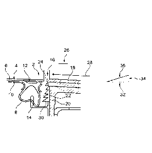
In Fig. 1, a section through a lateral door sealing region of an aircraft door
arrangement 2 is shown. Exemplarily, a section surface can be seen which is
oriented
vertically upwards, that is, in negative Z-direction of a coordinate system
defined
with respect to the aircraft. For clarification, the location and the section
direction are
shown in Fig. 2.
The aircraft door arrangement 2 comprises an aircraft door 4 which comprises
an
areal reinforced component 6 that has a vaulted, compressible sealing profile
8 which
is held in a predefined shape by retaining plates 10 and 12. The sealing
profile 8
extends from the door component 6 inwardly in a direction towards the interior
of the
fuselage which is arranged at a side of the sealing profile 8 which faces away
from
the reinforced component 6 at least in the closed state of the door 4. In a
closed state
of the door 4, the sealing profile 8 is pressed onto a seal seat 14 as to
cause a sealing
CA 02995138 2018-02-08
WO 2017/029180 PCT/EP2016/069105
- 9 -
effect there. Then, the door 4 closes a door opening 16 as flush as possible
as to
provide an outer surface at an aircraft fuselage 18 as harmonic as possible.
Due to the design, in the closed state a hollow space 22 is formed between the
seal
seat 14, the sealing profile 8, the contours of the opening 16 and one or more
reinforcement components 20 of the fuselage 18 which protrude towards the
sealing
profile 8, which hollow space is in fluidic connection with the surrounding
via a gap
24 between the door component 6 and contours of the opening 16. Due to
fabrication
tolerances, thermal expansion effects and the like, a step 26 may be present
between
the door component 6 and the adjacent surface of the fuselage 18. During
flight, air
flows with a relatively high speed exemplarily in a direction indicated by the
arrow
28 via the gap 24 or the step 26 so that resonance effects and, thus, noises
caused
thereby arise. This may, in particular, be noticed at a lateral boundary of
the door as
there a direct overflow of the gap 24 or the step 26 happens perpendicular to
its
extension. Depending on the dimension of the hollow space 22 and the profiling
of
the opening 20 as well as of the door component 6, tonal noises may arise
every now
and then, which in the worst case perceivably extend into the passenger cabin
of the
aircraft via structure-born sound.
The type and, in particular, the frequency of the tonal noise may be
determined in
part by the general shape of the hollow space 22. In the shown case, the
extension of
the hollow space along the direction of flow 28 is substantially lower than
perpendicular thereto, i.e., in direction of the seal seat 14. The hollow
space 22 is to
be considered as a "deep" hollow space 22 in this exemplary embodiment.
For reducing or completely eliminating this noise, multiple sound reducing
profiles
are arranged side by side and following the extension of the gap 24, wherein
the
sound reducing profiles are arranged at a side of the structural component 20
facing
towards the sealing profile 8, and which sound reducing profiles exemplarily
have a
30 triangular cross section. The cross section comprises a basis 32,
respectively, which
is exemplarily arranged parallel to the gap 24 or to the surface of the door 4
or of the
fuselage 18 adjacent to the gap 24 or parallel to the direction of flow 28.
Thereto, a
CA 02995138 2018-02-08
WO 2017/029180 PCT/EP2016/069105
- 10 -
support area 34 is adjoined, which support area is about perpendicularly
extending in
this example and which support area is connected to the structural component
20 by
adhesion, for example. A planar surface section 36 extends between the basis
32 and
the support area 34, which surface section extends oblique at an angle a with
respect
to the local direction of extension of the door component 6 or the adjoining
surface
of the fuselage 18. It is the aim of this forming that the propagation of
pressure
waves is disrupted, which pressure waves move through the gap 24 into the
hollow
space 22 and are obliquely reflected at the planar surface sections 36 with
respect to
the initial direction of propagation. Thus, the feedback and, as a
consequence,
resonance conditions are impaired.
It may make sense to choose a larger extension of the structural component 20
into
the hollow space 22 with increasing distance from the gap 24. Specifically,
with the
arrangement of multiple sound reducing profiles 30 side by side this means
that these
evolve from a relatively small extension of the basis 32 directly below the
gap 24 to
a considerably enlarged extension of the basis 32 at an opposite end of the
hollow
space 22.
The width of the individual sound reducing profiles 30, that is the
longitudinal
extension of the support area 34 along the structural component 20 in the
sectional
view, may be the same at all sound reducing profiles 30 so that the angle a of
each
planar surface section 36 may decrease with increasing distance from the gap
24.
However, this is not necessary, alternatively also a uniform angle may be
chosen so
that the extension of the support area 34 in the sectional view is enlarged
with
increasing sound reducing profile 30 or so that the planar surface section 36
is offset
towards the sealing profile 8.
Further alternatively, an increasing angle may also be considered, by means of
which
the size of the support area 34 may be steadily increased or the planar
surface section
36 comprises an increasing offset with respect to the sealing profile 8.
CA 02995138 2018-02-08
WO 2017/029180 PCT/EP2016/069105
- 11 -
For further improvement of the sound insulation properties, single or all
basal planes
32 may likewise extend angularly with respect to the surface of the door 4 or
of the
fuselage 18, which surface adjoins the gap 24 or with respect to the direction
of flow
28 resulting in a mandrel-like shape of the sound reducing profiles formed
thereby.
Fig. 2 shows a schematic representation of the aircraft door 4 and the opening
16 as
well as exemplarily the position where the sectional view shown in Fig. 1
originates
from. As the gap 24 is overflown cross almost exclusively at lateral surfaces
of the
aircraft door 4, integration of the sound reducing profiles 30 is suitable in
particular
there.
Fig. 3 exemplarily shows a noise spectrum from which the sound pressure can be
read on the vertical axis and the frequency can be read on the horizontal
axis. An
upper curve 38 represents an unchanged noise spectrum without usage of sound
reducing profiles 30, which upper curve in particular comprises a relatively
discrete
tonal noise in a marked region 40. In particular, the frequency is dependent
from the
design of the hollow space 22 here. In a lower curve 42 set below, the noise
damped
by using the inventive sound reducing profiles 30 is shown, at which noise
also the
initial tonal share is missing.
Additionally, it is noted that "comprising" does not exclude any other
elements and
"a" or "an" does not exclude a plurality. It is further noted that features
which are
described with reference to one of the above exemplary embodiments may also be
used in combination with other features of other exemplary embodiments
described
above. Reference signs in the claims are not to be construed as a limitation.