Sélection de la langue

Search

Sommaire du brevet 3010169 

Énoncé de désistement de responsabilité concernant l'information provenant de tiers

Une partie des informations de ce site Web a été fournie par des sources externes. Le gouvernement du Canada n'assume aucune responsabilité concernant la précision, l'actualité ou la fiabilité des informations fournies par les sources externes. Les utilisateurs qui désirent employer cette information devraient consulter directement la source des informations. Le contenu fourni par les sources externes n'est pas assujetti aux exigences sur les langues officielles, la protection des renseignements personnels et l'accessibilité.

Disponibilité de l'Abrégé et des Revendications

L'apparition de différences dans le texte et l'image des Revendications et de l'Abrégé dépend du moment auquel le document est publié. Les textes des Revendications et de l'Abrégé sont affichés :

  • lorsque la demande peut être examinée par le public;
  • lorsque le brevet est émis (délivrance).
(12) Brevet: (11) CA 3010169
(54) Titre français: DISPOSITIF DE ROTATION ET APPAREIL DE LEVAGE D'UN TUYAU
(54) Titre anglais: PIPE SPINNER AND LIFTER
Statut: Accordé et délivré
Données bibliographiques
(51) Classification internationale des brevets (CIB):
  • E21B 19/16 (2006.01)
  • F16L 01/06 (2006.01)
(72) Inventeurs :
  • TWERDOCLEB, COLIN (Canada)
  • RISTAU, NATHAN (Canada)
(73) Titulaires :
  • PRECISION FIBERGLASS PIPING INC.
(71) Demandeurs :
  • PRECISION FIBERGLASS PIPING INC. (Canada)
(74) Agent: SANDER R. GELSINGGELSING, SANDER R.
(74) Co-agent:
(45) Délivré: 2023-10-03
(22) Date de dépôt: 2018-07-03
(41) Mise à la disponibilité du public: 2020-01-03
Requête d'examen: 2023-06-28
Licence disponible: S.O.
Cédé au domaine public: S.O.
(25) Langue des documents déposés: Anglais

Traité de coopération en matière de brevets (PCT): Non

(30) Données de priorité de la demande: S.O.

Abrégés

Abrégé français

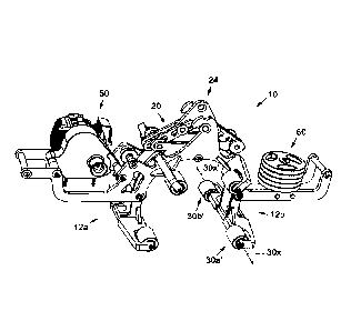
Selon un aspect, il est décrit un dispositif de rotation et un appareil de levage dun tuyau destinés à supporter et tourner un élément cylindrique ayant un axe longitudinal. Le dispositif de rotation et lappareil de levage dun tuyau comprennent une paire de mâchoires pivotant autour dun élément de pivot pour permettre au dispositif de rotation et à lappareil de levage dun tuyau dactionner entre une configuration ouverte et une configuration fermée. Une pluralité de rouleaux sont montés sur les mâchoires, chacun pouvant tourner autour dun axe de roulement. Lorsque le dispositif de rotation et lappareil de levage dun tuyau sont dans la configuration fermée, lélément cylindrique peut être saisi de manière rotative par le dispositif de rotation et lappareil de levage dun tuyau, ce qui permet à lélément cylindrique de tourner autour de son axe longitudinal. Idéalement, la pluralité de rouleaux sont disposés sur les mâchoires de manière à se faire face essentiellement les uns aux autres. Plus idéalement, laxe de roulement de chacun des rouleaux est essentiellement parallèle à laxe longitudinal de lélément cylindrique.


Abrégé anglais

In one aspect there is provided a pipe spinner and lifter for supporting and rotating a cylindrical member having a longitudinal axis. The pipe spinner and lifter comprises a pair of jaws that pivot about a pivot member, to allow the pipe spinner and lifter to actuate between an open configuration and a closed configuration. A plurality of rollers are mounted on the jaws, each rotatable about a rolling axis. When the pipe spinner and lifter is in the closed configuration, the cylindrical member can be rotatably captured by the pipe spinner and lifter, allowing the cylindrical member to rotate about its longitudinal axis. Preferably, the plurality of rollers are arranged in a substantially mirrored arrangement on the jaws. More preferably, the rolling axis of each of the rollers is substantially parallel to the cylindrical member's longitudinal axis.

Revendications

Note : Les revendications sont présentées dans la langue officielle dans laquelle elles ont été soumises.


THE EMBODIMENTS OF THE INVENTION IN WHICH AN EXCLUSIVE
PROPERTY OR PRIVILEGE IS BEING CLAIMED ARE DEFINED AS FOLLOWS:
1. A pipe spinner and lifter for supporting and rotating a cylindrical member
having a longitudinal axis, the pipe spinner and lifter comprising:
a pair of jaws that pivot about a pivot member to allow the pipe spinner and
lifter
to actuate between an open configuration and a closed configuration; and
a plurality of rollers mounted on said pair of jaws, each of said plurality of
rollers
rotating about a respective rolling axis;
wherein the cylindrical member may be rotatably captured by the pipe spinner
and lifter, to allow said cylindrical member to rotate about said longitudinal
axis in a substantially horizontal orientation, when the pipe spinner and
lifter is in the closed configuration.
2. The pipe spinner and lifter of claim 1 wherein the plurality of rollers are
arranged in a substantially mirrored arrangement on said pair of jaws.
3. The pipe spinner and lifter of claim 1 wherein the respective rolling axis
of
each of said plurality of rollers is substantially parallel to the cylindrical
member's
longitudinal axis when said cylindrical member is rotatably captured by the
pipe spinner
and lifter.
4. The pipe spinner and lifter of claim 1 wherein the pair of jaws each have
an
end; and

wherein at least one pair of the plurality of rollers is mounted substantially
on the
ends of said pair of jaws.
5. The pipe spinner and lifter of claim 1 further comprising at least one
guide
member to create a tensile member guide path within the pipe spinner and
lifter.
6. The pipe spinner and lifter of claim 5 wherein, when a tensile member is
first
wrapped around the cylindrical member and is then directed substantially
towards the
pivot member, said at least one guide member subsequently directs said tensile
member to a first side of the pipe spinner and lifter; and
wherein said tensile member does not engage said plurality of rollers.
7. The pipe spinner and lifter of claim 6 further comprising a source of pull
at said
first side of the pipe spinner and lifter.
8. The pipe spinner and lifter of claim 7 further comprising a counterweight
at a
second side of the pipe spinner and lifter, said second side being
substantially opposite
to said first side.
9. The pipe spinner and lifter of claim 8 wherein, when said tensile member is
operationally connected to the source of pull, said tensile member will cause
the
cylindrical member to rotate about its longitudinal axis when the source of
pull is
actuated.
11

10. A pipe spinner and lifter for supporting and rotating a cylindrical member
having a longitudinal axis, the pipe spinner and lifter comprising:
a pair of jaws that pivot about a pivot member to allow the pipe spinner and
lifter
to actuate between an open configuration and a closed configuration; and
a plurality of rollers mounted on said pair of jaws, each of said plurality of
rollers
rotating about a respective rolling axis;
wherein the cylindrical member may be rotatably captured by the pipe spinner
and lifter, to allow said cylindrical member to rotate about said longitudinal
axis in a substantially horizontal orientation, when the pipe spinner and
lifter is in the closed configuration;
wherein the plurality of rollers are arranged in a substantially mirrored
arrangement on said pair of jaws; and
wherein the respective rolling axis of each of said plurality of rollers is
substantially parallel to the cylindrical member's longitudinal axis when
said cylindrical member is rotatably captured by the pipe spinner and lifter.
11. The pipe spinner and lifter of claim 10 further comprising at least one
guide
member to create a tensile member guide path within the pipe spinner and
lifter;
wherein, when a tensile member is first wrapped around the cylindrical member
and is then directed substantially towards the pivot member, said at least
one guide member subsequently directs said tensile member to a first side
of the pipe spinner and lifter; and
12

wherein said tensile member does not engage said plurality of rollers.
12. The pipe spinner and lifter of claim 11 further comprising:
a source of pull at said first side of the pipe spinner and lifter; and
a counterweight at a second side of the pipe spinner and lifter, said
second side being substantially opposite to said first side;
wherein, when said tensile member is operationally connected to the
source of pull, said tensile member will cause the cylindrical
member to rotate about its longitudinal axis when the source of pull
is actuated.
13
Date Recue/Date Received 2023-06-28

Description

Note : Les descriptions sont présentées dans la langue officielle dans laquelle elles ont été soumises.


"PIPE SPINNER AND LIFTER"
FIELD OF THE INVENTION
The field of the present invention relates generally to providing a pipe
spinner and, more particularly, to providing a pipe spinner and lifter for
supporting
and rotating pipe and other cylindrical members in a substantially
horizontally
oriented manner to facilitate both lifting and threading sections of pipe
together.
BACKGROUND OF THE INVENTION
In the piping and pipeline industry there is often a need to move or
manipulate sections of pipe, as well as to thread together (or unthread)
sections of
pipe; e.g. such as during installation of pipelines and piping systems.
Sections of pipe may be moved manually, by being gripped and lifted
by one or more workers. Slings, chains and hydraulic lifting booms may also be
used to lift pipe. A scissor action pipe lifter or pipe clamp is often
employed to
securely lift and move sections of pipe, wherein the section of pipe is
securely
gripped in a substantially horizontal manner (i.e. with the pipe's
longitudinal axis
being oriented substantially horizontal) until the pipe is laid down or
released.
Scissor action pipe clamps normally comprise pads or the like on their jaws
which,
when the clamp is actuated during a lift, apply a high static friction force
against the
pipe to keep it from slipping while being lifted. However, this also prevents
the
section of pipe from rotating about its longitudinal axis while it is engaged
by a
scissor-type pipe clamp.
CA 3010169 2018-07-05

In spinning or rotating a pipe about its longitudinal axis, to thread or
unthread a pipe section, the practice heretofore has been to first position
the pipe in
place (e.g. on the ground, or on pipe stands with roller heads) and then to
use a
strap wrench or chain wrench to manually turn the pipe. Therefore, any pipe
rotation (threading/unthreading) would be done after a section of pipe was
positioned or lifted to the desired location, and after any scissor-type pipe
clamp has
disengaged from the section of pipe. However, this two-step process is very
labour
intensive, may create dangerous or worker safety issues, and often adds
significantly to the costs associated with pipeline or piping installations.
An advantage therefore exists to reduce or eliminate the need for such
manual labour and/or for a pipe clamp or lifter to also facilitate pipe
rotation (about a
pipe's longitudinal axis) while still being gripped or engaged by such a pipe
clamp.
BRIEF DESCRIPTION OF THE DRAWINGS
Referring to the drawings, several aspects of the present invention are
illustrated by way of example, and not by way of limitation, in detail in the
figures,
wherein:
FIG. 1 is a front perspective view of one embodiment of the pipe
spinner and lifter according to the present invention;
FIG. 2 is a front view of the pipe spinner and lifter of the embodiment
of FIG. 1;
2
CA 3010169 2018-07-05

FIG. 3 is a rear view of the pipe spinner and lifter of the embodiment
of FIG. 1;
FIG. 4 is a top view of the pipe spinner and lifter of the embodiment of
FIG. 1;
FIG. 5 is a bottom view of the pipe spinner and lifter of the
embodiment of FIG. 1;
FIG. 6 is another front perspective view of the pipe spinner and lifter of
the embodiment of FIG. 1;
FIG. 7 is another front perspective view of the pipe spinner and lifter of
.. the embodiment of FIG. 1, showing a tensile member wound therethrough;
FIG. 8 is a front perspective view of the pipe spinner and lifter of the
embodiment of FIG. 1, with some components hidden, so as to more clearly show
the tensile member wound therethrough;
FIG. 9 is a perspective view of another embodiment of a pipe spinner
and lifter according to the present invention, shown in the open configuration
about
to be positioned over a pipe;
FIG. 10 is a perspective view of the pipe spinner and lifter of the
embodiment of FIG. 9, shown positioned on a pipe; and
FIG. 11 is a perspective view of the pipe spinner and lifter of the
embodiment of FIG. 9, shown positioned on a pipe in the close configuration.
3
CA 3010169 2018-07-05

DETAILED DESCRIPTION OF THE PREFERRED EMBODIMENTS
The following description is of preferred embodiments by way of
example only and without limitation to the combination of features necessary
for
carrying the invention into effect. Reference is to be had to the Figures in
which
identical reference numbers identify similar components. The drawing figures
are
not necessarily to scale and certain features are shown in schematic or
diagrammatic form in the interest of clarity and conciseness.
Figures 1-11 show various embodiments of the invention for
supporting and rotating pipe and other cylindrical members while in a
substantially
horizontally orientation. Figures 1-8 show a preferred embodiment the pipe
spinner
and lifter 10. Figures 9-11 show another embodiment of the pipe spinner and
lifter
10, similar to the embodiment of Figures 1-8, but without a counterweight.
Referring generally to the embodiments in FIGS. 1-11, a pipe spinner
and lifter 10 preferably comprises a pair of jaws 12a,12b that each pivot
about a
pivot point or pivot member 14, so as to configure the pipe spinner and lifter
10
between an open or a closed configuration. Pivot member 14 may be a bushing,
bearing, pin or other suitable member to allow jaws 12a, 12b to pivot
thereabout.
When in the open configuration, the pipe spinner and lifter 10 can be
positioned
around a pipe P or other tubular member (e.g. see FIG. 9). When in the closed
configuration, the pipe spinner and lifter 10 will securely clamp onto a pipe
P (e.g.
see FIG. 11).
4
-
CA 3010169 2018-07-05

A conventional scissor linkage 20 is provided between the pair of jaws
12a, 12b and a lifting point or lifting member 24. Lifting member 24 may be a
lifting
lug having an opening 24o to receive a hook H, strap S or the like from a
crane or
boom B mounted on a boom truck BT, so as to move and suspend the pipe spinner
and lifter 10 above a pipe P in a conventional manner (e.g. FIG. 9). Lifting
member
24 is operationally connected to the pair of jaws 12a, 12b, via scissor
linkage 20 in a
conventional manner, so as to cause the pair of jaws 12a, 12b to actuate or
move
into the open configuration when the lifting member 24 is moved closer to the
pivot
member 14 (e.g. when released from boom truck BT), and to cause the pair of
jaws
12a, 12b to actuate or move into the closed configuration when the lifting
member
24 is moved away from the pivot member 14 (e.g. when being lifted by boom
truck
BT); all in a similar manner as how a conventional scissor-type pipe clamp is
actuated.
A plurality of rollers 30 are provided to the pair of jaws 12a, 12b, with
preferably at least one roller 30 on each of said jaw 12a and 12b. More
preferably,
a plurality of rollers 30 are provided to each of said jaw 12a and 12b in a
pair-wise
fashion, with one of each of said paired rollers (e.g. 30a, 30a') positioned
substantially at the front end 10f of the pipe spinner and lifter 10, and the
other of
said paired rollers (e.g. 30b, 30b') positioned substantially at the rear end
10r of the
pipe spinner and lifter 10, with each of said paired rollers (e.g. 30a, 30b)
rotating
about a shared rolling axis (e.g. 30x). For example roller 30a may be provided
on
jaw 12a at the front end 10f, and roller 30b may be provided on jaw 12a at the
rear
end 10r, both rollers 30a, 30b rotating about shared axis 30x.
5
CA 3010169 2018-07-05

Preferably, a plurality of paired rollers (e.g. 30a/30b, 30a'/30b',
30a"/30b", and 30a"I30b") are provided on the pair of jaws 12a, 12b in a
substantially mirrored arrangement (with the arrangement of rollers 30 on jaw
12b
being a substantially mirror image of the arrangement of rollers on jaw 12a),
each
pair rotating about its own rolling axis (e.g. 30x, 30x', 30x", and 30x");
e.g. as
shown in FIGS. 1-8. More preferably, each of the paired rollers' rolling axis
(e.g.
30x, 30x', 30x", and 30x") will be substantially parallel to a pipe's
longitudinal axis
PA, when a pipe is held by the pipe spinner and lifter 10 in the closed
configuration.
Even more preferably, at least one pair of rollers is provided at
substantially the tips
or ends 12e,12e' of each of the jaws 12a, 12b, so as to more easily enable the
pipe
spinner and lifter 10 to securably and rotatably capture a pipe P or other
tubular
member when in the closed configuration (e.g. rollers 30a/30b and 30a'/30b' in
FIGS 1-8). Still even more preferably, the pipe spinner and lifter 10 will
only engage
or contact the pipe P via rollers 30, thereby ensuring that the pipe P is
rotatably
.. captured when in the closed configuration.
Rollers 30 are of suitable dimensions and configuration to allow any
pipe P or other tubular member that may be held by the pipe spinner and lifter
10,
when in the closed configuration, to substantially, freely rotate R about the
pipe's
longitudinal axis PA (e.g. see FIG. 10) with minimal force or torque being
applied to
the pipe P. As will now be apparent to those skilled in the art, the pipe
spinner and
lifter 10, by virtue of the plurality of rollers 30 on the jaws 12a, 12b can
rotatably,
securably hold a pipe P or other tubular member (when in the closed
configuration)
so as to allow the pipe P to rotate about its longitudinal axis PA while still
being
6
CA 3010169 2018-07-05

securely held and/or lifted thereby. Advantageously, a pipe P or other tubular
member may be lifted with the pipe spinner and lifter 10 (in a substantially
similar
manner that conventional scissor-type pipe clamps would lift a pipe) and,
unlike
prior-art pipe lifters, the pipe P can also be rotated about its longitudinal
axis while
lifted; thereby making any threading/unthreading of a section of pipe
significantly
easier and safer.
In a preferred embodiment, the pipe spinner and lifter 10 further
comprises one or more pulleys, pins or guide members 40 to direct any tensile
member T, such as a rope or chain, that may be wrapped around a pipe P
substantially towards the pivot 14, and thereafter substantially to one side
10s of the
pipe spinner and lifter 10 (e.g. see FIG. 8). As such, said one or more
pulleys, pins
or guide members 40 thereby create a tensile member guide path GP within the
pipe spinner and lifter 10. Preferably, a source of pull 50 is provided on the
pipe
spinner and lifter 10 at said side 10s to where the tensile member T is
directed (e.g.
see FIG. 8). The source of pull 50 may be a winch 51 mounted on side 10s and
having a winch drum 52 to receive the tensile member T therearound. More
preferably, and to assist in maintaining the pipe spinner and lifter 10 in a
desired
orientation when suspended above a pipe P by lifting member 24, a
counterweight
60 is provided at an opposite side 10s' to the side 10s where the winch 51 is
mounted.
7
CA 3010169 2018-07-05

Advantageously, during operations when the pipe spinner and lifter 10
is in the closed configuration and has securably and rotatably captured a pipe
P, a
tensile member T may be first wrapped around the pipe P (e.g. FIG. 9), through
the
pipe spinner and lifter 10 towards the pivot 14, and then towards the source
of pull
50. Advantageously, when tensile member T is operationally connected to the
source of pull 50 (e.g. by being wrapped around drum 52), and when a pulling
force
is imparted from said source of pull 50, the tensile member T will cause the
pipe P
to rotate R about its longitudinal axis PA and be further directed towards the
pivot
14 within the jaws 12a, 12b; thereby further facilitating the secured
capturing of pipe
P by lifter 10 while in the closed configuration.
Preferably, tensile member T is sufficiently long so that it will not pull
entirely off of pipe P, and/or through the pipe spinner and lifter 10, while a
pulling
force is being applied to it during rotation operations. Advantageously,
tensile
member T and source of pull 50 act to rotate pipe P about its longitudinal
axis PA,
thereby obviating the need to manually rotate pipe P (e.g. with a strap
wrench) to
thread or unthread it. Those skilled in the art will now appreciate that
tensile
member T may be wrapped around the pipe P in either a clockwise or counter-
clockwise manner (relative to its longitudinal axis PA), thereby causing pipe
P to
rotated in either a clockwise or counter-clockwise manner when a pulling force
is
imparted from the source of pull 50 the tensile member T wrapped around pipe
P.
Moreover, those skilled in the art will now also appreciate that the side 10s
of the
pipe spinner and lifter 10 having the source of pull 50 may also be positioned
on
8
CA 3010169 2018-07-05

either side of the pipe's longitudinal axis PA, thereby providing another way
to
adjust the direction that pipe P may be rotated R about its longitudinal axis
PA.
Therefore, it will now be appreciated by those skilled in the art that by
varying the positioning of the source of pull 50 (on one side or the other of
pipe's
longitudinal axis PA) and/or by varying how tensile member T may be wrapped
around pipe P (clockwise or counterclockwise), a desired pipe rotation R about
its
longitudinal axis PA may be achieved when a pulling force is imparted from the
source of pull 50 the tensile member T wrapped around pipe P.
Preferably, the tensile member guide path GP is located substantially
midway between the front and rear ends 10f, 10r. More preferably, the tensile
member guide path GP is located substantially midway between each of the
paired
rollers 30 (e.g. substantially midway between rollers 30a/3019, see FIG. 4).
Advantageously, any force applied to the tensile member T by the source of
pull 50
will be substantially evenly distributed to all of the rollers 30, rather than
to the
rollers on either one of the front end 10f or the rear end 10r.
Those of ordinary skill in the art will appreciate that various
modifications to the invention as described herein will be possible without
falling
outside the scope of the invention. In the claims, the word "comprising" is
used in
its inclusive sense and does not exclude other elements being present. The
indefinite article "a" before a claim feature does not exclude more than one
of the
features being present.
9
CA 3010169 2018-07-05

Dessin représentatif
Une figure unique qui représente un dessin illustrant l'invention.
États administratifs

2024-08-01 : Dans le cadre de la transition vers les Brevets de nouvelle génération (BNG), la base de données sur les brevets canadiens (BDBC) contient désormais un Historique d'événement plus détaillé, qui reproduit le Journal des événements de notre nouvelle solution interne.

Veuillez noter que les événements débutant par « Inactive : » se réfèrent à des événements qui ne sont plus utilisés dans notre nouvelle solution interne.

Pour une meilleure compréhension de l'état de la demande ou brevet qui figure sur cette page, la rubrique Mise en garde , et les descriptions de Brevet , Historique d'événement , Taxes périodiques et Historique des paiements devraient être consultées.

Historique d'événement

Description Date
Inactive : Lettre officielle 2024-03-28
Inactive : Octroit téléchargé 2023-10-11
Accordé par délivrance 2023-10-03
Lettre envoyée 2023-10-03
Inactive : Page couverture publiée 2023-10-02
Requête pour le changement d'adresse ou de mode de correspondance reçue 2023-08-25
Préoctroi 2023-08-25
Inactive : Taxe finale reçue 2023-08-25
Lettre envoyée 2023-07-31
Un avis d'acceptation est envoyé 2023-07-31
Inactive : Q2 réussi 2023-07-25
Inactive : Approuvée aux fins d'acceptation (AFA) 2023-07-25
Lettre envoyée 2023-07-21
Modification reçue - modification volontaire 2023-06-28
Requête d'examen reçue 2023-06-28
Avancement de l'examen demandé - PPH 2023-06-28
Avancement de l'examen jugé conforme - PPH 2023-06-28
Toutes les exigences pour l'examen - jugée conforme 2023-06-28
Exigences pour une requête d'examen - jugée conforme 2023-06-28
Représentant commun nommé 2020-11-07
Demande publiée (accessible au public) 2020-01-03
Inactive : Page couverture publiée 2020-01-02
Représentant commun nommé 2019-10-30
Inactive : Correspondance - Formalités 2019-10-02
Inactive : Certificat dépôt - Aucune RE (bilingue) 2018-07-10
Inactive : CIB attribuée 2018-07-09
Exigences de rétablissement - réputé conforme pour tous les motifs d'abandon 2018-07-09
Inactive : CIB en 1re position 2018-07-09
Inactive : CIB attribuée 2018-07-09
Demande reçue - nationale ordinaire 2018-07-05
Déclaration du statut de petite entité jugée conforme 2018-07-03

Historique d'abandonnement

Il n'y a pas d'historique d'abandonnement

Taxes périodiques

Le dernier paiement a été reçu le 2023-06-09

Avis : Si le paiement en totalité n'a pas été reçu au plus tard à la date indiquée, une taxe supplémentaire peut être imposée, soit une des taxes suivantes :

  • taxe de rétablissement ;
  • taxe pour paiement en souffrance ; ou
  • taxe additionnelle pour le renversement d'une péremption réputée.

Les taxes sur les brevets sont ajustées au 1er janvier de chaque année. Les montants ci-dessus sont les montants actuels s'ils sont reçus au plus tard le 31 décembre de l'année en cours.
Veuillez vous référer à la page web des taxes sur les brevets de l'OPIC pour voir tous les montants actuels des taxes.

Historique des taxes

Type de taxes Anniversaire Échéance Date payée
Taxe pour le dépôt - petite 2018-07-03
TM (demande, 2e anniv.) - petite 02 2020-07-03 2020-05-19
TM (demande, 3e anniv.) - petite 03 2021-07-05 2021-05-31
TM (demande, 4e anniv.) - petite 04 2022-07-04 2022-06-01
TM (demande, 5e anniv.) - petite 05 2023-07-04 2023-06-09
Requête d'examen - petite 2023-07-04 2023-06-28
Taxe finale - petite 2018-07-03 2023-08-25
TM (brevet, 6e anniv.) - petite 2024-07-03 2024-05-30
Titulaires au dossier

Les titulaires actuels et antérieures au dossier sont affichés en ordre alphabétique.

Titulaires actuels au dossier
PRECISION FIBERGLASS PIPING INC.
Titulaires antérieures au dossier
COLIN TWERDOCLEB
NATHAN RISTAU
Les propriétaires antérieurs qui ne figurent pas dans la liste des « Propriétaires au dossier » apparaîtront dans d'autres documents au dossier.
Documents

Pour visionner les fichiers sélectionnés, entrer le code reCAPTCHA :


Pour visualiser une image, cliquer sur un lien dans la colonne description du document. Pour télécharger l'image (les images), cliquer l'une ou plusieurs cases à cocher dans la première colonne et ensuite cliquer sur le bouton "Télécharger sélection en format PDF (archive Zip)" ou le bouton "Télécharger sélection (en un fichier PDF fusionné)".

Liste des documents de brevet publiés et non publiés sur la BDBC .

Si vous avez des difficultés à accéder au contenu, veuillez communiquer avec le Centre de services à la clientèle au 1-866-997-1936, ou envoyer un courriel au Centre de service à la clientèle de l'OPIC.


Description du
Document 
Date
(aaaa-mm-jj) 
Nombre de pages   Taille de l'image (Ko) 
Dessins 2023-06-27 7 244
Revendications 2023-06-27 4 164
Dessin représentatif 2023-09-26 1 17
Revendications 2019-10-01 4 97
Abrégé 2019-10-01 1 20
Description 2018-07-04 9 313
Dessins 2018-07-04 7 396
Dessin représentatif 2019-12-19 1 13
Courtoisie - Lettre du bureau 2024-03-27 2 190
Paiement de taxe périodique 2024-05-29 1 25
Certificat de dépôt 2018-07-09 1 214
Avis du commissaire - Demande jugée acceptable 2023-07-30 1 579
Courtoisie - Réception de la requête d'examen 2023-07-20 1 422
Paiement de taxe périodique 2023-06-08 1 25
Documents justificatifs PPH 2023-06-27 12 987
Requête ATDB (PPH) 2023-06-27 14 733
Taxe finale / Changement à la méthode de correspondance 2023-08-24 3 78
Certificat électronique d'octroi 2023-10-02 1 2 527
Lettre de courtoisie 2018-07-08 2 60
Correspondance reliée aux formalités 2019-10-01 7 149
Paiement de taxe périodique 2020-05-18 1 25
Paiement de taxe périodique 2021-05-30 1 25
Paiement de taxe périodique 2022-05-31 1 25