Sélection de la langue

Search

Sommaire du brevet 3011588 

Énoncé de désistement de responsabilité concernant l'information provenant de tiers

Une partie des informations de ce site Web a été fournie par des sources externes. Le gouvernement du Canada n'assume aucune responsabilité concernant la précision, l'actualité ou la fiabilité des informations fournies par les sources externes. Les utilisateurs qui désirent employer cette information devraient consulter directement la source des informations. Le contenu fourni par les sources externes n'est pas assujetti aux exigences sur les langues officielles, la protection des renseignements personnels et l'accessibilité.

Disponibilité de l'Abrégé et des Revendications

L'apparition de différences dans le texte et l'image des Revendications et de l'Abrégé dépend du moment auquel le document est publié. Les textes des Revendications et de l'Abrégé sont affichés :

  • lorsque la demande peut être examinée par le public;
  • lorsque le brevet est émis (délivrance).
(12) Demande de brevet: (11) CA 3011588
(54) Titre français: MECANISME DE DETECTEUR DE POSITION D'ACTIONNEUR
(54) Titre anglais: ACTUATOR POSITION SENSOR MECHANISM
Statut: Examen
Données bibliographiques
(51) Classification internationale des brevets (CIB):
  • G01D 05/02 (2006.01)
  • B64C 13/34 (2006.01)
  • F16H 25/20 (2006.01)
  • F16H 57/00 (2012.01)
  • G01D 05/04 (2006.01)
(72) Inventeurs :
  • SARDI, ADIL (France)
(73) Titulaires :
  • RATIER-FIGEAC SAS
(71) Demandeurs :
  • RATIER-FIGEAC SAS (France)
(74) Agent: NORTON ROSE FULBRIGHT CANADA LLP/S.E.N.C.R.L., S.R.L.
(74) Co-agent:
(45) Délivré:
(22) Date de dépôt: 2018-07-16
(41) Mise à la disponibilité du public: 2019-03-18
Requête d'examen: 2023-07-14
Licence disponible: S.O.
Cédé au domaine public: S.O.
(25) Langue des documents déposés: Anglais

Traité de coopération en matière de brevets (PCT): Non

(30) Données de priorité de la demande:
Numéro de la demande Pays / territoire Date
17306211.8 (Office Européen des Brevets (OEB)) 2017-09-18

Abrégés

Abrégé anglais


The system of the present disclosure replaces the reduction gearbox of a
conventional system with a screw shaft and nut system wherein the position of
the
nut feeds into a linear sensor that determines the stabilizer position based
on the
nut position. The screw shaft and nut system in the position sensor train is
reflective
of the screw shaft and nut system and the stabilizer movement end of the
assembly
whereby rotation of the shaft causes axial movement of the nut along the
shaft.

Revendications

Note : Les revendications sont présentées dans la langue officielle dans laquelle elles ont été soumises.


- 5 -
CLAIMS
1. An actuator position measurement assembly comprising a sensor rotary
member (60) arranged to engage and rotate with a rotary member of an actuator,
and a sensor linearly moveable element (50) mounted on the sensor rotary
member
(60) that moves axially with respect to the sensor rotary member, and a linear
sensor coupled to the linearly moveable element (5) to provide an output
indicative
of the axial position of the linearly moveable element (60).
2. The actuator position measurement assembly of claim 1, wherein the sensor
rotary member comprises a rotating sensor shaft (60) and the linearly moveable
element (60) comprises a sensor nut mounted on the shaft and arranged to move
axially relative to and along the shaft on rotation of the shaft.
3. The actuator position measurement assembly of claim 2, further comprising
a sensor gear wheel (100a) coupled to the sensor shaft (60) and arranged to
rotate
with rotation of an actuator screw shaft (10), in use.
4. An actuation system comprising:
an actuator assembly comprising an actuator screw shaft on which is
mounted an actuator nut, the actuator screw shaft arranged to be rotated in
response to an actuator control signal and wherein rotation of the actuator
screw
shaft causes a relative axial movement of the actuator nut along the shaft,
and an
actuator position measurement assembly of any of 'claims 1 to 3, wherein the
actuator screw shaft is coupled to the sensor rotary member to cause
corresponding rotation of the sensor rotary member.
5. The actuation system of claim 4, wherein the actuator assembly is coupled
to the actuator position measurement assembly via a gear mechanism.
6. The actuation system of claim 5, wherein the gear mechanism comprises an
actuator gear wheel rotatably coupled to the actuator screw shaft and a sensor
gear
wheel rotatably coupled to the sensor rotary member, the actuator gear wheel
and
the sensor gear wheel in intermeshing rotary engagement.

- 6 -
7. An actuation system as claimed in claim 5 or 6, further comprising a
component to be moved, the component to be moved coupled to the actuator nut.

Description

Note : Les descriptions sont présentées dans la langue officielle dans laquelle elles ont été soumises.
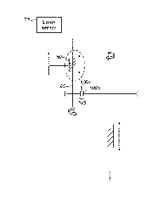

- 1 -
ACTUATOR POSITION SENSOR MECHANISM
TECHNICAL FIELD
The present disclosure relates to an actuator mechanism for moving a component
relative to a structure and sensing the component position for example, but
not
limited to, for moving a moveable part in an aircraft e.g. a flap or a
stabilizer. The
actuator mechanism of the disclosure finds application, for example, in a
trimmable
horizontal stabiliser actuator (THSA) but this is just one example.
BACKGROUND
Mechanical actuators find use in a very wide range of fields and applications
for
causing movement of a component in response to a control command through a
drive path. In the example of an actuator to control horizontal stabilizers at
an
aircraft tail, to adjust the longitudinal pitch or 'trim' of the aircraft,
conventionally a
so-called ball screw actuator is used. As described further below, with
reference to
Figure 1, such actuators are arranged to be driven by a drive means such as a
motor which causes a screw shaft to rotate. A nut mounted on the screw shaft
is
caused to move linearly relative to the shaft in response to rotation of the
shaft. The
nut is coupled to the stabilizer to move the stabilizer relative to the tail.
The
actuator needs to monitor the position of the stabilizer (i.e. monitor the
position of
the nut which is indicative of the position of the stabilizer. Conventionally,
this is
done by means of a position sensor assembly. The screw shaft is coupled, e.g.
via
a gear wheel, to a sensor wheel such that rotation of the shaft causes
rotation of
the sensor wheel. The sensor wheel rotates a sensor wheel shaft which is
coupled
to a stabilizer position sensor via a reduction gearbox (also sometimes called
a
mini-reducer).
A problem that has been identified with such convenLional actuator systems is
that
the position measuring cannot be performed directly on the output from the
actuator
assembly, and some movement conversion, e.g. by amplification or reduction
gear
mechanisms is required in the path from the actuator to the sensor. This
results in a
complex, bulky system that is difficult and expensive to manufacture, and that
can
suffer from inaccuracies in position sensing.
CA 3011588 2018-07-16

- 2 -
There is, therefore, a need for a smaller, simpler, more accurate position
sensor
train that avoids these problems.
SUMMARY
The system of the present disclosure replaces the reduction gearbox (a
multiple
stage gear train) with a screw shaft and nut system wherein the position of
the nut
feeds into a linear sensor that determines the stabilizer position based on
the nut
position. The screw shaft and nut system in the position sensor train is
reflective of
the screw shaft and nut system and the stabilizer movement end of the assembly
whereby rotation of the shaft causes axial movement of the nut along the
shaft.
Accordingly, there is provided an actuator position measurement assembly
comprising a sensor screw shaft arranged to engage and rotate with a screw
shaft
of an actuator, and a nut mounted on the sensor screw shaft that moves axially
with
respect to the sensor screw shaft, and a linear sensor coupled to the nut to
provide
an output indicative of the axial position of the nut.
The actuator position measurement assembly is preferably coupled as part of an
actuator assembly wherein the actuator comprises an actuator screw shaft on
which is mounted an actuator nut, the actuator screw shaft arranged to be
rotated in
response to an actuator control signal and wherein rotation of the actuator
screw
shaft causes a relative axial movement of the actuator nut along the shaft,
and
wherein the actuator screw shaft is coupled e.g. via a gear mechanism, to the
sensor screw shaft to cause corresponding rotation of the sensor screw shaft.
Preferably, the actuator nut is coupled to, e.g. via a link mechanism, a
component
to be moved by the actuator according to the actuator control signal.
BRIEF DESCRIPTION OF THE DRAWINGS
Figure 1 is a schematic diagram of a conventional position measurement system
for
an actuator assembly.
CA 3011588 2018-07-16

- 3 -
Figure 2 is a more detailed schematic diagram of the position sensor gear
train of a
system such as shown in Figure 1, with a detail of the coupling device.
Figure 3 is a schematic view of a modified assembly according to the present
disclosure.
DETAILED DESCRIPTION
Referring first to figures 1 and 2, conventional systems will first be
described. As
briefly described above, in a conventional system, th3 actuator mechanism
comprises an actuator screw shaft 10 that rotates in accordance with a
position
control signal e.g. from a motor or other control. In an aircraft, for
example, this
control signal could be generated automatically from flight controls, or
mechanically
by e.g. movement of a lever by a pilot. Rotation of the actuator screw shaft
10
causes axial movement of an actuator nut (not shown) mounted on the shaft. The
actuator nut is coupled to the component to be moved e.g. the horizontal
stabilizer,
so that the control command causes the shaft to rotate which causes the nut to
move axially which causes corresponding movement of the stabilizer or other
component to be moved.
It is necessary, for safe and reliable control, to measure or determine the
position of
the stabilizer during its movement. This is performed by the position sensor
assembly which determines the position of the actuator nut, and hence the
stabilizer, by monitoring the rotation of the actuator screw shaft 10. The
position
sensor assembly is coupled to the rotating actuator screw shaft e.g. via a
gear
mechanism comprising an actuator screw shaft gea: wheel 20 in intermeshing
engagement with a sensor wheel 4 of the sensor assembly. Rotation of the
actuator
screw shaft therefore causes rotation of the actuator screw shaft gear wheel
20
which in turn causes rotation of the sensor wheel 4. Rotation of the sensor
wheel 4
causes rotation of a sensor shaft 40 on which the sensor wheel is mounted.
The sensor shaft is therefore coupled to a reduction gear box 3 which, in
turn, is
connected to a position sensor 1 via a coupling device 2. A preferred coupling
device is sown in more detail in the dashed line extract of Figure 2. This
combined
reduction train of the reduction gear box and coupling device provides an
encoded
CA 3011588 2018-07-16

- 4 -
position indication to the position sensor from which the position sensor 1
can
determine the rotation of the actuator screw shaft and, hence, the actuator
nut and,
hence the component to be moved (not shown). Problems with such conventional
systems have been outlined above.
The system of the present disclosure replaces the reduction gearbox and
coupling
device and the rotary sensor with a linear sensor assembly that has a linearly
moveable component e.g. a sensor nut 50 mounted to and caused to move axially
with respect to a rotary component e.g. a sensor screw shaft 60 on which the
linearly moveable component is mounted. A linear sunsor detects the axial
position
of the linearly moveable component 50.
In an actuator system, the rotary component, shaft 60, engages with and
rotates in
response to rotation of the actuator screw shaft 10. As with conventional
systems,
the sensor shaft 60 may engage with the actuator screw shaft 10 via a gear
mechanism 100 similar to the wheels of the conventional system. Thus, rotation
of
the actuator shaft (which moves the actuator nut, which moves the stabilizer
or the
like) causes, via an actuator gear wheel 100b and a sensor gear wheel 100a, a
corresponding rotation of the sensor shaft 60 which causes a corresponding
axial
movement of the sensor nut 50 which is detected by the linear sensor 70.
The position sensing system provides a smaller, lighter, simpler and more
accurate
position measurement system that can be manufactured more easily and at lower
cost. The construction of the position sensor assembly also mirrors the
constructions of the actuator assembly.
The disclosure has been in relation to an example of a position measuring
assembly and actuator assembly used for e.g. controlling the position of a
horizontal stabilizer in an aircraft. The system described could, of course,
also be
used in other applications where a component is to be moved/positioned via an
actuator.
CA 3011588 2018-07-16

Dessin représentatif
Une figure unique qui représente un dessin illustrant l'invention.
États administratifs

2024-08-01 : Dans le cadre de la transition vers les Brevets de nouvelle génération (BNG), la base de données sur les brevets canadiens (BDBC) contient désormais un Historique d'événement plus détaillé, qui reproduit le Journal des événements de notre nouvelle solution interne.

Veuillez noter que les événements débutant par « Inactive : » se réfèrent à des événements qui ne sont plus utilisés dans notre nouvelle solution interne.

Pour une meilleure compréhension de l'état de la demande ou brevet qui figure sur cette page, la rubrique Mise en garde , et les descriptions de Brevet , Historique d'événement , Taxes périodiques et Historique des paiements devraient être consultées.

Historique d'événement

Description Date
Lettre envoyée 2023-07-31
Exigences pour une requête d'examen - jugée conforme 2023-07-14
Toutes les exigences pour l'examen - jugée conforme 2023-07-14
Requête d'examen reçue 2023-07-14
Représentant commun nommé 2020-11-07
Représentant commun nommé 2019-10-30
Demande publiée (accessible au public) 2019-03-18
Inactive : Page couverture publiée 2019-03-17
Inactive : CIB en 1re position 2018-09-30
Inactive : CIB attribuée 2018-09-30
Inactive : CIB attribuée 2018-09-18
Inactive : Certificat dépôt - Aucune RE (bilingue) 2018-07-23
Demande reçue - nationale ordinaire 2018-07-18

Historique d'abandonnement

Il n'y a pas d'historique d'abandonnement

Taxes périodiques

Le dernier paiement a été reçu le 2024-06-20

Avis : Si le paiement en totalité n'a pas été reçu au plus tard à la date indiquée, une taxe supplémentaire peut être imposée, soit une des taxes suivantes :

  • taxe de rétablissement ;
  • taxe pour paiement en souffrance ; ou
  • taxe additionnelle pour le renversement d'une péremption réputée.

Les taxes sur les brevets sont ajustées au 1er janvier de chaque année. Les montants ci-dessus sont les montants actuels s'ils sont reçus au plus tard le 31 décembre de l'année en cours.
Veuillez vous référer à la page web des taxes sur les brevets de l'OPIC pour voir tous les montants actuels des taxes.

Historique des taxes

Type de taxes Anniversaire Échéance Date payée
Taxe pour le dépôt - générale 2018-07-16
TM (demande, 2e anniv.) - générale 02 2020-07-16 2020-06-23
TM (demande, 3e anniv.) - générale 03 2021-07-16 2021-06-22
TM (demande, 4e anniv.) - générale 04 2022-07-18 2022-06-22
TM (demande, 5e anniv.) - générale 05 2023-07-17 2023-06-20
Requête d'examen - générale 2023-07-17 2023-07-14
TM (demande, 6e anniv.) - générale 06 2024-07-16 2024-06-20
Titulaires au dossier

Les titulaires actuels et antérieures au dossier sont affichés en ordre alphabétique.

Titulaires actuels au dossier
RATIER-FIGEAC SAS
Titulaires antérieures au dossier
ADIL SARDI
Les propriétaires antérieurs qui ne figurent pas dans la liste des « Propriétaires au dossier » apparaîtront dans d'autres documents au dossier.
Documents

Pour visionner les fichiers sélectionnés, entrer le code reCAPTCHA :


Pour visualiser une image, cliquer sur un lien dans la colonne description du document (Temporairement non-disponible). Pour télécharger l'image (les images), cliquer l'une ou plusieurs cases à cocher dans la première colonne et ensuite cliquer sur le bouton "Télécharger sélection en format PDF (archive Zip)" ou le bouton "Télécharger sélection (en un fichier PDF fusionné)".

Liste des documents de brevet publiés et non publiés sur la BDBC .

Si vous avez des difficultés à accéder au contenu, veuillez communiquer avec le Centre de services à la clientèle au 1-866-997-1936, ou envoyer un courriel au Centre de service à la clientèle de l'OPIC.

({010=Tous les documents, 020=Au moment du dépôt, 030=Au moment de la mise à la disponibilité du public, 040=À la délivrance, 050=Examen, 060=Correspondance reçue, 070=Divers, 080=Correspondance envoyée, 090=Paiement})


Description du
Document 
Date
(aaaa-mm-jj) 
Nombre de pages   Taille de l'image (Ko) 
Revendications 2018-07-15 2 44
Description 2018-07-15 4 161
Abrégé 2018-07-15 1 12
Dessins 2018-07-15 3 86
Dessin représentatif 2019-02-04 1 3
Paiement de taxe périodique 2024-06-19 48 1 989
Certificat de dépôt 2018-07-22 1 204
Courtoisie - Réception de la requête d'examen 2023-07-30 1 421
Requête d'examen 2023-07-13 5 173