Note : Les descriptions sont présentées dans la langue officielle dans laquelle elles ont été soumises.
CA 03015242 2018-08-17
1
Diecasting nozzle system
The present invention relates to a diecasting method and a diecasting nozzle
system
for use in a hot-chamber system for the diecasting of metal melt, comprising a
hot-
chamber diecasting machine with a casting vessel and a melt distributor, which
distributes the melt uniformly from a machine nozzle among uniformly heated
diecasting nozzles. Arranged between a sprue region of the diecasting nozzles
and the
casting vessel is at least one nonreturn valve, wherein the nonreturn valve
prevents the
melt from flowing back from the sprue region in the direction of the casting
vessel.
Sprue as a casting byproduct, which in conventional diecasting methods
solidifies In
the runners between the diecasting nozzle and the casting mold and connects
the
castings in an ultimately undesired manner after demolding, incurs additional
material
effort that generally accounts for 40 % to 100 % of the weight of the casting.
Even if the
sprue is remelted for material recycling, this involves energy and quality
losses due to
the creation of scum and oxide fractions. Sprueless diecasting avoids these
drawbacks.
For sprueless diecasting, it is necessary to either pass the melt in the
liquid state from
the melting pot to the mold and back for each casting, which however also
results in
losses in quality or at least in time losses, or to provision the melt in the
liquid state at
the sprue of the mold. The latter is done in the hot-chamber approach, where
all
runners are heated up to the sprue such that the melt remains liquid and,
favorably, is
at the same time prevented from flowing back to the melting pot.
The backflow to the melting pot can be prevented through valves, .but
particularly
advantageously also through a plug of solidified melt that closes the sprue
opening in
the diecasting nozzle.
While conventional valves do prevent backflow of the melt to the melting pot,
in the
case of multi-path systems they are ill-suited for preventing melt from
flowing from
upper-level paths into lower-level paths and from escaping from the diecasting
nozzle.
While this is prevented through closure using a plug of solidified melt, due
to the
required rapid alternations between melting and solidifying, it is complicated
to achieve
short work cycle times and thus high dynamics with this method.
CA 03015242 2018-08-17
2
This problem results in the object to provide a diecasting nozzle system for
use in a
diecasting hot-chamber system for metal melts which enables simple temperature
control and a simple structure.
The object is solved by a diecasting nozzle system for use in a hot-chamber
system for
the diecasting of metal melt, comprising a hot-chamber diecasting machine with
a
casting vessel and a melt distributor, which distributes the melt uniformly
from a
machine nozzle among heated diecasting nozzles, wherein at least one nonreturn
valve is arranged between a sprue region of the diecasting nozzles and the
casting
vessel, said nonreturn valve preventing the melt from flowing back from the
sprue
region in the direction of the casting vessel. For this, low-viscosity melts,
in particular of
non-ferrous metals, with a melting temperature up to that of aluminum are
predominantly provided. In the prior art, however, the liquid melt may be
retracted from
an upper nozzle and at the same time flow out of a lower nozzle in an
undesired
manner due to gravity.
To solve this problem, according to the invention, the nonreturn valve is
respectively
arranged between the sprue region of at least the upper diecasting nozzle, or
in the
case of multiple nozzles, the upper diecasting nozzles and a final branch in
the melt
distributor to each of the diecasting nozzles. Through this, melt can be
prevented from
escaping from the diecasting nozzles at any time when no melt is injected via
the melt
distributor, which would lead to contamination and hazards in particular in
the case of
an open mold. The risk of melt escape results from the fact that the melt
runners form
pipes communicating in the melt distributor, so that melt from a diecasting
nozzle
.. arranged in the upper region of the melt distributor may flow back and
accordingly melt
may flow out of a diecasting nozzle arranged in the lower region of the melt
distributor
due to the effect of gravity. This is however prevented by the nonreturn valve
in the
region between the sprue region of the diecasting nozzle and the final branch
in the
melt distributor to at least said diecasting nozzle, for example in the upper
diecasting
nozzle itself.
According to an advantageous embodiment, the diecasting nozzles can be heated
from
inside and/or from outside in the region of a nozzle body and comprise sprue
regions
that have at least a thermal conductivity of the melt to be processed and/or
can be
heated separately. It is particularly advantageous if the heating is performed
from
outside and the heat is transferred into the sprue regions, so that an
internal heater can
CA 03015242 2018-08-17
3
be dispensed with. Provision is thus made for the diecasting nozzle to be
heated from
outside, wherein the external heater may also be configured as a printed
heater (thick
film heater). The external heater may be formed through a brass or high-grade
steel
sleeve that can be shrink-fitted and contains the heater.
Due to the low heat dissipation from the sprue region, the diecasting nozzle
can thus
be heated indirectly by the heat transferred from the heated nozzle body into
the sprue
region. A heat conductivity as high as possible, and in any case not lower
than that of
the melt itself (e.g. Zn > 100 W/mK, Mg about > 60, Al about 235 W/mK), is
made
possible through appropriate material selection, for example a molybdenum
alloy,
tungsten or a heat conducting ceramic material. Alternatively or additionally,
the
diecasting nozzle is heated internally, which is also within the scope of the
invention.
It is further advantageous to provide a thermal protective device in the sprue
region of
each diecasting nozzle, which reduces heat dissipation from the sprue region
in the
direction of the casting mold. A thermal insulator located in the sprue region
is
particularly suitable for this. A thermal insulator may be envisaged here that
is
configured as an insulation ferrule made of a material surrounding the sprue
region and
having a low heat conductivity, such as titanium alloys or ceramics, or as an
insulating
air, gas or vacuum layer inside the sprue region, and/or as a constant air
layer between
the body of the diecasting nozzle and the casting mold, which forms a uniform
or
circumferential air gap acting as an insulating space. The insulation serves
to avoid
heat losses and to minimize the heating power.
The sprue region of the mold preferably includes an insulator which reduces
heat
dissipation into the mold. The insulator forms part of the nozzle and, in
contrast to
plastic injection moulding techniques, is not formed by the mold or the melt.
As an
alternative or in addition to said heat insulation, provision is further made
for the sprue
region of the mold to be heated, which creates an "active insulation" so to
speak, so as
to further reduce the heat dissipation from the sprue region by these
additional
measures. Through this, the melt in the sprue region remains in the liquid
state and
does not need to be melted again after separation of the casting. This
achieves a
heating of the nozzle in a simple manner while providing all the advantages of
provisioning the melt in the nozzle. To this end, provision is also made for
the front part
of the nozzle to be manufactured of an insulating material.
CA 03015242 2018-08-14
4
Alternatively, a further embodiment including a counter-heater is provided in
order to
reduce heat dissipation. Said counter-heater is preferably configured as a
segment that
is arranged around the sprue and can be temperature-controlled separately,
and/or as
a separately heatable sprue region. A counter-heater that uses a highly
dynamic CO2
cycle for its operation has proven to be particularly advantageous.
A high product quality is achieved by a melt runner which in the region of the
sprue
region of the diecasting nozzle includes a separation edge that is designed
such that it
forms a breaking point reducing a cross-section in the melt solidified in the
sprue
region, where the article will separate when the sprue region is lifted off
the mold. The
separation edge is arranged on one side either circumferentially on the outer
side of a
central duct or on the inner side of the melt duct, and in each case at the
lower end
located towards the sprue region. An arrangement on both sides may also be
provided.
Further, it has shown to be beneficial to arrange a temperature sensor in the
sprue
region. Said temperature sensor generates measured values that can be used to
control the nozzle heater. A controlled nozzle heater enables an optimized
procedure,
increases productivity and product quality, and reduces wear of the diecasting
nozzle.
The temperature sensor in the front region of the nozzle, which is the region
near the
sprue, thus assists in achieving an optimized operation of the heater in that
its
measured values are used to control the nozzle heater.
Arrangement of the nonreturn valve directly in the nozzle channel of the
diecasting
nozzle has shown to be particularly advantageous. A suitable nonreturn valve
includes
a freely moving ball, particularly in a cage, which cooperates with a valve
seat.
It is favorable if the nozzle includes a defined sprue geometry. A ring, for
example,
provides for a clean separation, and further provided shapes may be cross or
star
shapes. The central duct forming the ring may have a longitudinal hole
reaching
.. through the sprue region. This achieves an improved flow of the melt with
equally good
separation. The quality of the separation is further improved by a separation
edge that
may be arranged inside and/or outside in the sprue region. The diecasting
nozzle thus
advantageously has a sprue geometry that is adapted to the respective
requirements.
The sprue will cool down only if the heat flows into the casting, i.e. the
product, and
cools the sprue region as long as the casting remains connected to the sprue
region,
5
However, the sprue region does not cool down too far since, due to a thermal
insulation in the
sprue region of the nozzle, only a small amount of heat dissipates directly
into the mold. This
way, the heat flow is essentially canalized via the liquid or solidified melt.
A further aspect of the invention is a diecasting method that uses a
diecasting nozzle system
according to the above description. The diecasting method comprises the
following method
steps:
= fitting the permanently and uniformly heated diecasting nozzle onto the
casting mold;
= opening the nonreturn valve during injection of the melt through the melt
runner and the
sprue region into the casting mold;
= solidifying the melt to obtain a product inside the casting mold
including the sprue region,
wherein heat flows from the sprue region into the product;
= lifting off the diecasting nozzle, separating the product, and non-
occurrence of heat
dissipation from the sprue region;
= melting the solidified melt in the sprue region of each of the diecasting
nozzles through
continued heat flow from the nozzle body, wherein melt flowing from the upper
nozzles
via the distributor is prevented from flowing out of the lower nozzles in the
distributor by
closing the nonreturn valves in the region of the upper nozzles.
Such a method does not require formation of a sealing melt plug in the sprue
region, so that
the diecasting work cycle frequency can be increased and the alternating
thermal stress on
the diecasting nozzle can be reduced. Also, melt can be prevented more
reliably from
escaping.
SUMMARY OF THE INVENTION
According to an aspect of the invention, there is provided a diecasting nozzle
system for use
in a hot-chamber system for the diecasting of metal melt, comprising a hot-
chamber
diecasting machine with a casting vessel and a melt distributor, which
distributes the melt
uniformly from a machine nozzle among heated diecasting nozzles, wherein at
least one
nonreturn valve is arranged between a sprue region of the diecasting nozzles
and the casting
vessel, wherein said nonreturn valve prevents the melt from flowing back from
the sprue
region in the direction of the casting vessel, characterized in that the
nonreturn valve is
respectively arranged between the sprue region of at least the one upper
diecasting nozzle or
Date Recue/Date Received 2021-09-16
5a
all the upper diecasting nozzles and a final branch of melt runners in the
melt distributor to
each of the respective diecasting nozzles, wherein the nonreturn valve is
arranged in a nozzle
channel of the diecasting nozzle, wherein a thermal protective device, which
reduces heat
dissipation from the sprue region in the direction of the casting mold, is
provided in the sprue
region of each diecasting nozzle.
According to another aspect of the invention, there is provided a diecasting
method, which
uses a diecasting nozzle system as described above, characterized by the
following method
steps:
= fitting the heated diecasting nozzles onto the casting mold;
= opening the nonreturn valve during injection of the melt through the melt
runner and
the sprue region into the casting mold;
= solidifying the melt to obtain a product inside the casting mold
including the sprue
region, wherein heat flows from the sprue region into the product;
= lifting off the diecasting nozzles, separating the product, and non-
occurrence of heat
dissipation from the sprue region;
= melting the solidified melt in the sprue region of each of the diecasting
nozzles through
continued heat flow from the diecasting nozzles, wherein melt flowing from the
upper
diecasting nozzles via the melt distributor is prevented from flowing out of
the lower diecasting
nozzles in the melt distributor by closing the nonreturn valves in the region
of the upper
diecasting nozzles.
Further details, features and advantages of the invention become apparent from
the following
description of embodiment examples with reference to the associated drawings.
In the
drawings:
Fig. 1 is a schematic illustration of a diecasting nozzle system according to
the invention;
Fig. 2 is a schematic cross-sectional illustration of a diecasting nozzle
system according to
the invention with two diecasting nozzles;
Fig. 3 shows a further embodiment of the diecasting nozzle;
Fig. 4 shows an embodiment of a detail of the diecasting nozzle according to
the invention in
the sprue region;
Date Recue/Date Received 2022-11-28
5b
Fig. 5 shows a further embodiment of the diecasting nozzle system according to
the invention;
Fig. 6 shows a further embodiment of the diecasting nozzle system according to
the invention;
Date Recue/Date Received 2022-11-28
6
Fig. 7 shows a further embodiment of the diecasting nozzle according to the
invention and
Fig. 8 shows a number of different sprue geometries.
Fig. 1 schematically illustrates a hot-chamber system 1 comprising an
embodiment of a
diecasting nozzle system 10 according to the invention connected to a
conventionally known
hot-chamber diecasting machine 2. The hot-chamber diecasting machine 2
comprises a
casting vessel 3, which contains melt 4. The latter is forced downward by a
piston 5, which is
driven by a piston drive 6, so that the melt 4 reaches the diecasting nozzle
system 10 via a
machine nozzle 7.
In the diecasting nozzle system 10, the melt 4 is first forced into the melt
distributor 20, which
distributes the melt 4 among the individual diecasting nozzles 40. The
diecasting nozzles 40
are directly connected to the static mold half 32 as a part of the casting
mold 30. Located
between the static mold half 32 and a moving mold half 34 is a cavity 36 in
which the product
36' is formed upon injection and solidification of the melt 4.
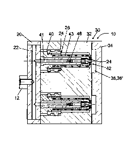
Fig. 2 is a schematic cross-sectional illustration of an embodiment of a
diecasting nozzle
system 10 according to the invention with two diecasting nozzles 40, an upper
one and a
lower one. The diecasting nozzles 40 are inserted into the static mold half 32
of the casting
mold 30 and are connected to the melt distributor 20. Two radial seats 24 and
an axial seat
26, at which the diecasting nozzle 40 is supported, secure it in its position
inside the casting
mold 30. The sealing function of the front radial seat 24 may further also be
improved by an
additional sealing member, which is not depicted here. The function of this
gap will be
described in more detail in connection with Fig. 3.
When the diecasting nozzle system 10 is in operation, the machine nozzle is
positioned at a
machine nozzle boss 12, via which it is fitted, and thus tightly connected, to
the melt
distributor 20 under mechanical pressure. Through this, the melt can flow from
the casting
vessel into a melt runner 22 of the melt distributor 20 and to the diecasting
nozzles 40 and
reach their respective nozzle channels 41. From the nozzle channel 41, the
melt flows
through the nonreturn valve 48, which opens in the flow direction, to the
sprue region 42,
where it is injected into the cavity 36. There, the product 36' is formed upon
solidification of
CA 3015242 2020-02-10
7
the melt in the cavity. The melt may further also solidify in the sprue region
42 since the heat
of the melt is dissipated via the casting mold 30 (which is oftentimes
additionally cooled).
In a particularly advantageous embodiment, the nonretum valve is configured as
a ball valve
such that the ball has a low weight and performs a short stroke, for example
one millimeter.
This property enables the diecasting nozzle to perform its function according
to the invention
in a highly dynamic manner.
For removal of the finished product 36, the moving mold half 34 is lifted off.
In this process,
the product 36' is separated from the sprue region 42 of the diecasting nozzle
40. The
separation of the product 36' and the removal of the moving mold half 34 at
the same time
eliminates the dissipation of heat into the casting mold 30. The heat
generated by a nozzle
heater 43 and transferred to the diecasting nozzle 40 thereupon heats the
sprue region 42 far
enough for the melt solidified in the sprue region 42 to remelt. The nozzle
heater 43 is in this
case configured as a sleeve, for example made of brass or high-grade steel,
which contains
the heater and is fitted onto the body of the diecasting nozzle 40.
As a result, the sprue region in the diecasting nozzles 40 is open for the
ejection of the melt
again. As long as only one diecasting nozzle 40 is present, the melt would be
prevented from
escaping by capillary forces or lack of pressure balance. However, as soon as
multiple
diecasting nozzles are present, in particular arranged in a stacked manner,
air may enter the
upper diecasting nozzle 40 through the sprue region 42. The entering air then
causes a
pressure balance in the melt runner 22 of the melt distributor 20, so that the
melt may flow
back from the upper diecasting nozzle 40 to the melt runner 22 and may escape
from the
lower diecasting nozzle 40 in an undesired manner, in particular in the case
of an open
casting mold 30. The same applies of course if the melt does not solidify in
the sprue region
but remains fluid.
To prevent the melt from flowing out, a nonreturn valve 48 is provided
according to the
invention which prevents the melt from flowing back to the melt runner 22 of
the melt
distributor 20. As a result, due to the lack of pressure balance, melt cannot
escape
CA 3015242 2020-02-10
CA 03015242 2018-08-17
8
from the lower diecasting nozzle 40. Through this, even the sprue region 42 of
the
respectively lower nozzles remains practically sealed even without additional
measures
for closure such as a solidified melt plug or a nozzle needle.
Fig. 3 is a schematic cross-sectional illustration of an embodiment of the
diecasting
nozzle 40 of the diecasting nozzle system 10 according to the invention
including a
detail view of the sprue region 42. The diecasting nozzle 40 is coupled to the
melt
distributor 20, so that its melt runner 22 is in communication with the nozzle
channel
41. Further, the nonreturn valve 48, which is schematically illustrated here,
is
advantageously arranged inside the nozzle channel 41. However, it might just
as well
be arranged at any position in the depicted section of the melt runner 22.
Further shown are the nozzle heater 43 and (only in the detail view) a part of
the static
mold half 32, against which rests the diecasting nozzle 40. To avoid heat
dissipation
from the diecasting nozzle 40 to the static mold half 32 via the resting
support in the
sprue region 42, i.e. the radial seat 24, a thermal insulator is provided. In
the depicted
example, said insulator consists in an air space 58, which surrounds a
substantial part
of the diecasting nozzle 40, and in particular in a sprue insulator 50. The
sprue
insulator 50 is arranged directly in the sprue region 42. It consists of a
hollow space
into which air, some other gas or an insulating material has been introduced.
Moreover,
provision is made for the sprue region to be fabricated of a different
material having a
reduced heat conductivity, for example a ceramic material. The sprue insulator
50 may
be formed by joining parts configured to define the hollow space via a form
lock or an
adhesive connection.
The sprue insulator 50 particularly effectively prevents a large portion of
the heat from
being dissipated via the radial seat 24. This enables heating of the sprue
region 42 and
melting of melt solidified there via the existing nozzle heater 43 without
requiring
arrangement of an additional heater in the sprue region 42. However, such an
alternative solution, in which a separate nozzle heater is provided for the
sprue region,
is also within the scope of the invention.
Dotted lines with arrows in the detail view further indicate the path of the
melt flow in
the final section of the nozzle channel 41 and to the sprue region 42. In the
depicted
embodiment example, the sprue region 42 has an annular sprue geometry. The
latter
is formed by the melt runner 41 near the sprue region 42 having a central duct
61 that
CA 03015242 2018-08-17
9
passes the melt to the outside and into a cylindrical gap, which results in
the annular
sprue geometry. Further advantageous sprue geometries are shown in Fig. B.
Fig. 4 is a schematic cross-sectional illustration of an embodiment of a
detail of the
diecasting nozzle 40 according to the invention in the sprue region 42. As in
Fig. 3, the
melt flow in the nozzle channel 41 is indicated here as well.
An important feature of the diecasting nozzle 40 according to the invention is
shown in
the sprue region 42. The latter comprises a separation edge 60, which may be
provided on one side or on both sides, i.e. on the inner side at the central
duct 61
and/or on the outer side in the lower section of the melt duct 41 as a
respective
circumferential protrusion. Shown is a two-sided configuration in the inner
and outer
region, wherein the separation edge 60 creates a reduced cross-section between
the
product, which consists of the solidified melt, and the "frozen" sprue region,
i.e, the
melt plug formed in said region. Said reduced cross-section forms a breaking
point at
which the product separates from the melt plug in the sprue region in a
defined manner
and thus provides for the creation of a proper sprue on the product that does
not
require postprocessing.
Fig. 5 is a schematic illustration of an embodiment of the diecasting nozzle
system 10
according to the invention including, similar to the illustration of Fig. 3, a
detail view of
the sprue region 42, which in addition to the static mold half 32 also shows
the moving
mold half 34 and the cavity 36.
There are, however, a number of differences compared to the embodiment example
of
Fig. 3. These relate to the environment of the sprue region 42 and the nozzle
heater
44. The latter is embedded in a circumferential groove in the body of the
diecasting
nozzle 40.
At the sprue region 42, a part of the static mold half 32 is depicted, which
is formed
such that an insulating air space 58 forms between said fixed mold half and
the
diecasting nozzle 40. Also arranged in this region is a temperature sensor 62,
which Is
connected via a lead 63. In the detail view, the channel for said lead may
also be used
for a supply line of the heater.
CA 03015242 2018-08-17
Fig. 6 shows a schematic cross-sectional illustration, including a detail
view, of an
embodiment of the diecasting nozzle system 10 according to the invention,
which
differs from those shown in figures 3 and 5 with respect to the type of
heating and the
design of the sprue region 42. To improve the thermal insulation from the
static mold
5 half 32, the sprue region 42 is provided with an insulating ferrule 59,
which is for
example made of a titanium alloy. Said insulation ferrule is arranged at the
sprue
region 42 and surrounds the latter in the region of the radial seat 24.
In the illustrated embodiment example, the diecasting nozzle 40 is heated via
a printed
10 nozzle heater 45, which is applied to the body of the diecasting nozzle
40 in a helical
configuration and is protected by a moving protective sleeve.
Fig. 7 is a schematic cross-sectional illustration of a further embodiment of
a diecasting
nozzle 40' according to the invention, which substantially differs from the
embodiments
described above. It includes a nozzle heater 46 configured as an internal
heating rod.
The nozzle heater 46 is surrounded by the nozzle channel 41, which thereby has
the
shape of a hollow cylinder. Through this, the heat can easily be guided
directly to the
sprue region 42 without requiring any particular thermal insulation measures
to
counteract the heat dissipation. This embodiment is particularly advantageous
for the
use of melts with a melting temperature of more than 600 C or for multi
gating, in
which melt is supplied from one diecasting nozzle to multiple cavities located
closely
adjacent to one another.
The hollow-cylindrical nozzle channel 41 has no nonreturn valve since the
latter needs
to be arranged in the melt runner of the melt distributor when employing such
a
diecasting nozzle 40'.
The nozzle channel 41 connects to the sprue region 42, which in the present
embodiment example has a dot-shaped configuration.
Further sprue shapes are illustrated in Fig. 8.
View a) shows a sprue geometry of a multi-path nozzle, which can be used to
fill a
multi-cavity mold. In this case, the melt is then injected not only into one
cavity but into
multiple cavities arranged closely adjacent to one another, so that multiple
parts can be
fabricated with one nozzle,
CA 03015242 2018-08-17
11
View b) shows a sprue geometry that results from a cross-section of figures 2
to 6 and
is formed as an annular sprue with a large cross-section for short casting
times. The tip
arranged inside the ring, i.e. the central duct 61 (cf. figures 3 and 4)
provides for heat
transfer from the heated nozzle body into the sprue region and to this end is
made of a
material having a particularly high heat conductivity, for example a suitable
alloy.
Through this, any melt that may have solidified in the sprue region upon
separation of
the product and thus elimination of the heat sink is quickly remelted, so that
a new
diecasting cycle for fabrication of a further product can be started. This can
be
.. additionally supported especially if the entire sprue region is made of
said material
having a particularly high heat conductivity.
In view c) the annular sprue is supplemented by a dot-shaped sprue arranged
centrally
inside the ring, so that an even larger volumetric flow rate can be achieved
for the melt.
A dot-shaped sprue without the additional annular sprue may also be provided.
Such a
variant already results from the diecasting nozzle 40 illustrated in Fig. 7.
Views d) to f) respectively show a sprue geometry that provides similar
stability in the
sprue region but offers a quicker injection of the melt into the cavity,
particularly if the
latter has a larger volume. This is achieved by grooves originating laterally
from the
annular sprue geometry so as to form a line, two crossed lines, or a star-
shaped sprue
geometry.
CA 03015242 2018-08-17
12
List of reference numerals
1 hot-chamber system
2 hot-chamber diecasting machine
3 casting vessel
4 melt
piston
6 piston drive
7 machine nozzle
diecasting nozzle system
12 machine nozzle boss
melt distributor
22 melt channel
24 radial seat
26 axial seat
casting mold
32 static mold half
34 moving mold half
36 cavity
36' product
40, 40' diecasting nozzle
41 nozzle channel
42 sprue region
43 nozzle heater (sleeve)
44 nozzle heater (circumferential groove)
45 nozzle heater (moving sleeve)
46 nozzle heater (internal heater)
48 nonreturn valve
50 sprue insulator
58 insulating space
59 insulating ferrule
60 separation edge
61 central duct
62 temperature sensor
63 lead