Note : Les descriptions sont présentées dans la langue officielle dans laquelle elles ont été soumises.
CA 03017979 2018-09-14
WO 2017/189161
PCT/US2017/025195
SET CONNECTOR SYSTEMS FOR VENTING A FLUID RESERVOIR
CROSS-REFERENCE TO RELATED APPLICATION(S)
[0001] This PCT
application claims the benefit of, and claims priority to: United
States Patent Application Serial Number 15/140,229, filed April 27, 2016; and
the content
of the application cited above is incorporated by reference herein.
TECHNICAL FIELD
[0002]
Embodiments of the subject matter described herein relate generally to fluid
infusion devices for delivering a medication fluid to the body of a user. More
particularly, embodiments of the subject matter relate to set connector
systems for venting
a gas from a fluid reservoir of a fluid infusion device.
BACKGROUND
[0003] Certain
diseases or conditions may be treated, according to modern medical
techniques, by delivering a medication or other substance to the body of a
user, either in a
continuous manner or at particular times or time intervals within an overall
time period.
For example, diabetes is commonly treated by delivering defined amounts of
insulin to
the user at appropriate times. Some common modes of providing insulin therapy
to a user
include delivery of insulin through manually operated syringes and insulin
pens. Other
modern systems employ programmable fluid infusion devices (e.g., insulin
pumps) to
deliver controlled amounts of insulin to a user.
[0004] A fluid
infusion device suitable for use as an insulin pump may be realized as
an external device or an implantable device, which is surgically implanted
into the body
of the user. External fluid infusion devices include devices designed for use
in a
generally stationary location (for example, in a hospital or clinic), and
devices configured
for ambulatory or portable use (to be carried by a user). External fluid
infusion devices
may establish a fluid flow path from a fluid reservoir to the patient via, for
example, a
suitable hollow tubing. In many instances, the fluid reservoir requires
filling by the
patient prior to use in the external fluid infusion device. During the filling
of the fluid
reservoir, gas, such as air, may inadvertently become trapped in the fluid
reservoir.
[0005]
Accordingly, it is desirable to provide set connector systems for venting a
gas,
such as air, from a fluid reservoir for use with a fluid infusion device.
Furthermore, other
desirable features and characteristics will become apparent from the
subsequent detailed
1
CA 03017979 2018-09-14
WO 2017/189161
PCT/US2017/025195
description and the appended claims, taken in conjunction with the
accompanying
drawings and the foregoing technical field and background.
BRIEF SUMMARY
[0006] The
object of the present invention is solved by the subject-matter of the
independent claims; further embodiments are incorporated in the dependent
claims.
[0007]
According to various embodiments, provided is a set connector system for
venting a gas from a fluid reservoir of a fluid infusion device. The set
connector system
includes a connector system having a first body section coupled to a second
body section.
The first body section defines a bore in communication with a chamber and a
counterbore
of the second body section to define a fluid flow path from the fluid
reservoir. The
chamber of the second body section is in fluid communication with a vent
subsystem
defined through the second body section. The vent subsystem terminates in an
outlet, and
the vent subsystem directs gas in the fluid flow path through the second body
section to
the outlet.
[0008] Also
provided according to various embodiments is a fluid infusion device.
The fluid infusion device comprises a housing that receives a fluid reservoir,
and a set
connector system for venting a gas from the fluid reservoir. The set connector
system
includes a connector system having a first body section coupled to a second
body section.
The first body section defines a bore. The second body section includes a
counterbore
that receives a portion of the fluid reservoir. The bore of the first body
section and the
counterbore of the second body section cooperate to define a fluid flow path
from the
fluid reservoir. The second body section includes a vent subsystem in
communication
with the fluid flow path that terminates in an outlet, and the vent subsystem
directs gas in
the fluid flow path to the outlet.
[0009] This
summary is provided to introduce a selection of concepts in a simplified
form that are further described below in the detailed description. This
summary is not
intended to identify key features or essential features of the claimed subject
matter, nor is
it intended to be used as an aid in determining the scope of the claimed
subject matter.
BRIEF DESCRIPTION OF THE DRAWINGS
[0010] A more
complete understanding of the subject matter may be derived by
referring to the detailed description and claims when considered in
conjunction with the
2
CA 03017979 2018-09-14
WO 2017/189161
PCT/US2017/025195
following figures, wherein like reference numbers refer to similar elements
throughout
the figures.
[0011] Fig. 1
is a simplified block diagram representation of an embodiment of a fluid
delivery system according to various embodiments;
[0012] Fig. 2
is a plan view of an exemplary embodiment of a fluid delivery system
that includes a fluid infusion device having an exemplary set connector system
for
venting a gas from a fluid reservoir according to the various teachings of the
present
disclosure;
[0013] Fig. 3
is a cross-sectional view of the fluid infusion device of Fig. 2, taken
along line 3-3 of Fig. 2;
[0014] Fig. 3A
is a cross-sectional view of the fluid infusion device of Fig. 2, taken
along line 3A-3A of Fig. 2;
[0015] Fig. 4
is a perspective view of a connector system of the set connector system
of Fig. 2 according to the various teachings of the present disclosure;
[0016] Fig. 5
is a detail cross-sectional view of the connector system of Fig. 4, taken
from detail 5 of the cross-sectional view of Fig. 2;
[0017] Fig. 6
is a cross-sectional view of the connector system of Fig. 4, taken along
line 6-6 of Fig. 4;
[0018] Fig. 7
is a plan view of an exemplary embodiment of a fluid delivery system
that includes a fluid infusion device having an exemplary set connector system
for
venting a gas from a fluid reservoir according to the various teachings of the
present
disclosure;
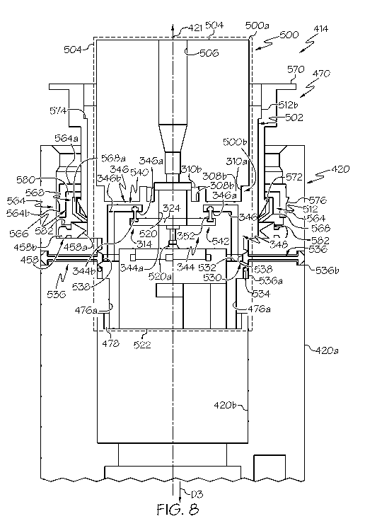
[0019] Fig. 8
is a is a cross-sectional view of the fluid infusion device of Fig. 7, taken
along line 8-8 of Fig. 7;
[0020] Fig. 9
is a perspective view of a connector system of the set connector system
of Fig. 7 according to the various teachings of the present disclosure;
[0021] Fig. 10
is a perspective view of the fluid infusion device or Fig. 7, in which a
portion of a housing of the fluid infusion device is illustrated in phantom;
and
[0022] Fig. 10A
is an exploded view of one or more rings and a sealing member
associated with a housing of the fluid infusion device of Fig. 7.
DETAILED DESCRIPTION
[0023] The
following detailed description is merely illustrative in nature and is not
intended to limit the embodiments of the subject matter or the application and
uses of
3
CA 03017979 2018-09-14
WO 2017/189161
PCT/US2017/025195
such embodiments. As used herein, the word "exemplary" means "serving as an
example, instance, or illustration." Any implementation described herein as
exemplary is
not necessarily to be construed as preferred or advantageous over other
implementations.
Furthermore, there is no intention to be bound by any expressed or implied
theory
presented in the preceding technical field, background, brief summary or the
following
detailed description.
[0024] Certain
terminology may be used in the following description for the purpose
of reference only, and thus are not intended to be limiting. For example,
terms such as
"top", "bottom", "upper", "lower", "above", and "below" could be used to refer
to
directions in the drawings to which reference is made. Terms such as "front",
"back",
"rear", "side", "outboard", and "inboard" could be used to describe the
orientation and/or
location of portions of the component within a consistent but arbitrary frame
of reference
which is made clear by reference to the text and the associated drawings
describing the
component under discussion. Such terminology may include the words
specifically
mentioned above, derivatives thereof, and words of similar import. Similarly,
the terms
"first", "second", and other such numerical terms referring to structures do
not imply a
sequence or order unless clearly indicated by the context.
[0025] As used
herein, the term module refers to any hardware, software, firmware,
electronic control component, processing logic, and/or processor device,
individually or
in any combination, including without limitation: application specific
integrated circuit
(ASIC), an electronic circuit, a processor (shared, dedicated, or group) and
memory that
executes one or more software or firmware programs, a combinational logic
circuit,
and/or other suitable components that provide the described functionality.
[0026]
Embodiments of the present disclosure may be described herein in terms of
functional and/or logical block components and various processing steps. It
should be
appreciated that such block components may be realized by any number of
hardware,
software, and/or firmware components configured to perform the specified
functions. For
example, an embodiment of the present disclosure may employ various integrated
circuit
components, e.g., memory elements, digital signal processing elements, logic
elements,
look-up tables, or the like, which may carry out a variety of functions under
the control of
one or more microprocessors or other control devices.
[0027] For the
sake of brevity, conventional techniques related to signal processing,
data transmission, signaling, control, and other functional aspects of the
systems (and the
individual operating components of the systems) may not be described in detail
herein.
4
CA 03017979 2018-09-14
WO 2017/189161
PCT/US2017/025195
Furthermore, the connecting lines shown in the various figures contained
herein are
intended to represent example functional relationships and/or physical
couplings between
the various elements. It should be noted that many alternative or additional
functional
relationships or physical connections may be present in an embodiment of the
present
disclosure.
[0028] The
following description relates to a fluid infusion device of the type used to
treat a medical condition of a user. The infusion device can be used for
infusing fluid into
the body of a user. The non-limiting examples described below relate to a
medical device
used to treat diabetes (more specifically, an insulin pump), although
embodiments of the
disclosed subject matter are not so limited. Accordingly, the infused
medication fluid is
insulin in certain embodiments. In alternative embodiments, however, many
other fluids
may be administered through infusion such as, but not limited to, disease
treatments,
drugs to treat pulmonary hypertension, iron chelation drugs, pain medications,
anti-cancer
treatments, medications, vitamins, hormones, or the like. For the sake of
brevity,
conventional features and characteristics related to infusion system
operation, insulin
pump and/or infusion set operation, fluid reservoirs, and fluid syringes may
not be
described in detail here. Examples of infusion pumps and/or related pump drive
systems
used to administer insulin and other medications may be of the type described
in, but not
limited to: U.S. Patent Publication Nos. 2009/0299290 and 2008/0269687; U.S.
Patent
Nos. 4,562,751; 4,678,408; 4,685,903; 5,080,653; 5,505,709; 5,097,122;
6,485,465;
6,554,798; 6,558,351; 6,659,980; 6,752,787; 6,817,990; 6,932,584; 7,621,893;
7,828,764;
and 7,905,868; which are each incorporated by reference herein.
[0029] Fig. 1
is a simplified block diagram representation of an embodiment of a fluid
delivery system 100, which can be utilized to administer a medication fluid
such as
insulin to a patient. The fluid delivery system 100 includes a fluid infusion
device 102
(e.g., an infusion pump) and a fluid conduit assembly 104 that is coupled to,
integrated
with, or otherwise associated with the fluid infusion device 102. The fluid
infusion device
102 includes a fluid reservoir 106 or an equivalent supply of the medication
fluid to be
administered. The fluid infusion device 102 is operated in a controlled manner
to deliver
the medication fluid to the user via the fluid conduit assembly 104. Although
not depicted
in Fig. 1, the fluid infusion device 102 also includes a set connector system
for venting
gas from the fluid reservoir 106.
[0030] The
fluid infusion device 102 may be provided in any desired configuration or
platform. In accordance with one non-limiting embodiment, the fluid infusion
device is
CA 03017979 2018-09-14
WO 2017/189161
PCT/US2017/025195
realized as a portable unit that can be carried or worn by the patient. In
this regard, Fig. 2
is a plan view of an exemplary embodiment of a fluid delivery system 200 that
includes a
portable fluid infusion device 202 and a fluid conduit assembly that takes the
form of an
infusion set component 204. The infusion set component 204 is coupled to the
fluid
infusion device 202. The fluid infusion device 202 accommodates a fluid
reservoir
(shown in Fig. 3) for the medication fluid to be delivered to the user.
[0031] The
illustrated embodiment of the infusion set component 204 includes,
without limitation: a tube 210; an infusion unit 212 coupled to the distal end
of the tube
210; and a set connector system 214 coupled to the proximal end of the tube
210. The
infusion set component 204 defines a fluid flow path that fluidly couples the
fluid
reservoir to the infusion unit 212. The fluid infusion device 202 is designed
to be carried
or worn by the patient, and the infusion set component 204 terminates at the
infusion unit
212 such that the fluid infusion device 202 can deliver fluid to the body of
the patient via
the tube 210. The fluid infusion device 202 may leverage a number of
conventional
features, components, elements, and characteristics of existing fluid infusion
devices. For
example, the fluid infusion device 202 may incorporate some of the features,
components,
elements, and/or characteristics described in United States Patent numbers
6,485,465 and
7,621,893, the relevant content of which is incorporated by reference herein.
[0032] In this
example, the fluid infusion device 202 includes a user interface 216 and
a display 218 coupled to a housing 220. The user interface 216 includes one or
more
input devices 222, which can be activated by the user. The user interface 216
can be used
to administer a bolus of insulin, to change therapy settings, to change user
preferences, to
select display features, and the like. Although not required, the illustrated
embodiment of
the fluid infusion device 202 includes the display 218. The display 218 can be
used to
present various types of information or data to the user, such as, without
limitation: the
current glucose level of the patient; the time; a graph or chart of the
patient's glucose
level versus time; device status indicators, etc. In some embodiments, the
display 218 is
realized as a touch screen display element and, therefore, the display 218
also serves as a
user interface component.
[0033] With
reference to Fig. 3, the housing 220 of the fluid infusion device 202
accommodates a power supply 224, a controller or control module 226, a drive
system
228 and a fluid reservoir system 230. In certain embodiments, the housing 220
also
includes a lock 232, which securely couples the fluid reservoir system 230 to
the housing
220 as will be discussed in greater detail herein. Generally, the power supply
224, the
6
CA 03017979 2018-09-14
WO 2017/189161
PCT/US2017/025195
control module 226 and the drive system 228 are accommodated in a pump chamber
220a
defined by the housing 220, and the fluid reservoir system 230 is accommodated
in a
reservoir chamber 220b defined by the housing 220. With reference to Fig. 3A,
the
housing 220 also includes a vent chamber 220c, which is defined adjacent to
the reservoir
chamber 220b. As will be discussed, the vent chamber 220c can be in fluid
communication with the set connector system 214 to receive fluid, such as air,
which is
vented from the set connector system 214. The vent chamber 220c is generally
fluidly
separated from or not in fluid communication with the pump chamber 220a. The
housing
220 can have any desired shape to accommodate the various components of the
fluid
infusion device 202, and thus, it will be understood that the shape and
configuration of
the housing 220 illustrated herein is merely exemplary.
[0034] With
reference back to Fig. 3, the power supply 224 is any suitable device for
supplying the fluid infusion device 202 with power, including, but not limited
to, a
battery. In one example, the power supply 224 can be removable relative to the
housing
220; however, the power supply 224 can also be fixed within the housing 220.
The
control module 226 is in communication with the user interface 216, display
218, power
supply 224 and drive system 228. The control module 226 controls the operation
of the
fluid infusion device 202 based on patient specific operating parameters. For
example,
the control module 226 controls the supply of power from the power supply 224
to the
drive system 228 to activate the drive system 124 to dispense fluid from the
fluid
reservoir system 230. Further detail regarding the control of the fluid
infusion device 202
can be found in U.S. Patent Nos. 6,485,465 and 7,621,893, the relevant content
of which
was previously incorporated herein by reference.
[0035] The
drive system 228 cooperates with the fluid reservoir system 230 to
dispense the fluid from the fluid reservoir system 230. In one example, the
drive system
228 includes a motor 234, a gear box 236, a drive screw 238 and a slide 240.
The motor
234 receives power from the power supply 224 as controlled by the control
module 226.
In one example, the motor 234 is an electric motor. The motor 234 includes an
output
shaft 234a. The output shaft 234a is coupled to the gear box 236. In one
embodiment,
the gear box 236 is a reduction gear box. The gear box 236 includes an output
shaft 236a,
which is coupled to the drive screw 238.
[0036] The
drive screw 238 includes a generally cylindrical distal portion 242 and a
generally cylindrical proximal portion 244. The distal portion 242 has a
diameter, which
can be larger than a diameter of the proximal portion 244. The distal portion
242 includes
7
CA 03017979 2018-09-14
WO 2017/189161
PCT/US2017/025195
a plurality of threads 242a. The plurality of threads 242a are generally
formed about an
exterior circumference of the distal portion 242. The proximal portion 244 is
generally
unthreaded, and can be sized to be received within a portion of the slide 240.
The
proximal portion 244 can serve to align the drive screw 238 within the slide
240 during
assembly, for example.
[0037] With
continued reference to Fig. 3, the slide 240 is substantially cylindrical
and includes a distal slide end 246, a proximal slide end 248 and a plurality
of threads
250. The distal slide end 246 is adjacent to the motor 234 when the slide 240
is in a first,
fully retracted position and the proximal slide end 248 is adjacent to the
drive screw 238
when the slide 240 is in the first, fully retracted position. The proximal
slide end 248
includes a projection 252 and a shoulder 254, which cooperate with the fluid
reservoir
system 230 to dispense the fluid from the fluid reservoir system 230. The
shoulder 254 is
defined adjacent to the projection 252 and contacts a portion of the fluid
reservoir system
230 to dispense fluid from the fluid reservoir system 230.
[0038] The
plurality of threads 250 of the slide 240 are formed along an interior
surface 240a of the slide 240 between the distal slide end 246 and the
proximal slide end
248. The plurality of threads 250 are formed so as to threadably engage the
threads 242a
of the drive screw 238. Thus, the rotation of the drive screw 238 causes the
linear
translation of the slide 240.
[0039] In this
regard, the slide 240 is generally sized such that in a first, retracted
position, the motor 234, the gear box 236 and the drive screw 238 are
substantially
surrounded by the slide 240. The slide 240 is movable to a second, fully
extended
position through the operation of the motor 234. The slide 240 is also movable
to a
plurality of positions between the first, retracted position and the second,
fully extended
position via the operation of the motor 234. Generally, the operation of the
motor 234
rotates the output shaft 234a, which is coupled to the gear box 236. The gear
box 236
reduces the speed and increases the torque output by the motor 234, and the
output shaft
236a of the gear box 236 rotates the drive screw 238, which moves along the
threads 250
formed within the slide 240. The movement or rotation of the drive screw 238
relative to
the slide 240 causes the movement or linear translation of the slide 240
within the
housing 220. The forward advancement of the slide 240 (i.e. the movement of
the slide
240 toward the fluid reservoir system 230) causes the fluid reservoir system
230 to
dispense fluid.
8
CA 03017979 2018-09-14
WO 2017/189161
PCT/US2017/025195
[0040] With
continued reference to Fig. 3, the fluid reservoir system 230 includes a
fluid reservoir 256 and a sealing member 258. The fluid reservoir 256 and the
sealing
member 258 are each received within an opening defined by the housing 220. The
sealing member 258 is coupled between the fluid reservoir 256 and the set
connector
system 214 to prevent the ingress of fluids into the reservoir chamber 220b of
the housing
220. In one example, the sealing member 258 comprises an 0-ring; however, any
suitable device can be used to prevent the ingress of fluids, as known to one
skilled in the
art.
[0041] With
reference to Fig. 3, the fluid reservoir 256 includes a body or barrel 260
and a stopper 262. The barrel 260 has a first or distal barrel end 264 and a
second or
proximal barrel end 266. Fluid 265 is retained within the barrel 260 between
the distal
barrel end 264 and the proximal barrel end 266. The distal barrel end 264 is
positioned
adjacent to the slide 240 when the fluid reservoir 256 is assembled in the
housing 220.
Generally, the distal barrel end 264 can have a substantially open perimeter
or can be
substantially circumferentially open such that the slide 240 is receivable
within the barrel
260 through the distal barrel end 264.
[0042] The
proximal barrel end 266 can have any desirable size and shape configured
to mate with at least a portion of the set connector system 214, as will be
discussed in
further detail herein. In one example, the proximal barrel end 266 defines a
passageway
266a through which the fluid 265 flows out of the fluid reservoir 256. The
passageway
266a is closed by a septum 268. The septum 268 is received within a portion of
the
proximal barrel end 266, and is coupled to the proximal barrel end 266 through
any
suitable technique, such as ultrasonic welding, press-fit, etc. The septum 268
serves as a
barrier to prevent the ingress of fluids into the fluid reservoir system 230,
and prevents
the egress of fluids from the fluid reservoir 256. The septum 268 is
pierceable by the set
connector system 214 to define a fluid flow path out of the fluid reservoir
256. In one
example, the set connector system 214 includes a connector system 270, a
hollow
instrument or needle 272 and the tube 210. As will be discussed, the connector
system
270 couples the needle 272 and the tube 210 to the fluid reservoir 256, and
includes a
vent subsystem 318 to vent trapped gas, such as air bubbles, which may be
contained
within the fluid reservoir 256, to the vent chamber 220c (Fig. 3A). The needle
272
defines a flow path for the fluid 265 out of the fluid reservoir 256, through
the connector
system 270 and into the tube 210.
9
CA 03017979 2018-09-14
WO 2017/189161
PCT/US2017/025195
[0043] In one
example, the housing 220 includes a retaining system 276, which
couples the set connector system 214 to the fluid reservoir 256. In one
example, the
retaining system 276 comprises one or more threads 276a and one or more
notches (not
shown). The one or more threads 276a threadably engage corresponding threads
278
(Fig. 4) defined in the connector system 270 to couple the connector system
270 to the
fluid reservoir 256.
[0044] With
reference to Fig. 3, the stopper 262 is disposed within the barrel 260.
The stopper 262 is movable within and relative to the barrel 260 to dispense
fluid from
the fluid reservoir 256. When the barrel 260 is full of fluid, the stopper 262
is adjacent to
the distal barrel end 264, and the stopper 262 is movable to a position
adjacent to the
proximal barrel end 266 to empty the fluid from the fluid reservoir 256. In
one example,
the stopper 262 is substantially cylindrical, and includes a distal stopper
end 277, a
proximal stopper end 279, at least one friction element 280 and a counterbore
282 defined
from the distal stopper end 277 to the proximal stopper end 279.
[0045] The
distal stopper end 277 is open about a perimeter of the distal stopper end
277, and thus, is generally circumferentially open. The proximal stopper end
279 is
closed about a perimeter of the proximal stopper end 279, and thus, is
generally
circumferentially closed. The proximal stopper end 279 includes a slightly
conical
external surface; however, the proximal stopper end 279 can be flat, convex,
etc. The at
least one friction element 280 is coupled to the stopper 262 about an exterior
surface of
the stopper 262. In one example, the at least one friction element 280
comprises two
friction elements, which include, but are not limited to, 0-rings. The
friction elements
280 are coupled to circumferential grooves defined in the exterior surface of
the stopper
262.
[0046] The
counterbore 282 receives the projection 252 of the slide 240 and the
movement of the slide 240 causes the shoulder 254 of the slide 240 to contact
and move
the stopper 262. In one example, the counterbore 282 includes threads;
however, the
projection 252 of the slide 240 is not threadably engaged with the stopper
262. Thus, the
threads illustrated herein are merely exemplary.
[0047] With
reference to Fig. 3, the set connector system 214 mates with and couples
to the proximal barrel end 266 of the fluid reservoir 256, establishing the
fluid path from
the fluid reservoir 256 to the tube 210. The set connector system 214 is
coupled to the
housing 220 of the fluid infusion device 202 and to the fluid reservoir 256 to
seal and
secure the fluid reservoir 256 inside the housing 220. Thereafter, actuation
of the fluid
CA 03017979 2018-09-14
WO 2017/189161
PCT/US2017/025195
infusion device 202 causes the medication fluid to be expelled from the fluid
reservoir
256, through the infusion set component 204, and into the body of the patient
via the
infusion unit 212 at the distal end of the tube 210. Accordingly, when the set
connector
system 214 is installed as depicted in Fig. 3, the tube 210 extends from the
fluid infusion
device 202 to the infusion unit 212 and the needle 272 provides a fluid
pathway to the
body of the patient. For the illustrated embodiment, the set connector system
214 is
realized as a removable reservoir cap (or fitting) that is suitably sized and
configured to
accommodate replacement of fluid reservoirs (which are typically disposable)
as needed.
[0048] With
reference to Fig. 4, the connector system 270 of the set connector system
214 is shown in greater detail. In Fig. 4, the connector system 270 is
illustrated without
the tube 210 for clarity. The connector system 270 is removably coupled to the
housing
220 and retains the fluid reservoir 256 within the housing 220. In this
example, the
connector system 270 includes a first body section 300 and a second body
section 302.
Each of the first body section 300 and the second body section 302 are
composed of a
polymeric material, such as a polycarbonate material, and the first body
section 300 and
the second body section 302 can each be formed through any suitable technique,
such as
injection molding, or 3D printing, for example. It should be noted that
although the first
body section 300 and the second body section 302 are illustrated as being
discrete
components, the first body section 300 and the second body section 302 can be
integrally
formed or one-piece (monolithic), if desired.
[0049] The
first body section 300 includes a graspable portion 304 and defines a bore
306. The graspable portion 304 enables the manipulation of the connector
system 270 by
a user, to remove or insert the connector system 270, and thus the fluid
reservoir 256,
from the housing 220. With reference to Fig. 5, Fig. 5 provides a detail view
of the cross-
section of Fig. 3, in which the fluid reservoir 256, the needle 272 and the
tube 210 are
removed for clarity. As shown in Fig. 5, the bore 306 extends from a first end
300a of the
first body section 300 to a second end 300b of the first body section 300. The
bore 306
receives the tube 210 and the needle 272, and generally, the tube 210 is
coupled adjacent
to the needle 272 within the bore 306 to define the fluid flow path out of the
connector
system 270. The second end 300b can also include one or more tabs 308. In this
example, the second end 300b defines two tabs 308a having a first width and
two tabs
308b having a second width. The first width is different than the second
width, and
generally, the second width is less than the first width. The tabs 308b can be
defined
adjacent to the bore 306, and the tabs 308a can be spaced radially outward
from the bore
11
CA 03017979 2018-09-14
WO 2017/189161
PCT/US2017/025195
306. The tabs 308a, 308b are each spaced apart from each other on the second
end 300b.
The two tabs 308a, 308b are received in corresponding channels 310a, 310b of
the second
body section 302. The tabs 308a, 308b can be fixedly coupled to the channels
310a,
310b, via ultrasonic welding, adhesives, etc.
[0050] The
second body section 302 is received within the housing 220, to retain the
fluid reservoir 256 (Fig. 3) within the housing 220. The second body section
302 has a
plane of symmetry 303. With reference back to Fig. 4, the second body section
302 is
generally annular, and includes a first end 312, a sidewall 314, a second end
316 and a
vent subsystem 318. The first end 312 defines the channels 310a, 310b, and
also includes
an annular chamber 320. The channels 310a, 310b and the annular chamber 320
may be
defined by common walls 312a, which extend outwardly from a surface of the
first end
312. With reference to Fig. 5, the annular chamber 320 extends from the first
end 312 to
a counterbore 322 of the second end 316. The annular chamber 320 is coaxial
with the
bore 306, and is coaxial with the counterbore 322 to receive the needle 272
therethrough
to define the fluid flow path from the fluid reservoir 256 to the tube 210
(Fig. 3).
Generally, the bore 306, the annular chamber 320 and the counterbore 322
extend along
an axis that defines a longitudinal axis 321 of the connector system 270.
[0051] In
various embodiments, the annular chamber 320 also receives a filter 324.
In one example, the needle 272 terminates adjacent to the filter 324, such
that the needle
272 and the tube 210 are on opposite sides of the filter 324 to ensure that
the fluid exiting
the fluid reservoir 256 flows through the filter 324 (Fig. 3). In one example,
a minimum
volume of the annular chamber 320 is about 0.7 microliters (mL). Generally,
the annular
chamber 320 has a height that enables the needle 272 to be received within the
annular
chamber 320 without piercing the filter 324. The annular chamber 320 can be
sterilized
prior to the insertion of the filter 324, and further, the annular chamber 320
can be plasma
treated to increase hydrophilicity, if desired.
[0052] The
filter 324 comprises a gas trapping filter, and is formed from a suitable
material, composition, or element such that the medication fluid can easily
pass through
the filter 324 during fluid delivery operations. The filter 324 can be formed
from a
hydrophilic, semi-hydrophilic, partially hydrophilic, or predominantly
hydrophilic
material. Although a truly hydrophilic material may be ideal, the material
used for the
filter 324 can be partially or predominantly hydrophilic while exhibiting some
amount of
hydrophobicity. In practice, the filter 324 can exhibit up to fifty percent
hydrophobicity
without adversely impacting the desired performance. For example, the filter
324 may
12
CA 03017979 2018-09-14
WO 2017/189161
PCT/US2017/025195
include or be fabricated from a hydrophilic membrane, a hydrophilic sponge
material, or
a hydrophilic foam material. As explained below, the filter 324 also serves to
filter
particulates from the medication fluid during fluid delivery operations.
Accordingly, the
filter 324 has a pore size that is small enough to inhibit the flow of
particulates. In certain
embodiments, the pore size is within the range of about 0.45 to 5.00 microns,
which is
suitable for most medical applications. Non-limiting examples of suitable
materials for
the filter 324 include: polyacrylate; polyurethane; nylon; cellulose acetate;
polyvinyl
alcohol; polyethelene foam; polyvinyl acetate; polyester fiber felt; polyester
(PET);
polysulfone; polyethyl sulfone; collagen; polycaprolactone; or the like. It
should be
appreciated that the material or materials used to fabricate the filter 324
can be treated to
enhance the hydrophilic characteristics if so desired.
[0053] One
function of the filter 324 is to inhibit the downstream flow of air bubbles.
Depending on the particular composition and configuration of the filter 324,
air bubbles
can be blocked by the filter 324 and/or retained within the filter 324 as the
liquid
medication flows downstream. Thus, the filter 324 may be realized as a gas
impermeable
membrane or material that also exhibits good hydrophilic properties.
Accordingly, no air
bubbles are present in the medication fluid that resides downstream from the
filter 324.
[0054] Another
benefit of the filter 324 relates to the volume accuracy of the fluid
delivery system. In certain implementations, syringe pumps are calibrated to
deliver a
specified volume in response to a controlled mechanical actuation (e.g.,
movement of the
syringe plunger in response to controlled rotation of an electric motor).
Reducing or
eliminating air from the fluid delivery path increases the accuracy of the
volume
calibrations.
[0055] In
certain embodiments, the filter 324 also serves to filter particulates from
the
medication fluid such that the particulate count of the downstream medication
fluid is
reduced. As mentioned above, the material used to fabricate the filter 324 can
be selected
with a desired pore size to accommodate filtering of particulates having an
expected size.
[0056] In some
embodiments, the filter 324 also serves to absorb and/or adsorb
certain substances, chemicals, or suspended elements from the medication
fluid. For
example, the filter 324 may include material that is configured or treated to
absorb/adsorb
lubricating or manufacturing oil that is associated with the manufacturing,
assembly, or
maintenance of one or more components of the fluid reservoir system 230. In
this regard,
a fluid reservoir for insulin can be fabricated with a trace amount of
silicone oil that
serves as a lubricant for the plunger of the fluid reservoir 256. Accordingly,
the filter 324
13
CA 03017979 2018-09-14
WO 2017/189161
PCT/US2017/025195
can include a material, layer, or treatment that reduces, traps, or otherwise
removes some
or all of the silicone oil from the medication fluid as it passes through the
filter 324.
[0057] In
certain embodiments, the filter 324 also serves as a drug depot during
operation of the fluid delivery system. To this end, the filter 324 can
include a drug,
medicine, chemical, or composition impregnated therein (or coated thereon, or
otherwise
carried by the filter 324). A quantity of the drug is released into the
medication fluid as
the fluid flows through the filter 324 during a fluid delivery operation. The
drug carried
by the filter 324 can be selected to address the needs of the particular
patient, fluid
delivery system, medication fluid, etc. In accordance with the exemplary
insulin infusion
system described here, the filter 324 is impregnated with a drug that treats
the patient site
to extend the useful life of the fluid infusion set. For example, the filter
324 can be treated
with an anticoagulant such as Heparin or Dextran. As another example, the
filter 324 can
be impregnated or infused with an anti-proliferative drug such as Rapamycin.
It should be
appreciated that these examples are neither exhaustive nor restrictive, and
that the filter
324 can be impregnated, treated, or infused with any drug that may be
appropriate and
suitable for the particular medical condition, fluid delivery system, or
application.
Generally, the gas trapped by the filter 324 (e.g. air bubbles) is vented from
the connector
system 270 to the vent chamber 220c (Fig. 3A) by the vent subsystem 318, as
will be
discussed further herein.
[0058] With
reference back to Fig. 4, the sidewall 314 extends about the perimeter or
circumference of the second body section 302. The sidewall 314 includes a pair
of arms
326, the threads 278 and a lock receptacle 328. The arms 326 are substantially
opposite
each other about the sidewall 314. The arms 326 are generally integrally
formed with the
sidewall 314, and include a living hinge that biases the arms 326 in a
direction away from
the sidewall 314. Stated another way, each of the arms 326 are defined so as
to be biased
radially outward from the second body section 302. The engagement of the
second body
section 302 with the housing 220 causes the compression of the arms 326, until
the arms
326 expand and engage a respective pocket (not shown) defined in the reservoir
chamber
220b of the housing 220. Thus, in this example, the arms 326 cooperate with
the lock 232
to secure the second body section 302 to the housing 220. Generally, the arms
326 also
provide tactile feedback that the connector system 270 is threaded fully into
the housing
220.
[0059] The
threads 278 are defined about a portion of the sidewall 314, so as to be
adjacent to the second end 316. In this example, the threads 278 comprise two
threads;
14
CA 03017979 2018-09-14
WO 2017/189161
PCT/US2017/025195
however, any number of threads can be employed to couple the connector system
270 to
the housing 220. In this example, each of the threads 278 defines an outlet
330. The
outlet 330 is in fluid communication with the vent subsystem 318 and is in
fluid
communication with the vent chamber 220c to vent the gas (e.g. air bubbles)
trapped by
the filter 324 to the vent chamber 220c (Fig. 3A). In one example, with
reference to Fig.
3A, each outlet 330 is in fluid communication with a respective bore 331
defined through
a wall 333 that separates the vent chamber 220c from the reservoir chamber
220b. With
reference back to Fig. 3, the outlet 330 includes a bore 332 and a seal 334.
The bore 332
is generally defined near a mid-point of the respective thread 278; however
the bore 332
can be defined through the respective thread 278 at any desired location. The
bore 332 is
generally circular; however, the bore 332 can have any desired shape. The seal
334
generally circumscribes the bore 332, and thus, the seal 334 is generally
annular. In one
example, the seal 334 comprises an 0-ring; however, the seal 334 can comprise
any
suitable sealing device. The seal 334 creates a seal between the second body
section 302
and the wall 333 dividing the vent chamber 220c and the reservoir chamber 220b
to
prevent the flow of fluids into the vent chamber 220c.
[0060] The lock
receptacle 328 receives a portion of the lock 232 to secure or lock the
connector system 270 to the housing 220. In one example, the lock receptacle
328 is
substantially rectangular; however, the lock receptacle 328 can have any
desired shape
that cooperates with the lock 232 to secure or lock the connector system 270
to the
housing 220.
[0061] With
reference to Fig. 5, the second end 316 defines the counterbore 322. In
certain embodiments, a second membrane can be disposed adjacent to or coupled
to the
second end 316 to enable air to vent from the reservoir chamber 220b, while
preventing
fluid from exiting the reservoir chamber 220b. In one example, the second
membrane
comprises a fluoropolymeric membrane. Generally, the second membrane has a
defined
breakthrough pressure, which allows only gas, such as air, to pass through the
second
membrane, and not liquids.
[0062] The vent
subsystem 318 is in fluid communication with the annular chamber
320 to transfer the gas captured by the filter 324 from the annular chamber
320 to the vent
chamber 220c of the housing 220. The vent subsystem 318 includes a first
conduit 340
and a second conduit 342, which each terminate at a respective outlet 330.
Generally, the
first conduit 340 is defined on a first side of the second body section 302,
and the second
conduit 342 is defined on an opposite side of the second body section 302,
such that the
CA 03017979 2018-09-14
WO 2017/189161
PCT/US2017/025195
trapped gas is directed from the annular chamber 320 in at least two different
directions to
enter the vent chamber 220c via a respective one of the outlets 330. Although
the vent
subsystem 318 is described and illustrated herein as comprising two conduits,
the first
conduit 340 and the second conduit 342, it will be understood that the vent
subsystem 318
can include any number of conduits.
[0063] Each of
the first conduit 340 and the second conduit 342 include a first conduit
passage 344, a second conduit passage 346, a third conduit passage 348 and a
fourth
conduit passage 350. Each of the first conduit passage 344, the second conduit
passage
346, the third conduit passage 348 and the fourth conduit passage 350 are in
fluid
communication to enable the transfer of gas, such as the trapped air, from the
annular
chamber 320 to the respective outlet 330. The first conduit passage 344 has a
first inlet
344a in fluid communication with the annular chamber 320, such that the filter
324 is
adjacent to the first inlet 344a. The first conduit passage 344 has a first
outlet 344b,
which is downstream from the first inlet 344a. The first conduit passage 344
extends
radially outward from the annular chamber 320, and extends along an axis that
is
substantially transverse, and in one example, substantially perpendicular to
the
longitudinal axis 321.
[0064] In this
example, a first valve 352 is coupled between the first outlet 344b, and
a second inlet 346a of the second conduit passage 346. The first valve 352
comprises a
suitable one-way valve, including, but not limited to, a poppet valve, a
duckbill valve, an
umbrella valve, and so on. The first valve 352 permits the flow of the trapped
gas from
the first outlet 344b to the second inlet 346a in a single direction only,
thereby preventing
or inhibiting a back flow into the first conduit passage 344.
[0065] The
second conduit passage 346 also includes a second outlet 346b, which is
downstream from the second inlet 346a. The
second outlet 346b is in fluid
communication with a third inlet 348a of the third conduit passage 348. The
second
conduit passage 346 extends radially outward from the annular chamber 320, and
extends
along an axis that is substantially transverse, and in one example,
substantially
perpendicular to the longitudinal axis 321. In this example, the second
conduit passage
346 is spaced apart from the first conduit passage 344, and is fluidly coupled
to the first
conduit passage 344 via the first valve 352.
[0066] The
third conduit passage 348 includes a third outlet 348b, which is in fluid
communication with a fourth inlet 350a of the fourth conduit passage 350. The
third
16
CA 03017979 2018-09-14
WO 2017/189161
PCT/US2017/025195
conduit passage 348 extends substantially along an axis that is substantially
parallel to the
longitudinal axis 321.
[0067] With
reference to Fig. 6, the fourth conduit passage 350 is shown in greater
detail. The fourth conduit passage 350 extends along an arc defined by the
sidewall 314.
The fourth conduit passage 350 includes a fourth outlet 350b, which is in
fluid
communication with the bore 332 of the respective outlet 330.
[0068] With
reference back to Fig. 2, the lock 232 securely couples the connector
system 270 to the housing 220. In one example, the lock 232 includes a locking
member
360 and a biasing member or spring 362. The locking member 360 is
substantially D-
shaped, and includes a base 364 and a curved lock arm 366. The locking member
360 is
slidably received within a first guide 368 and a second guide 370 defined
through a
portion of the housing 220. In this example, a respective portion of the
curved lock arm
366 is slidably received within a respective one of the first guide 368 and
the second
guide 370; however, it will be understood that other configurations are
possible.
[0069] The base
364 is curved, and generally follows a curvature of the housing 220,
although it will be understood that the base 364 can be flat or planar. With
reference to
Fig. 5, the base 364 defines an interior surface 364a, which is opposite an
exterior surface
364b. The interior surface 364a is coupled to the curved lock arm 366 and
defines a first
spring seat 374. The first spring seat 374 receives an end of the spring 362.
With
reference back to Fig. 2, the exterior surface 364b provides a contact surface
for a user to
touch to disengage the lock 232, and thereby release the connector system 270,
and the
fluid reservoir 256, from the housing 220.
[0070] The
curved lock arm 366 extends about a perimeter or circumference of the
second body section 302 of the connector system 270. In this example, with
reference to
Fig. 5, the curved lock arm 366 includes a tab 376, which is configured to
engage the lock
receptacle 328 of the second body section 302 to secure the connector system
270 to the
housing 220.
[0071] The
spring 362 biases the locking member 360 in a first, locked position, as
shown in Fig. 5. The spring 362 has a first end, which biases against the
first spring seat
374, and a second end, which biases against a second spring seat 378 defined
by a portion
of the housing 220. Generally, the spring 362 comprises a coil spring composed
of a
metal or metal alloy, but the spring 362 can comprise any suitable biasing
member. The
base 364 of the locking member 360 is movable in a direction D from the first,
locked
17
CA 03017979 2018-09-14
WO 2017/189161
PCT/US2017/025195
position to a second, release position, to compress the spring 362 and thereby
release the
connector system 270 from the housing 220.
[0072] With
reference to Fig. 3, with the housing 220 assembled with the power
supply 224, the control module 226 and the drive system 228, the fluid
reservoir system
230 can be coupled to the housing 220. In one example, a full fluid reservoir
256 is
inserted into the housing 220 such that the stopper 262 is adjacent to the
projection 252 of
the slide 240. The set connector system 214, with the needle 272 and the tube
210
coupled to the connector system 270, is then coupled to the housing 220. In
one example,
with reference to Fig. 5, the base 364 is moved in the direction D, to define
an opening
for receipt of the connector system 270. The connector system 270 is inserted
into the
housing 220 and rotated, by the first body section 300, for example, such that
the threads
278 engage the threads 276a of the housing 220. The connector system 270 is
rotated
until the arms 326 engage corresponding pockets defined in the reservoir
chamber 220b
to couple the connector system 270 to the housing 220. The base 364 of the
lock 232 is
released, and the spring 362 causes the tab 376 to engage the lock receptacle
328, thereby
fixedly coupling or securing the set connector system 214 to the housing 220.
[0073] With the
set connector system 214 fixedly coupled or secured to the housing
220, the needle 272 pierces the septum 268, thereby defining a fluid flow path
for the
fluid 265 out of the fluid reservoir 256. With the set connector system 214
coupled to the
fluid reservoir 256, one or more control signals from the control module 226
can drive the
motor 234, thereby rotating the drive screw 238, which results in the linear
translation of
the slide 240. The advancement of the slide 240 into the fluid reservoir 256
moves the
stopper 262, causing the fluid 265 to flow from the fluid reservoir 256
through the fluid
flow path defined by the set connector system 214.
[0074] As the
fluid flows through the needle 272, the fluid passes through the filter
324. Any gas (e.g. air bubbles) within the fluid is trapped by the filter 324.
As the
reservoir chamber 220b is generally operating under a pressure, which is
greater than a
pressure in the vent chamber 220c, the trapped gas is drawn through the filter
324 into the
first conduit 340 and the second conduit 342. The gas trapped by the filter
324 flows
from the filter 324 into the first inlet 344a of the first conduit passage 344
of each of the
first conduit 340 and the second conduit 342. The pressure of the gas in the
first conduit
passage 344 causes the first valve 352 to open, thereby exhausting the gas
from the first
conduit passage 344 into the second conduit passage 346. From the second
conduit
passage 346, the gas flows to the third conduit passage 348 and from the third
conduit
18
CA 03017979 2018-09-14
WO 2017/189161
PCT/US2017/025195
passage 348 the gas flows into the fourth conduit passage 350. The gas flows
from the
fourth conduit passage 350 and exits into the bore 332 of the respective
outlet 330, before
being exhausted into the vent chamber 220c (Fig. 3A).
[0075] In order
to remove the set connector system 214, for example, to replace an
empty fluid reservoir 256, with reference to Fig. 5, a force can be applied in
the direction
D to the base 364 to bias the lock 232 into the second, release position. With
the lock 232
in the second, release position, the first body section 300 can be rotated to
overcome the
force of the arms 326, and to uncouple the second body section 302 from the
threads
276a. The connector system 270 can then be removed from the housing 220, and
the
force can be removed from the base 364. With the force removed from the base
364, the
spring 362 returns the lock 232 to the first, locked position.
[0076] With
reference to Fig. 7, a plan view of an exemplary embodiment of a fluid
delivery system 400 that includes a portable fluid infusion device 402 and a
fluid conduit
assembly that takes the form of an infusion set component 404. The infusion
set
component 404 is coupled to the fluid infusion device 402. The fluid infusion
device 402
accommodates a fluid reservoir, such as the fluid reservoir 256 (Fig. 3), for
the
medication fluid to be delivered to the user. As the fluid infusion device 402
and the
infusion set component 404 are substantially similar to the fluid infusion
device 202 and
the infusion set component 204 discussed with regard to Figs. 1-6, only the
differences in
the fluid infusion device 402 and the fluid infusion device 202; and the
infusion set
component 404 and the infusion set component 204 will be discussed in great
detail
herein.
[0077] The
infusion set component 404 includes, without limitation: the tube 210; the
infusion unit 212 coupled to the distal end of the tube 210; and a set
connector system
414 coupled to the proximal end of the tube 210. The infusion set component
404 defines
a fluid flow path that fluidly couples the fluid reservoir to the infusion
unit 212. The fluid
infusion device 402 is designed to be carried or worn by the patient, and the
infusion set
component 404 terminates at the infusion unit 212 such that the fluid infusion
device 402
can deliver fluid to the body of the patient via the tube 210. The fluid
infusion device 402
may leverage a number of conventional features, components, elements, and
characteristics of existing fluid infusion devices. For example, the fluid
infusion device
402 may incorporate some of the features, components, elements, and/or
characteristics
described in United States Patent numbers 6,485,465 and 7,621,893, the
relevant content
of which is incorporated by reference herein.
19
CA 03017979 2018-09-14
WO 2017/189161
PCT/US2017/025195
[0078] The
fluid infusion device 402 includes the user interface 216 and the display
218 coupled to a housing 420. The user interface 216 includes the one or more
input
devices 222, which can be activated by the user. The housing 420 of the fluid
infusion
device 202 accommodates the power supply 224 (Fig. 3), the controller or
control module
226 (Fig. 3), the drive system 228 (Fig. 3) and a fluid reservoir system 430.
Generally,
the power supply 224, the control module 226 and the drive system 228 are
accommodated in the pump chamber 220a (Fig. 3) defined by the housing 420, and
the
fluid reservoir system 430 is accommodated in the reservoir chamber 220b (Fig.
8)
defined by the housing 420. The housing 420 can have any desired shape to
accommodate the various components of the fluid infusion device 402, and thus,
it will be
understood that the shape and configuration of the housing 420 illustrated
herein is
merely exemplary.
[0079] With
reference to Fig. 8, the fluid reservoir system 430 includes the fluid
reservoir 256 (Fig. 3) and a sealing member 458. The fluid reservoir 256 and
the sealing
member 458 are each received within an opening defined by the housing 420. The
sealing member 458 is coupled about a perimeter of a portion of the set
connector system
414 to prevent the ingress of fluids into the reservoir chamber 420b of the
housing 420.
In one example, the sealing member 458 comprises an 0-ring; however, any
suitable
device can be used to prevent the ingress of fluids, as known to one skilled
in the art. In
this example, the sealing member 458 includes a triangular end 458a and a
notched
trailing end 458b. The triangular end 458a contacts a connector system 470 of
the set
connector system 414. The notched trailing end 458b can contact one or more
rings 560
associated with the housing 420, as will be discussed in further detail below.
[0080] The set
connector system 414 includes a connector system 470, the needle 272
and the tube 210. As will be discussed, the connector system 470 couples the
needle 272
and the tube 210 to the fluid reservoir 256 (Fig. 3), and includes a vent
subsystem 518 to
vent trapped gas, for example, air bubbles, which may be contained within the
fluid
reservoir 256, to an ambient environment surrounding the housing 420. The
needle 272
defines a flow path for the fluid 265 out of the fluid reservoir 256, through
the connector
system 470 and into the tube 210.
[0081] In one
example, the housing 420 includes a retaining system 476, which
couples the set connector system 414 to the fluid reservoir 256 (Fig. 3). In
one example,
the retaining system 476 comprises one or more rails 476a. The one or more
rails 476a
are defined on opposing walls of the reservoir chamber 220b, and generally
extend along
CA 03017979 2018-09-14
WO 2017/189161
PCT/US2017/025195
an axis that is substantially parallel with a longitudinal axis 421 of the
housing 420, and
cooperate to receive corresponding grooves 478 defined in the connector system
470 to
assist in retaining the connector system 470 within the housing 420. In this
example, the
reservoir chamber 220b includes two rails 476a and the connector system 470
includes
two grooves 478, which are spaced apart about a perimeter or circumference of
the
connector system 470, however, the reservoir chamber 220b and the connector
system
470 can have any number of rails 476a and grooves 478, respectively.
Generally, each
groove 478 is defined about the connector system 470 so as to be substantially
opposite
the other groove 478.
[0082] With
reference to Fig. 7, the set connector system 414 mates with and couples
to the proximal barrel end 266 of the fluid reservoir 256 (Fig. 3),
establishing the fluid
path from the fluid reservoir 256 to the tube 210. The set connector system
414 is
coupled to the housing 420 of the fluid infusion device 202 and to the fluid
reservoir 256
(Fig. 3) to seal and secure the fluid reservoir 256 inside the housing 420.
Thereafter,
actuation of the fluid infusion device 402 causes the medication fluid to be
expelled from
the fluid reservoir 256, through the infusion set component 204, and into the
body of the
patient via the infusion unit 212 at the distal end of the tube 210.
Accordingly, when the
set connector system 414 is installed as depicted in Fig. 7, the tube 210
extends from the
fluid infusion device 202 to the infusion unit 212 and the needle 272 provides
a fluid
pathway to the body of the patient. For the illustrated embodiment, the set
connector
system 414 is realized as a removable reservoir cap (or fitting) that is
suitably sized and
configured to accommodate replacement of fluid reservoirs (which are typically
disposable) as needed.
[0083] With
reference to Fig. 8, the connector system 470 of the set connector system
414 is shown in greater detail. In Fig. 8, the connector system 470 is
illustrated without
the needle 272 and the tube 210 for clarity. The connector system 470 is
removably
coupled to the housing 420 and retains the fluid reservoir 256 within the
housing 420. In
this example, the connector system 470 includes a first body section 500 and a
second
body section 502. Each of the first body section 500 and the second body
section 502 are
composed of a polymeric material, such as a polycarbonate material, and the
first body
section 500 and the second body section 502 can each be formed through any
suitable
technique, such as injection molding, or 3D printing, for example. It should
be noted that
although the first body section 500 and the second body section 502 are
illustrated as
21
CA 03017979 2018-09-14
WO 2017/189161
PCT/US2017/025195
being discrete components, the first body section 500 and the second body
section 502
can be integrally formed or one-piece (monolithic), if desired.
[0084] The
first body section 500 includes a graspable portion 504 and defines a bore
506. The graspable portion 504 enables the manipulation of the connector
system 470 by
a user, to remove or insert the connector system 470, and thus the fluid
reservoir 256,
from the housing 420. The bore 506 extends from a first end 500a of the first
body
section 500 to a second end 500b of the first body section 500. The bore 506
receives the
tube 210 and the needle 272, and generally, the tube 210 is coupled adjacent
to the needle
272 within the bore 506 to define the fluid flow path out of the connector
system 470.
The second end 500b can also include the one or more tabs 308. In this
example, the
second end 500b defines the two tabs 308a having the first width and the two
tabs 308b
having the second width. The two tabs 308a, 308b are received in corresponding
channels 310a, 310b of the second body section 502. The tabs 308a, 308b can be
fixedly
coupled to the channels 310a, 310b, via ultrasonic welding, adhesives, etc.
[0085] The
second body section 502 is received within the housing 420, to retain the
fluid reservoir 256 (Fig. 3) within the housing 420. The second body section
502 has a
plane of symmetry 503. With reference to Fig. 9, the second body section 502
is
generally annular, and includes a first end 512, a sidewall 514, a second end
516 and a
vent subsystem 518 (Fig. 8). The first end 512 defines the channels 310a,
310b, and also
includes an annular chamber 520 (Fig. 8). The channels 310a, 310b and the
annular
chamber 520 may be surrounded by a flange 512a, which extends upwardly about
the
perimeter of the second body section 502 from a surface of the first end 512
to provide
additional strength to the first body section 500.
[0086] With
reference to Fig. 8, the annular chamber 520 extends from the first end
512 to an area adjacent to a counterbore 522 of the second end 516. In one
example, the
annular chamber 520 is coupled to the counterbore 522 via a passageway 520a,
which is
sized to receive the needle 272 (Fig. 3). The annular chamber 520 is coaxial
with the
bore 506, and is coaxial with the passageway 520a and the counterbore 522 to
receive the
needle 272 therethrough to define the fluid flow path from the fluid reservoir
256 to the
tube 210. Generally, the bore 506, the annular chamber 520, the passageway
520a and
the counterbore 522 extend along an axis that is substantially parallel with
the
longitudinal axis 421.
[0087] In
various embodiments, the annular chamber 520 also receives the filter 324.
In this example, the needle 272 terminates adjacent to the filter 324, such
that the needle
22
CA 03017979 2018-09-14
WO 2017/189161
PCT/US2017/025195
272 and the tube 210 are on opposite sides of the filter 324 to ensure that
the fluid exiting
the fluid reservoir 256 flows through the filter 324 (Fig. 3). In one example,
a minimum
volume of the annular chamber 520 is about 0.7 microliters (mL). Generally,
the annular
chamber 520 has a height that enables the needle 272 to be received within the
annular
chamber 520 without piercing the filter 324. The annular chamber 520 can be
sterilized
prior to the insertion of the filter 324, and further, the annular chamber 520
can be plasma
treated to increase hydrophilicity, if desired. Generally, the gas (e.g. air
bubbles) trapped
by the filter 324 is vented from the connector system 470 to the ambient
environment
external to the housing 220 by the vent subsystem 518, as will be discussed
further
herein.
[0088] With
reference back to Fig. 9, the sidewall 514 extends about the perimeter or
circumference of the second body section 502, and cooperates with the flange
512a to
define an exterior surface of the second body section 502. The sidewall 514
includes the
grooves 478 and one or more outlets 530. In this example, the outlets 530
comprise two
outlets 530, which are spaced apart from a respective one of the grooves 478.
The
grooves 478 are defined through the sidewall 514 from the second end 516 in a
direction
towards the first end 512.
[0089] Each
outlet 530 is in fluid communication with the vent subsystem 518 and is
in fluid communication with a respective conduit 536 defined through the
housing 420
(Fig. 8) to vent the air trapped by the filter 324 to an ambient environment
surrounding
the housing 420. Each outlet 530 includes a bore 532 and a seal 534. The bore
532 is
generally circular; however, the bore 532 can have any desired shape. The seal
534
generally circumscribes the bore 532, and thus, the seal 534 is generally
annular. In one
example, the seal 534 comprises an 0-ring; however, the seal 534 can comprise
any
suitable sealing device. The seal 534 creates a seal between the second body
section 302
and the reservoir chamber 420b to ensure that the trapped gas passes into the
conduit 536
(Fig. 8).
[0090] With
reference to Fig. 8, a membrane 538 substantially surrounds the outlets
530 and the conduit 536. The membrane 538 is positioned between each of the
outlets
530 and each of the conduits 536 to assist in removing gas trapped in the
reservoir
chamber 220b. In one example, the membrane 538 comprises a fluoropolymeric
membrane. Generally, the membrane 538 has a defined breakthrough pressure,
which
allows only gas, such as air, to pass through the membrane 538, and not
liquids. The
second end 516 defines the counterbore 522.
23
CA 03017979 2018-09-14
WO 2017/189161
PCT/US2017/025195
[0091] The vent
subsystem 518 is in fluid communication with the annular chamber
520 to transfer the gas captured by the filter 324 from the annular chamber
520 to the
conduits 536 of the housing 420. The vent subsystem 518 includes a first
conduit 540
and a second conduit 542, which each terminate at a respective outlet 530.
Generally, the
first conduit 540 is defined on a first side of the second body section 502,
and the second
conduit 542 is defined on an opposite side of the second body section 502,
such that the
trapped gas is directed from the annular chamber 520 in at least two different
directions to
enter the conduits 536 via a respective one of the outlets 530. Although the
vent
subsystem 518 is described and illustrated herein as comprising two conduits,
the first
conduit 540 and the second conduit 542, it will be understood that the vent
subsystem 518
can include any number of conduits.
[0092] Each of
the first conduit 540 and the second conduit 542 include the first
conduit passage 344, the second conduit passage 346 and the third conduit
passage 348.
Each of the first conduit passage 344, the second conduit passage 346 and the
third
conduit passage 348 are in fluid communication to enable the transfer of gas,
such as the
trapped air, from the annular chamber 520 to the respective outlet 530. In
this example,
the first valve 352 is coupled between the first outlet 344b, and the second
inlet 346a of
the second conduit passage 346. The third conduit passage 348 includes the
third outlet
348b, which is in fluid communication with the bore 532 of the respective
outlet 530.
[0093] The
conduits 536 are defined on substantially opposite sides of the housing
420, and extend from the reservoir chamber 420b to an exterior surface 420a of
the
housing 420. The conduits 536 include a conduit inlet 536a, which is fluidly
coupled to
the respective outlet 530 to receive the trapped gas from the filter 324. The
conduits 536
also include a conduit outlet 536b, which is defined at the exterior surface
420a of the
housing 420. In one example, a second valve 550 is received substantially
entirely
through each of the conduits 536. The second valve 550 comprises a suitable
one-way
valve, including, but not limited to, a poppet valve, a duckbill valve, an
umbrella valve,
and so on. The second valve 550 permits the flow of the trapped gas from the
conduit
inlet 536a to the conduit outlet 536b and into the ambient environment in a
single
direction only, thereby preventing or inhibiting a back flow of fluids,
including liquids
and gasses, into the reservoir chamber 420b.
[0094] With
reference to Fig. 10, the housing 420 also includes one or more rings 560
that cooperate to securely couple the connector system 470 to the reservoir
chamber 420b,
and thus, the housing 420. In Fig. 10, the tube 210 and the infusion unit 212
are removed
24
CA 03017979 2018-09-14
WO 2017/189161
PCT/US2017/025195
for clarity, and a portion of the housing 420 is illustrated in phantom. In
this example,
with reference to Fig. 10A, the one or more rings 560 comprise a release ring
562, a
compliance ring 564, a retainer ring 566 and an anchoring ring 568 (Fig. 8).
[0095] The
release ring 562 extends about a circumference of the first body section
500. With reference to Fig. 8, the release ring 562 includes a collar 570 and
a tab 572
defined about an exterior surface of the release ring 562. The collar 570
provides a
grasping surface for a user to manipulate the release ring 562, and the tab
572 cooperates
with the retainer ring 566 to couple or decouple the connector system 470 from
the
housing 420. The release ring 562 also includes a ledge 574 defined about an
inner
surface of the release ring 562. The ledge 574 cooperates with a lip 512b of
the flange
512a to couple the first body section 500 to the release ring 562. The release
ring 562 can
be composed of any suitable material, and in one example, the release ring 562
is
composed of a polycarbonate polymeric material. It should be noted, however,
that the
release ring 562 can be composed of any suitable material, such as a polymer,
metal or
ceramic material. The release ring 562 can be molded as one piece, or can be
printed, via
3D printing, for example.
[0096] The
compliance ring 564 surrounds the first body section 500 when the
connector system 470 is coupled to the housing 420. The compliance ring 564 is
substantially L-shaped in cross-section. The compliance ring 564 can be
composed of
any suitable material, and in one example, the compliance ring 564 is composed
of a
polymeric material. In one example, the compliance ring 564 is composed of a
polymeric, rubber-like material, such as a polyurethane thermoplastic
material. The
compliance ring 564 can be molded as one piece, or can be printed, via 3D
printing, for
example. With reference to Fig. 10, the compliance ring 564 includes a first
leg 564a,
which is substantially perpendicular to a second leg 564b. The second leg 564b
of the
compliance ring 564 can include a projection 576. The projection 576
cooperates with a
notch 578 of the housing 420 to couple or secure the compliance ring 564 to
the housing
420.
[0097] The
retainer ring 566 retains the release ring 562 when the release ring 562 is
coupled to the housing 420. With reference to Fig. 8, the retainer ring 566 is
substantially
annular, and includes a protrusion 580 at a first end, which mates with the
tab 572 to
retain the release ring 562. With reference to Figs. 10 and 10A, at a second
end, the
retainer ring 566 includes one or more tabs 582, which are spaced apart about
a perimeter
or circumference of the retainer ring 566. The tabs 582 cooperate with an end
of the
CA 03017979 2018-09-14
WO 2017/189161
PCT/US2017/025195
second leg 564b of the compliance ring 564, and generally support the
compliance ring
564 within the housing 420. The retainer ring 566 includes a body section,
defined
between the first end and the second end, which extends along an axis
substantially
parallel with the longitudinal axis 421. The retainer ring 566 can be composed
of any
suitable material, and in one example, the retainer ring 566 is composed of a
polymeric
material, including, but not limited to, polyurethane thermoplastic material.
It should be
noted, however, that the retainer ring 566 can also be composed of a metal or
a ceramic
material, if desired. The retainer ring 566 can be molded as one piece,
through a suitable
forming operation.
[0098] With
reference to Fig. 8, the anchoring ring 568 secures or locks the connector
system 470 within the housing 420. With reference to Fig. 10A, the anchoring
ring 568
defines a plurality of elbow-shaped portions, which are interconnected in a
pattern to
define a circumferential ring. The anchoring ring 568 can include a plurality
of first legs
568a angled relative to a respective one of a plurality of second legs 568b by
about 90
degrees to about 160 degrees, and in one example, the respective first leg
568a is angled
relative to the respective second leg 568b by about 135 degrees. Generally, a
respective
one of the plurality of second legs 568b is coupled to two of the plurality of
first legs
568a, such that a slot 568c is defined between adjacent portions of the second
leg 568b.
Thus, the anchoring ring 568 also defines a plurality of slots 568c. In
addition, the
anchoring ring 568 defines a plurality of slots 568d, which are formed about a
perimeter
or circumference of the anchoring ring 568 to define the plurality of first
legs 568a.
[0099]
Generally, with reference to Fig. 8, each of the first legs 568a and the
second
legs 568b have substantially the same length, and each extend about a
perimeter or
circumference of the first body section 500 when the first body section 500 is
coupled to
the housing 420. The first leg 568a generally contacts the body of the
retainer ring 566,
and is positioned below the protrusion 580. The second leg 568b is adjacent to
and
contacts the sealing member 458. The anchoring ring 568 can be composed of any
suitable material, and in one example, the anchoring ring 568 is composed of a
metal
material, including, but not limited to, stainless steel. It will be
understood, however, that
the anchoring ring 568 can be composed of a polymeric material, such as a
polycarbonate; and can also be composed of a ceramic material, if desired. The
anchoring ring 568 can be formed as one piece, through a suitable forming
operation, for
example, 3D printing, stamping, etc.
26
CA 03017979 2018-09-14
WO 2017/189161
PCT/US2017/025195
[00100] With reference to Fig. 7, with the housing 420 assembled with the
power
supply 224, the control module 226 and the drive system 228 (Fig. 3), the
fluid reservoir
system 430 can be coupled to the housing 420. With reference to Fig. 8, the
release ring
562, the compliance ring 564, the retainer ring 566, the anchoring ring 568
and the
sealing member 458 are all positioned within and coupled to the reservoir
chamber 220b
of the housing 420. With the fluid reservoir 256 coupled to the housing 420,
the set
connector system 414 (Fig. 7), with the needle 272 and the tube 210 coupled to
the
connector system 470, is coupled to the housing 420. In one example, the
connector
system 470 is inserted into the release ring 562. The contact between the lip
512b and the
notch 578 drives the release ring 562 in a direction D3. The downward movement
of the
release ring 562 causes the second leg 568b to engage the tab 572 of the
release ring 562,
thereby securely coupling the connector system 470 to the housing 420.
[00101] With reference to Fig. 7, with the set connector system 414 fixedly
coupled or
secured to the housing 220, the fluid flow path for the fluid 265 out of the
fluid reservoir
256 is defined. With the set connector system 414 coupled to the fluid
reservoir 256 (Fig.
3), one or more control signals from the control module 226 can drive the
motor 234,
thereby rotating the drive screw 238, which results in the linear translation
of the slide
240 (Fig. 3). The advancement of the slide 240 into the fluid reservoir 256
moves the
stopper 262, causing the fluid 265 to flow from the fluid reservoir 256
through the fluid
flow path defined by the set connector system 414.
[00102] As the fluid flows through the needle 272, the fluid passes through
the filter
324. Any gas (e.g. air bubbles) within the fluid is trapped by the filter 324.
As the
reservoir chamber 420b is generally operating under a pressure, which is
greater than a
pressure in the ambient environment exterior to and surrounding the housing
420, the
trapped gas is drawn through the filter 324 into the first conduit 340 and the
second
conduit 342. The gas trapped by the filter 324 flows from the filter 324 into
the first inlet
344a of the first conduit passage 344 of each of the first conduit 340 and the
second
conduit 342. The pressure of the gas in the first conduit passage 344 causes
the first valve
352 to open, thereby exhausting the gas from the first conduit passage 344
into the second
conduit passage 346. From the second conduit passage 346, the gas flows to the
third
conduit passage 348 and exits into the bore 532 of the respective outlet 530.
The pressure
of the gas at the respective outlet 530 causes the second valve 550 to open,
allowing the
trapped gas to flow from the vent subsystem 518 through the conduit 536, where
the
27
CA 03017979 2018-09-14
WO 2017/189161
PCT/US2017/025195
trapped gas is exhausted into the ambient environment exterior to and
surrounding the
housing 420.
[00103] In order to remove the connector system 470, for example, to replace
an empty
fluid reservoir 256, with reference to Fig. 8, a second force can be applied
in the direction
D3 to cause the anchoring ring 568 to be pushed outward toward the retainer
ring 566 and
the compliance ring 564, thereby disengaging the anchoring ring 568 from the
tab 572 of
the release ring 562. With the anchoring ring 568 disengaged, the connector
system 470
can be removed from the housing 420.
[00104] Further, also the following examples are provided, which are numbered
for
easier reference:
[00105] 1. A set
connector system for venting a gas from a fluid reservoir of a fluid
infusion device. The set connector system includes a connector system having a
first
body section coupled to a second body section. The first body section defines
a bore in
communication with a chamber and a counterbore of the second body section to
define a
fluid flow path from the fluid reservoir. The chamber of the second body
section is in
fluid communication with a vent subsystem defined through the second body
section.
The vent subsystem terminates in an outlet, and the vent subsystem directs gas
in the fluid
flow path through the second body section to the outlet.
[00106] 2. The set connector system of example 1, wherein the chamber is
annular,
and includes a filter in communication with the fluid flow path that filters
the gas from
fluid in the fluid flow path to remove the gas that is trapped in the fluid in
the fluid flow
path.
[00107] 3. The set connector system of example 1 or 2, wherein the outlet is
defined in
a thread that at least partially surrounds the second body section.
[00108] 4. The set connector system of one of the proceeding examples, wherein
the
outlet is in fluid communication with a conduit defined in a housing
associated with the
fluid infusion device to vent the gas to an ambient environment external to
the housing.
[00109] 5. The set connector system of example 4, wherein the conduit includes
a one-
way valve that inhibits the flow of fluids into the housing.
[00110] 6. The set connector system of the proceeding examples, wherein a
housing is
provided having a first chamber and a second chamber, with the fluid reservoir
removably
received within the first chamber, and the outlet is in fluid communication
with the
second chamber to vent the gas to the second chamber.
28
CA 03017979 2018-09-14
WO 2017/189161
PCT/US2017/025195
[00111] 7. The set connector system of one of the proceeding examples, further
comprising a lock that at least partially surrounds a portion of the connector
system to
securely couple the connector system to a housing associated with the fluid
infusion
device.
[00112] 8. The set connector system of example 7, wherein the lock is slidably
coupled to the housing, the lock is movable between a first, locked position
and a second,
release position, and the lock is biased into the first, locked position.
[00113] 9. The set connector system of one of the proceeding examples, further
comprising at least one ring disposed within a housing of the fluid infusion
device that
cooperates with the connector system to securely couple the connector system
to the
housing.
[00114] 10. The
set connector system of example 9, wherein the at least one ring
comprises a plurality of rings, with one of the plurality of rings coupled to
the connector
system and movable relative to the other of the plurality of rings to securely
couple the
connector system to the housing.
[00115] 11. The set connector system of one of the proceeding examples,
wherein the
vent subsystem comprises a plurality of conduit passages, with at least one
valve fluidly
coupled between one of the plurality of conduit passages and another of the
plurality of
conduit passages, and the at least one valve comprises a one-way valve.
[00116] 12. A
fluid infusion device is provided that comprises a housing that receives a
fluid reservoir and a set connector system for venting a gas from the fluid
reservoir. The
set connector system comprises a connector system having a first body section
coupled to
a second body section, the first body section defining a bore, the second body
section
including a counterbore that receives a portion of the fluid reservoir, the
bore of the first
body section and the counterbore of the second body section cooperate to
define a fluid
flow path from the fluid reservoir, the second body section including a vent
subsystem in
communication with the fluid flow path that terminates in an outlet, and the
vent
subsystem directs gas in the fluid flow path to the outlet.
[00117] 13. The
fluid infusion device of example 12, wherein the second body section
defines a chamber in fluid communication with the bore of the first body
section and the
counterbore, the chamber is in communication with the vent subsystem and the
chamber
includes a filter in communication with the fluid flow path that filters the
gas from fluid
in the fluid flow path to remove the gas that is trapped in the fluid in the
fluid flow path.
29
CA 03017979 2018-09-14
WO 2017/189161
PCT/US2017/025195
[00118] 14. The
fluid infusion device of example 12 or 13, wherein the outlet is
defined in a thread that at least partially surrounds the second body section,
the thread
mating with a corresponding thread defined on the housing.
[00119] 15. The
fluid infusion device of example 12, 13 or 14, wherein the outlet is in
fluid communication with a conduit defined through the housing to vent the gas
to an
ambient environment external to the housing.
[00120] 16. The
fluid infusion device of example 15, wherein the conduit includes a
one-way valve that inhibits the flow of fluids into the housing.
[00121] 17. The
fluid infusion device of one of the examples 12 to 16, wherein the
housing defines a first chamber and a second chamber, the fluid reservoir is
removably
received within the first chamber, and the outlet is in fluid communication
with the
second chamber to vent the gas to the second chamber.
[00122] 18. The
fluid infusion device of one of the examples 12 to 17, further
comprising a lock that at least partially surrounds a portion of the connector
system to
securely couple the connector system to the housing.
[00123] 19. The
fluid infusion device of one of the examples 12 to 18, further
comprising at least one ring disposed within the housing that cooperates with
the
connector system to securely couple the connector system to the housing.
[00124] 20. The
fluid infusion device of one of the examples 12 to 19, wherein the
vent subsystem comprises a plurality of conduit passages, with at least one
valve fluidly
coupled between one of the plurality of conduit passages and another of the
plurality of
conduit passages, and the at least one valve comprises a one-way valve.
[00125] While at least one exemplary embodiment has been presented in the
foregoing
detailed description, it should be appreciated that a vast number of
variations exist. It
should also be appreciated that the exemplary embodiment or embodiments
described
herein are not intended to limit the scope, applicability, or configuration of
the claimed
subject matter in any way. Rather, the foregoing detailed description will
provide those
skilled in the art with a convenient road map for implementing the described
embodiment
or embodiments. It should be understood that various changes can be made in
the
function and arrangement of elements without departing from the scope defined
by the
claims, which includes known equivalents and foreseeable equivalents at the
time of
filing this patent application.