Note : Les descriptions sont présentées dans la langue officielle dans laquelle elles ont été soumises.
INTERNAL COMBUSTION ENGINE WITH PAIRED, PARALLEL, OFFSET PISTONS
FIELD OF INVENTION
[0001] The present application is generally related to internal
combustion engines. More
specifically, the present invention relates to a four-stroke engine having a
pair of connecting rods,
which are offset at an offset angle as measured from the crankshaft, and a
camshaft having an
offset of one-half of the crankshaft offset angle, and having at least two
cylinders that communicate
via a common cylinder head.
BACKGROUND OF THE INVENTION
[0002] Internal combustion engines are devices in which reactants (e.g.,
fuel and an
oxidizer) are combusted in a combustion chamber to produce high-pressure gas
so as to apply force
to another component of the engine. The typical components of an internal
combustion engine are
well known to those of ordinary skill in the art. These components generally
include cylinders,
pistons, valves, the cylinder head, the crankshaft, the camshaft, and the
engine block.
[0003] Combustion of the reactants takes place inside a combustion
chamber, which is
generally formed by the cylinder heads, cylinders, and the tops of the
pistons. In spark ignition
engines, a spark is used to ignite the reactants. In compression ignition
engines, the heat created
by compression ignites the reactants. Regardless of how the reactants are
ignited, the resulting
combustion produces heat and pressure that act on the moving surfaces of the
engine, such as the
top of the piston. The pistons are generally attached to a crankshaft via
connecting rods, which
transfer the motion of the pistons into rotational motion.
[0004] Most internal-combustion engines are four-stroke engines. A four-
stroke engine is
one in which the piston(s) must complete four movements, or strokes, to
produce power. This is
also known as the "Otto" cycle. Typically, a four-stroke engine works as
follows. During the first
-1-
CA 3021866 2018-10-23
stroke, intake, the piston descends, drawing the reactants into the combustion
chamber through an
inlet valve. The piston continues downward until it reaches the point at which
it is farthest from
the cylinder head, i.e., bottom dead center. At the start of the second
stroke, compression, the inlet
valve closes, and the piston moves upward to the point where it is closest to
the cylinder head, i.e.,
top dead center. In the third stroke, power, the compressed reactants are
ignited, forcing the piston
downward. An outlet valve opens and the piston moves back upward to complete
the last stroke,
exhaust. The four-stroke cycle is then repeated.
[0005] A commonly cited problem with the four-stroke engine is that it
operates at only
one-third efficiency. In other words, only a third of the potential fuel
energy is delivered to the
crankshaft. Two thirds of the energy is lost either through the exhaust or as
waste heat. Thus, due
in part to increased fuel-efficiency standards, numerous variations have been
introduced to
improve engine efficiency. See U.S. Pat. Nos. 8,434,305, 8,347,850, 7,810,459,
6,543,225,
4,776,306, 4,099,489, 3,871,337, 2,988,065, 2,058,705, 1,790,534, and 608,845;
WO Pubs.
2005068812, 2004027237; EP Pubs 1,148,219, 1,170,478, 1,312,778, 1,607,594,
1,895,138,
2,088,283; and David Scott, "Paired-Cylinder Engine," Popular Science Feb.
1978.
[0006] One alternative to the traditional four-cycle engine is the split-
cycle engine, in
which the four strokes are shared between two cylinders. In a split-cycle
engine, the intake and
compression strokes take place in one cylinder. The compressed reactants are
then transferred to
a second cylinder, in which the power and exhaust strokes are performed.
Transference between
the first and second cylinder typically occurs via a crossover chamber, which
is closed off via a
valve before ignition in the second cylinder. Outside of split-cycle engines,
communication of the
reactants between two cylinders is uncommon in engine design.
-2-
CA 3021866 2018-10-23
[0007] The Scott article, cited above, describes a pair of pistons
connected by a recess in
the block face, where the pistons perform separate "mixture-induction" and
"air-swirl" functions.
However, this design causes additional cost and efficiency problems. For
example, while the
cylinder head is easily replaceable, the block face is not. One advantage of
the current invention
is that it can be created from existing engines efficiently and inexpensively
by modifying the
cylinder head and the crankshaft or connecting rods.
[0008] Traditionally, ignition is timed so that combustion occurs near
the end of the
compression stroke, i.e., slightly before top dead center. This is needed
because the reactants do
not completely burn at the moment that the spark fires. Thus, by advancing the
spark before top
dead center, combustion actually occurs when the combustion chamber reaches
its minimum size.
Generally, sparks occurring after top dead center are thought to be counter-
productive, producing
excess waste. Only a few small engines are designed to ignite after top dead
center.
[0009] Knocking is another engine complication that occurs when the
reactants are
unintentionally combusted at the incorrect moment. Knocking can cause severe
engine damage.
In a spark ignition engine, the reactants are meant to be ignited only via the
spark plug at the
precise time of ignition. Knocking, or abnormal combustion, occurs when a
pocket of the reactants
are detonated outside the boundary of the flame front. Knocking can be caused
by pre-ignition,
when the reactants ignite before the spark plug fires.
[0010] The prior-art engines discussed herein are to be considered
conventional engines
where appropriate.
SUMMARY OF THE INVENTION
[0011] An embodiment of the invention comprises a new and improved
internal
combustion engine comprising a cylinder head, a first and second cylinder, a
first and second
-3-
CA 3021866 2018-10-23
piston, a first and second connecting rod, and a crank shaft, wherein the
first and second cylinder
communicate via the cylinder head, which remains open at all times, and
wherein the second
connecting rod is offset from the first connecting rod at an offset angle
between about 8 and 12
degrees.
[0012] An internal combustion engine comprising: a cylinder head, a first
and second
cylinder in parallel orientation, a first and second piston disposed within
said first and second
cylinders, a first and second connecting rod, a crank shaft, a camshaft, a
first fuel injector operative
to said first cylinder and a second fuel injector operative to said second
cylinder, and a first spark
plug open to said cylinder head above said first cylinder, and a second spark
plug open to said
cylinder head above said second cylinder; wherein a cylinder head defines an
upper boundary and
creates a cylinder head space opening between the first and second cylinder,
wherein the cylinder
head space remains open to the first and second cylinders at all times;
wherein the second
connecting rod is offset from the first connecting rod defining the second
piston at a trailing offset
angle between about 8 and 12 degrees; and wherein the camshaft is defined to
be offset at one-half
of the trailing angle of the second piston, defined between 4 and 6 degrees;
and wherein second
fuel injector injects fuel into said second cylinder and wherein said first
and second spark plugs
ignite after the first piston is at top dead center, thereby forcing the
pistons to reciprocate within
said first and second cylinders and wherein said first and second pistons
maintain said offset angle
while said pistons are reciprocating having the second piston trailing the
first piston.
[0013] A method of modifying a conventional engine comprising the
following steps:
modifying or replacing a cylinder head to allow for at least two parallel
cylinders to have a shared
head space, by connecting the cylinders via a cylinder head space disposed of
above the top of the
cylinders and below the cylinder head; and modifying or replacing at least one
crankshaft such
-4-
CA 3021866 2018-10-23
that a first and second connecting rod is connected to a first piston and a
second piston disposed
of in said first and second cylinders, wherein said second connecting rod and
said crankshaft
defining an offset angle where the second piston is trailing the first piston
by about 8 and 12
degrees, and modifying or replacing a camshaft having an offset angle of one-
half of the offset of
the crankshaft, where the second cylinder is trailing the first cylinder by
between 4 and 6 degrees.
100141 A system for modifying a standard engine comprising a replacement
head having
disposed of openings situated between a pair of cylinders on said standard
engine, creating a
cylinder head space between said pair of cylinders; and further comprising at
least one replacement
crankshaft having a first connecting rod to a first piston and a second
connecting rod to a second
piston, said second connecting rod oriented to be trailing the first by
between 8 and 12 degrees,
wherein said connecting rods and crankshaft situates said pair of cylinders
such that the pistons
within said pair of cylinders is defined to have the second piston trailing
the first and offset by
between about 8 and 12 degrees; and a replacement camshaft, having a trailing
offset in the second
cylinder, with said offset defined at one-half of the offset of the
crankshaft, thus between 4 and 6
degrees.
100151 An internal combustion engine comprising: a first leading cylinder
and second
trailing cylinder having fluid passage between one another in a head opening,
a cylinder head, a
first and second piston, a first and second connecting rod, a crankshaft, a
camshaft, at least two
exhaust valves, at least two intake valves, at least one spark plug, and a
fuel injection component;
wherein the first and second cylinders communicate via the head opening space
defined between
the cylinder and the cylinder head; wherein the head opening remains open to
the first and second
cylinders at all times; wherein the second piston is a trailing piston and
offset in the second cylinder
by between an 8 and 12 degree crank angle; wherein the camshaft is engaged to
the at least two
-5-
CA 3021866 2018-10-23
exhaust valves and at least two intake valves, and said camshaft is offset by
one-half of the crank
angle in the second cylinder; and wherein fuel is provided via the fuel
injection component only
to the trailing cylinder, between 3500 and 5000 revolutions per minute, when
the engine is running.
[0016] In a preferred embodiment, the internal combustion engine has an
offset angle of
the crankshaft is 12 degrees and the offset angle of the camshaft is 6
degrees.
[0017] In a preferred embodiment, the internal combustion engine has an
offset angle of
the crankshaft is 8 degrees and the offset angle of the camshaft is 4 degrees.
[0018] In a preferred embodiment, the internal combustion engine has
combustion
occurring via compression or via ignition combustion.
[0019] In a preferred embodiment, the internal combustion engine provides
ignition to both
the first and second cylinder.
[0020] In a preferred embodiment, the internal combustion engine begins
ignition when
the first (leading) piston is at top dead center. In other embodiments,
ignition occurs when the first
piston is after top dead center.
[0021] In a preferred embodiment, the internal combustion engine wherein
the exhaust fuel
to air ratio is greater than 17-1 between 3500 and 5000 RPM.
[0022] In a preferred embodiment, a method of modifying a conventional
engine
comprising the following steps: modifying or replacing a cylinder head to
allow for at least a first
leading cylinder and a second trailing cylinder to communicate by connecting
the cylinders via an
opening disposed of above the top of the cylinders and below the cylinder
head: modifying or
replacing a crankshaft of said engine such that at least a connecting rod,
connected to said
crankshaft, is connected to a first piston in said first leading cylinder, and
at least a second trailing
piston that is disposed of in said trailing cylinder and is offset from said
leading cylinder by an
-6-
CA 3021866 2018-10-23
offset angle of between about 8 to about 12 degrees; and modifying or
replacing at least one
camshaft having an offset of one-half of the offset of the crankshaft, such
that the offset
corresponds to the second trailing cylinder; and, at least one fuel injector,
wherein fuel is disposed
of only in said trailing cylinder while the engine is running at between 3500
and 5000 RPM.
100231 In a preferred embodiment, a method of increasing the efficiency
of a four-cycle
engine comprising: modifying said engine, said engine comprising a first
leading cylinder and
second trailing cylinder, having fluid passage between one another in a head
opening, a cylinder
head, a first and second piston, a first and second connecting rod, a
crankshaft, a camshaft, at least
two exhaust valves, at least two intake valves, at least one spark plug, and a
fuel injection
component; wherein the first and second cylinder communicate said fluid
passage within the head
opening space between a top of the cylinder and a bottom of the cylinder head;
wherein the head
opening remains open to the first and second cylinders at all times; wherein
the second piston is
a trailing piston and offset in the second cylinder by between 8 and 12 degree
crank angle; wherein
the camshaft is engaged to the at least two exhaust valves and at least two
intake valves, and said
camshaft is offset by one-half of the crank angle in the second cylinder; and
injecting fuel into said
second cylinder wherein fuel is provided only to the trailing cylinder when
said engine is rotating
at between 3500 and 5000 revolutions per minute; and wherein a sparkplug is
igniting in both the
first and second cylinders despite fuel being provided only into said second
cylinder.
BRIEF DESCRIPTION OF THE DRAWINGS
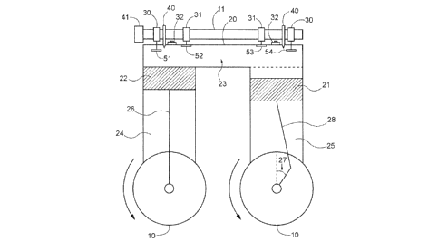
100241 FIG. 1 is a simplified schematic diagram of one embodiment of the
invention
described herein at the beginning of the intake stroke.
100251 FIG. 2 is a simplified schematic diagram of one embodiment of the
invention
described herein at the end of the intake stroke.
-7-
CA 3021866 2018-10-23
100261 FIG. 3 is a simplified schematic diagram of one embodiment of the
invention
described herein at the beginning of the compression stroke.
[0027] FIG. 4 is a simplified schematic diagram of one embodiment of the
invention
described herein at the end of the compression stroke.
[0028] FIG. 5 is a simplified schematic diagram of one embodiment of the
invention
described herein at the beginning of the power stroke.
[0029] FIG. 6 is a simplified schematic diagram of one embodiment of the
invention
described herein at the end of the power stroke.
[0030] FIG. 7 is a simplified schematic diagram of one embodiment of the
invention
described herein at the beginning of the exhaust stroke.
[0031] FIG. 8 is a simplified schematic diagram of one embodiment of the
invention
described herein at the end of the exhaust stroke.
DETAILED DESCRIPTION OF THE DRAWINGS
[0032] The embodiments of the invention and the various features and
advantages thereto
are more fully explained with references to the non-limiting embodiments and
examples that are
described and set forth in the following descriptions of those examples.
Descriptions of well-
known components and techniques may be omitted to avoid obscuring the
invention. The
examples used herein are intended merely to facilitate an understanding of
ways in which the
invention may be practiced and to further enable those skilled in the art to
practice the invention.
Accordingly, the examples and embodiments set forth herein should not be
construed as limiting
the scope of the invention, which is defined by the claims.
[0033] As used herein, terms such as "a," "an," and "the" include
singular and plural
referents unless the context clearly demands otherwise.
-8-
CA 3021866 2018-10-23
[0034] As used herein, the term "about" means within 10% of a stated
number.
[0035] FIGS. 1-4 depict a first example of rocker cams, e.g. 30 and 31,
which contact the
camshaft 11 to move the exhaust and intake valves. By contrast, FIGS. 5-8
depict push rods,
connected to the camshaft 11. Those of skill in the art will recognize that
the type of camshaft 11
can be modified to meet the needs of the particular engine. Indeed, double
overhead cams may be
utilized, each controlling exhaust of intake valves independently. Other
suitable mechanisms exist
in the art. The FIGS. 5-8 particularly show the offset nature of the camshaft
11, as will be described
in detail throughout. An Otto cycle would proceed with the following FIGS. in
order, 1-8, and
then repeating.
[0036] In each figure, the large circles at the bottom represent the
crankshaft 10, which is
shown oriented to depict the offset nature of the connecting rods. The two
circles are a single
crankshaft, simply rotated 90 degrees to depict the offset nature. Similarly,
Figures 5-8 are
showing smaller circles at the top, representing a single camshaft 11 rotated
to show the pushrods
offset. These representations are understood by those of skill in the art.
[0037] FIG. 1 is a simplified schematic diagram of one embodiment of the
invention
described herein at approximately the beginning of the intake stroke. The left
piston 22 is located
at approximately top dead center of the left cylinder 24, which is the point
closest to the cylinder
head 20. Thus, the left connecting rod 26 is approximately vertical.
[0038] The right piston 21 is offset from the left piston 22 and is
trailing. When the left
piston 22 is at top dead center, the angle 27 of offset of the right piston
21, as measured from where
the right connecting rod 28 meets the crankshaft 10, is between about 8 and 12
degrees trailing of
the right connecting rod 26. Timing of an engine is often described in
degrees, and the timing of
certain components is thus described in degrees corresponding to the timing.
Here, the parallel
-9-
CA 3021866 2018-10-23
pistons 22 and 21 and in fluid communication with one another because of the
open head space
23, and the trailing piston 21 is offset by between 8 to 12 degrees. In other
words, the connecting
rods to the crank shaft enable the trailing piston 21 to be offset from the
leading piston 22 by about
8-12 degrees. Thus. the right connecting rod 28 is not completely vertical and
the right piston 21
is before dead center in the right cylinder 25. The trailing piston will
always be the second piston,
which impacts the fuel added to the relative cylinders and the timing and
firing of the sparkplugs
32.
[0039] Indeed, as depicted, the left (leading) piston 22 and right
(trailing) piston 21 are
operated together in a single cavity, such that the space in the head opening
23 connects the two
cylinders 24 and 25. This head opening 23 is defined between the top of the
cylinder and the
bottom of the cylinder head and provides that the intake, compression, power,
and exhaust is
occurring within the two cylinders, because of their fluid communication in
this head opening 23
¨ as compared to a typical engine, where each cylinder operates independent of
other cylinders.
One advantage of the system is that where a typical engine fires before top
dead center, a portion
of the force on the cylinder is wasted and results in inefficiencies. By
pairing the two
pistons/cylinders, a single explosion within the two cylinders will begin to
affect at least one of
the pistons as it is past top dead center, therefore allowing the full force
of the explosion to push
that piston, where the trailing piston is then pulled past top dead center,
and then continues to push
down due to the explosion.
[0040] Furthermore, the pushing, and pulling of gas and fuel is greatly
improved by the
offset nature. For example, as the intake stroke continues, into the
compression stroke, as seen in
FIGS. 1-4, air enters both the left cylinder 24 and the right cylinder 26,
through the intake valves
51 and 54. The small head space 23, then moves gasses between each cylinder as
the pistons
-10-
CA 3021866 2018-10-23
rotate. As piston 21 pushes up, gas is pushed into the head space 23 and into
cylinder 24, as piston
22 rotates down towards bottom dead center. In FIG. 3, as the valves close,
and as piston 22 begins
to move up, gasses move from cylinder 24 through the open head space 23, into
cylinder 25. Gas
and air injected into the open head space 23 during the intake and/or
compression will then mix
with air and increase the burn rate of the air/fuel mixture. While a ratio of
14.7/1 is typical for a
stoichiometric air to fuel ratio, we can improve that ratio dramatically and
run the engine leaner
through this advances of the engine described herein. For example, we can run
the engine at a
ratio of 17-1 or higher between 3500 and 5000 RPM, which is not possible with
a conventional
engine. This allows for a much leaner ratio and results in significant engine
fuel efficiency.
[0041] As further defined in FIG. 1, the first cylinder 24, and the first
piston 22 is
positioned at or about top dead center and the second piston 21 within the
second cylinder 25 is
positioned just shy of top dead center, having a trailing angle or about 8 to
12 degrees. A spark
plug 32 is positioned at a central position above each of the cylinders.
Importantly, an intake valve
51 and 54 and exhaust valves 52 and 53 are positioned above each cylinder and
controlled by the
cam shafts. For example, the cam gear 41 rotating, will press the rocker cams
or other cam device
to move the valves. For example the rocker cam 30 and 31 on each cylinder. A
fuel injector 40 is
also positioned, adjacent to the spark plug 32, for direct injection into the
head space 32.
[0042] The cams 30 and 31 are necessary components to allow for the four
strokes, the
intake, compression, power, and exhaust strokes, by moving the relevant valves
51-54 to allow for
air to enter, on the intake, close for compression, close for power, and then
exhaust after the power
stroke. These valves work with a camshaft 11 that has an appropriate offset in
view of the offset
of the crankshaft 10. The camshaft 11 rotates at one-half the speed of the
crankshaft 10. However,
to properly operate, the camshaft 11 must also have an offset for the second
cylinder 25 at a rate
-11-
CA 3021866 2018-10-23
of one-half the offset of the crankshaft 10. For example, a crankshaft 10
having an offset of 8
degrees would have a camshaft offset of 4 degrees for the second cylinder.
This would then retard
the opening and closing of valves 53 and 54 by 4 degrees as compared to valves
51 and 52.
100431 Table 1:
Crankshaft offset Camshaft offset
8 4
9 4.5
5
11 5.5
12 6
100441 Table 1 depicts the range of crankshaft offset suitable for the
production engine,
and the corresponding camshaft offset.
100451 The angle of offset between the two pistons will depend on the
size of the engine.
the RPM's obtained and other features known to one of ordinary skill in the
art. In the embodiment
of FIG. 1, when the force from the explosion is applied to the pistons, the
left piston 22 is at a
mechanically superior position as compared to the right piston 21. This allows
the force being
applied to the right piston 21 to be mechanically efficient improves the
mechanical efficiency as
applied in total to the paired pistons, as compared to two individual pistons.
By allowing one
piston to always be past top dead center when firing, the combined mechanical
efficiency is
improved. However, to maintain the proper firing and compression the angle
must not be too
small, nor too large. A larger offset angle of greater than 12 degrees
resulted in a reduction in head
pressure, and thus the engine ran inefficiently. By contrast, a smaller
offset, we believe, did not
allow for sufficient mixture of fuel and air, and also reduced the head
pressure, as compared to
-12-
CA 3021866 2018-10-23
individual cylinders, and thus was also less efficient than those between
about 8 and 12 degrees
offset. This range was surprising in the significant gains seen in fuel
efficiency, as crankshafts of
less than 8 degrees when tested, ran similar to a single engine for
efficiency, just with less power
because of the reduced head pressure. Similarly, the larger angle ran even
less efficiently than the
standard engine in both power and in fuel efficiency due to the lag of the
second piston and also
due to the much larger volume at spark, thus reducing the compression and head
pressure. Thus,
the 8-12 degree range, and specifically 12 degrees was surprisingly superior.
[0046]
By adjusting the offset angle 27, the compression in the head opening 23 can
be
modified to maximize performance of the engine. Similarly, the amount of space
in the head
opening 23 can be modified to enlarge or minimize the opening space to modify
the amount of
possible compression and to allow for optimal gas exchange between the two
cylinders. However,
at no time is the head opening 23 closed; therefore, the two cylinders/pistons
are always connected
via this head opening 23 space. For example, the cylinder head 20 can be
machined to have a
single tube for gas exchange, or a larger groove. In each case, the space
should not restrict flow
to allow for the efficient exchange of gasses in each piston, while the
smaller size allows for
increased head pressure.
[0047]
Generally, a functioning engine would comprise a single pair of cylinders, or,
alternatively, two, three, or four pairs, or more pairs of cylinders to
maintain balance. The
additional cylinders may be oriented in-line, or offset in any of the
orientations known of one of
skill in the art. For conventional engines for typical use in recreational
vehicles, or for other small
scale uses, the typical engine will have one or two pairs of cylinders.
[0048]
It would be feasible to take a straight 8 cylinder, or an angled 8 cylinder
engine and
modify various components of the engine, i.e. the cylinder head 20, so as to
introduce a head
-13-
CA 3021866 2018-10-23
opening 23, as between the previously unconnected cylinders. With additional
modifications to
the connecting rods 26 and 28 and other features of the engine to form the
offset paired cylinders.
Indeed, by having an engine with 8 cylinders, each of the four pairs could be
starting one of the
four cycles of the Otto cycle, as a mechanism to balance the engine and
optimize the efficiency.
[0049)
Similarly, a four cylinder engine could have one pair beginning the firing
cycle and
the other beginning the intake cycle. Alternatively, it may be advantageous to
have each pair offset
as to another pair of cylinders.
100501
This design of this embodiment differs significantly from other designs in
which
two pistons are pushed from a single explosion via the opposing cylinder
engine. There, the pistons
fire in opposing directions. Here, the cylinders are intended to be
substantially parallel to one
another, but the pistons within the cylinders are offset. That allows for the
modification in the
head to allow for the connection of the two cylinders. The design herein
provides for a significant
advantage in operating efficiency as compared to prior art engines.
[0051]
The engine cycle is appropriately detailed through FIGS. 1-8. The relative
positions of each of the pistons and of the valves are illustrative to
describe the features, and their
specific positions may be modified as appropriate. The specific location can
also be modified
based on timing, RPM of the engine, etc., to control the power and fuel
efficiency.
[0052]
FIG. 1 specifically starts the beginning of the intake portion of the cycle.
The left
piston 22 is at top dead center and the intake valves 51 and 54 are open, to
allow for air to enter
the cylinders 24 and 25 as the crankshaft 10 rotates in a counterclockwise
manner and pulls the
left piston 22 down, with the right piston 21 following. At FIG. 2, the end of
the intake stroke, the
right piston 21 is at bottom dead center. The intake and exhaust valves are
depicted with intake
51 closed, while intake 54 is nearly closed, being that it is trailing/offset
by about 6 degrees for a
-14-
CA 3021866 2018-10-23
1 2 degree offset crankshaft. On the left side of FIG. 2, is a belt 42. The
belt may be any ordinary
belt used in engines, the belt 42 connects the crankshaft 10 to the camshaft
11. FIG. 6 also shows
this belt 42, it is otherwise omitted from other figures for clarity of the
other components within
the cycle, though it would be present in all cases.
[0053] FIG. 3 depicts the beginning of the compression stroke, where the
left piston 22 is
at approximately bottom dead center and the trailing piston 21 is nearly at
bottom dead center. All
valves 51-54 are closed, to allow for compression of the air within the
cylinders. As the crankshaft
rotates, air is compressed and pushes first from the smaller volume in
cylinder 24, through the
open head space 23 and into the greater relative volume of cylinder 25. At the
same time, or even
starting in the intake portion of FIGS. 1 and 2, fuel is injected into only
the second cylinder 25,
under routine function. The chart below provides for data regarding the
precise firing and fuel
injection into these cylinders and the relevant efficiencies.
[0054] Table 2:
Test Cylinder Ignition Fuel Air On/off Air fuel Exhaust
Number ON/off ON/Off ratio air/fuel
ratio
I 1 On On On 13.5-1 10-1
2 On On On 13.5-1
2 1 On OFF On Air only 18-1
2 On _ On On 13.5-I
3 1 OFF On On 13.5-1 17-1
2 On On On 13.5-1
4 1 On On On 13.5-1 WILL NOT
2 On OFF On Air Only RUN
5 1 On OFF On 13.5-1 17-1
2 On On On 13.5-1
[0055] Test 5 repeated Test 2, with modified timing, both advanced and
retarded ¨ and
resulted in a reduction in the efficiency, from optimal timing. Accordingly,
the optimal operating
-15-
CA 3021866 2018-10-23
procedure is defined by test 2, which indicates that no fuel is provided to
the leading cylinder, i.e.
cylinder 24 or the left cylinder in the images. Thus, all fuel is provided to
the cylinder 25 having
the trailing piston 21. Interestingly, if you swap the fuel, and have only
fuel to the leading cylinder
24, the engine stalls and will not run as shown in Test 4 in the above table.
Yet, fuel to both
chambers has the engine running rich and thus wastes fuel. This surprising
effect of fuel injection
to only the trailing cylinder leads to some of the increased fuel efficiency
we see in this engine.
[0056] At the end of the compression stroke and beginning of the power
stroke, e.g. FIGS.
4 and 5, a spark 33 is generated in each cylinder. This is provided with fuel
into the second cylinder
25 only. The spark 33 is engaged based on optimal timing of the engine,
typically as the left piston
22 has reached top dead center. This allows for the spark to ignite the
air/fuel mixture in the
compressed chamber and push the left piston 22 down, as the right piston 21
reaches top dead
center, and follows completing the cycle. As we approach FIG. 6 and FIG. 7,
the power cycle
ends and the exhaust cycle starts. In FIG. 6, the exhaust valve 52 begins to
open before the exhaust
valve 53. While in FIG. 7, both exhaust valves 52 and 53 are open. Again, this
is based on the
slight offset timing from the cam shaft, and the air and exhaust aid in the
flow of gasses within the
head space 23 to increase the efficiency of this engine.
100571 Finally, as in FIG. 8, the exhaust ends and the intake cycle again
beings, with the
intake valve 51 opening first, as air is pulled into the cylinder. In certain
embodiments, and based
on timing, both an exhaust valve and an intake valve may be open
simultaneously, or the intake
open above one cylinder, while the exhaust is open above the opposing
cylinder. The relative
timing of the valves 51-54 is illustrative, and each may open earlier or later
as defined by electronic
control systems, and variable timing systems. Accordingly, their precise
nature may different
between one Figures over another. However, their relative positions as
depicted and described are
-16-
CA 3021866 2018-10-23
understood by those of skill in the art, with the primary feature being that
the camshaft 11 is offset
by one-half of the offset of the crankshaft to allow for functioning of the
parallel paired pistons.
[0058] As defined in more detail in FIGS. 5-8, the cam gear 41 is connected
to the camshaft
11 to allow it to rotate with the crankshaft 10, for example with the belt 42.
The cam gear 41 is
indicated by additional shaft components 61 and 62, allowing for direct
connection to push rods,
or rotatable contact with valve assemblies to move the valves 51-54. These, as
described above,
are merely exemplary of the camshaft and its rotation, to show the offset
nature of the trailing
section, i.e. 62 trailing 61 by a few degrees, based upon the amount of degree
separation for the
crankshaft.
[0059] The push rods, e.g. 62 and 63 would connect to one or more feature
of the camshaft
and to the valve assemblies, to open and close the valves 51-54. In certain
embodiments, it may
be advantageous to use a crankshaft or features that are irregular shaped, so
that as they turn, a
point or a flat section will push onto the cams to open or close valves. Those
of skill in the art will
recognize the modifications necessary to enable timing for the particular
engine.
[0060] The below tests utilized an engine having an offset crankshaft of 12
degrees and an
offset camshaft of 6 degrees for the trailing cylinder. Based on the earlier
test, we recognize that
it is advantageous to not include fuel in the first cylinder. However, even
fuel in the first cylinder
was tested below for relative comparisons. Tests 2 and 3 tested the difference
with ignition and
no ignition in the first cylinder. Test 4 concluded that the engine would not
run with no fuel in the
second cylinder. Test 5 tested two further variations of Test 2, advancing
timing 7 further degrees
of firing of the spark. Test 6 is a standard engine of the same variety,
having no parallel cylinders.
Each engine orientations were tested at 3500, 4000. 4500, and 5000 RPM as
provided in as below
in Table 3:
-17-
CA 3021866 2018-10-23
,
[0061] Table 3 ¨ Air fuel ratio
Test Cylinder Ignition Fuel 1 3500 4000 RPM 4500 5000
Number ON/off ON/Off RPM RPM RPM
1 1 On On 10-1 10-1 10-1 10-1
2 On On
2 1 On OFF 18.1-1 17.7-1 17.7-1 17.9-1
2 On On
3 1 OFF OFF 17.7-1 17.7-1 18-1 17.9-1
2 On On
4 1 On On None None None None
2 On OFF
1 On OFF Advanced N/A 17.5-1 17.5-1
2 On On 7 degrees
I On OFF Advanced N/A 14.9-1 17.6-1
2 On On 15
degrees
6 Standard 14.1-1 13.9-1 13.8-1 13.7-1
engine
[0062] Accordingly, the engines of tests 2 and 3 are the leanest running
engines and thus
are optimized. This allows greater fuel efficiency over a standard engine of
the same build, and
would lead to dramatic gains in fuel economy. This is particularly surprising,
that small
modifications in the orientation as well as in the mixture of fuel into only
the trailing cylinder
would result in such dramatic improvements in fuel economy over a standard
engine. There is a
slight exchange in the fuel economy for HP. For example, the engine of Tests 2
and 3 above, ran
at about 20% reduction of horsepower as compared to the standard engine.
However, most engines
do not need the additional power, and most engines typically run nowhere near
their maximum
RPM.
-18-
CA 3021866 2018-10-23
100631 Table 4 BSFC lbs/HP-Hour
Test Cylinder Ignition Fuel 3500 4000 RPM 4500 5000
Number ON/off ON/Off RPM RPM RPM
1 1 On On 1.37 1.42 1.40 1.35
2 On On
2 1 On OFF 0.88 0.98 0.81 0.80
2 On On
3 1 OFF OFF 1.2 0.90 0.86 0.87
2 On On
4 I On On None None None None
2 On OFF
1 On OFF Advanced N/A 0.92 0.93
2 On On 7 degrees
1 On OFF Advanced N/A 1.3 0.93
2 On On 15
degrees
6 Standard 0.85 0.86 0.84 0.75
engine
[0064] The efficiency of the engine is compared here and shown to have an
increase over
standard engines. While fuel to both cylinders increases power, this would not
result in a greater
efficiency, as shown above in table 3. Accordingly, where power is needed, or
for starting, for
example, fuel may be injected into both cylinders, thus the first cylinder 24
possesses a fuel injector
40.
[0065] Accordingly, a particular feature of the invention is that a
replacement head and
replacement connecting rod, and camshaft are relatively inexpensive to
manufacture and can be
modified on an existing engine to create a modified paired cylinder engine as
described in the
various embodiments herein. Accordingly, a further embodiment of the invention
is a kit or a
system comprising a modified head having disposed openings that are situated
between a pair of
cylinders, and further comprising one or more replacement connecting rods to
augment the angle
of at least one piston in the engine, so as to pair the cylinders and create
an offset angle of between
-19-
CA 3021866 2018-10-23
8 and 12 degrees between the paired cylinders, and a camshaft enabling an
offset of between 4 and
6 degrees, corresponding to one-half of the offset of the crankshaft. The
result of the system is a
kit that can be utilized with a standard engine to modify it to having paired
cylinders. No other
similar system or kit currently exists.
100661
Although the present invention has been described in considerable detail,
those
skilled in the art will appreciate that numerous changes and modifications may
be made to the
embodiments and preferred embodiments of the invention and that such changes
and modifications
may be made without departing from the spirit of the invention. It is
therefore intended that the
appended claims cover all equivalent variations as fall within the scope of
the invention.
-20-
CA 3021866 2018-10-23