Note : Les descriptions sont présentées dans la langue officielle dans laquelle elles ont été soumises.
SEGMENTED INTERNAL FUEL MANIFOLD
TECHNICAL FIELD
[0001] The application relates generally to gas turbine engines and, more
particularly,
to an internal fuel manifold assembly.
BACKGROUND OF THE ART
[0002] An internal manifold ring mounted inside the gas generator case of a
gas turbine
engine has proven to be advantageous in terms of system weight and cost
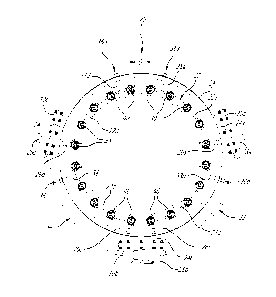
reduction.
However, the manifold ring cannot be removed for maintenance without
dismantling the
engine case components from one another to provide access to the interior of
the
engine, which is a major maintenance operation with its associated costs and
time off-
wing for the engine.
SUMMARY
[0003] In one aspect, there is provided a gas turbine engine comprising: an
engine
case having a circumferential wall defining a plenum around a combustor; at
least one
access port defined in the circumferential wall of the engine case; and a
segmented
annular fuel manifold mounted inside the engine case in the plenum, the
segmented
annular fuel manifold having a plurality of manifold ring segments, the
manifold ring
segments configured to be removable from the plenum via the at least one
access port.
[0004] In another aspect, there is provided a gas turbine engine comprising: a
combustor including a combustor shell defining a combustion chamber; an engine
case
defining a plenum around the combustor shell; an annular fuel manifold
segmented into
manifold ring segments removably mounted in the plenum; and access ports
defined in
the engine case to provide access to the manifold ring segments, the manifold
ring
segments being individually removable from the plenum via the access ports.
[0005] In a further aspect, there is provided a method for facilitating
maintenance of an
internal fuel manifold mounted inside a gas generator case of a gas turbine
engine, the
method comprising: segmenting the internal fuel manifold into manifold ring
segments;
1
CA 3031658 2019-01-25
and providing access ports in the gas generator case, the access ports being
configured to permit removal of the manifold ring segments from the gas
generator case
without splitting the engine.
[0006] In a still further general aspect, there is provided a method of
maintaining a gas
turbine engine having a segmented fuel manifold mounted inside an engine case,
the
segmented fuel manifold comprising a plurality of manifold ring segments, the
method
comprising: disconnecting a first one of the manifold ring segments from a
fuel source;
opening an access port in a side of the engine case; physically disconnecting
the first
manifold ring segment from the engine case; and removing the first manifold
ring
segment from the engine case via the access port.
DESCRIPTION OF THE DRAWINGS
[0007] Reference is now made to the accompanying figures in which:
[0008] Fig. 1 is a schematic cross-sectional view of a gas turbine engine
having a
segmented internal fuel manifold;
[0009] Fig. 2 is an isometric view of a fuel manifold assembly including a
segmented
internal fuel manifold with individually removable manifold ring segments
through
respective access ports defined in the engine gas generator case;
[0010] Fig. 3 is an end view illustrating the manifold ring segments mounted
inside the
gas generator case of the engine for supplying fuel into the engine combustor;
[0011] Figs. 4a and 4b are cross-section views illustrating how a manifold
ring segment
is first disengaged from the combustor to allow subsequent removal of the
manifold ring
segment from the gas generator case without having to split the engine; and
[0012] Fig. 5 is a further cross-section view illustrating how the manifold
ring segment
is removed from the gas generator case and pull out of the engine after having
been
disengaged from the combustor as shown in Figs 4a and 4b.
2
CA 3031658 2019-01-25
DETAILED DESCRIPTION
[0013] Fig. 1 illustrates a gas turbine engine 10 of a type preferably
provided for use in
subsonic flight, generally comprising in serial flow communication a fan 12
through
which ambient air is propelled, a compressor section 14 for pressurizing the
air, a
combustor section 16 in which the compressed air is mixed with fuel and
ignited for
generating an annular stream of hot combustion gases, and a turbine section 18
for
extracting energy from the combustion gases.
[0014] The combustor section 16 comprises a combustor having an annular
combustor
shell 19 concentrically mounted about the engine central axis 11 in a plenum
17
circumscribed by an engine case including a gas generator case 24 (Figs. 2 and
3)
detachably mounted between compressor and turbine casing sections of the
engine 10.
As can be appreciated from Fig. 1, the plenum 17 is fed with pressurized air
from the
compressor section 14. The combustor shell 19 includes a radially inner and a
radially
outer liner 19a, 19b extending axially from a combustor dome 19c to define
therewith a
combustion chamber 19d. In the illustrated example, the combustor is a reverse-
flow
combustor. However, it is understood that the combustor could be provided in
various
forms, including straight flow combustor designs.
[0015] The combustor section 16 further comprises a fuel manifold assembly 20
for
supplying fuel to the combustor. As can be appreciated from Figs 1-3, the fuel
manifold
assembly 20 comprises an annular fuel manifold 22 mounted in the plenum 17
inside
the gas generator case 24 of the engine 10 adjacent to combustor dome 19c. As
will be
seen hereinafter, the fuel manifold 22 and the engine case in which it is
installed (e.g.
the gas generator case 24 in the illustrated example) are configured to allow
the
internally mounted fuel manifold 22 to be removed (for its replacement or
maintenance)
without dismantling the engine case components from one another to provide
access to
the interior of the engine 10.
[0016] To that end, internal manifold 22 can be segmented. In the illustrated
example,
the manifold 22 consists of a plurality (4 in the illustrated example) of
rigid manifold ring
segments 22a, 22b, 22c and 22d circumferentially spaced-apart by inter-segment
gaps
G. In the illustrated example, the manifold ring segments 22a, 22b, 22c and
22d are
3
CA 3031658 2019-01-25
detachably mounted to the gas generator case 24 and individually removable
from the
plenum 17 via associated access ports 24a, 24b 24c (3 in the illustrated
example)
defined in the gas generator case 24. As shown in Figs. 2, 3 and 5, each of
the access
ports 24a, 24b, 24c can be provided in the form of a boss protruding outwardly
from the
gas generator case 24.
[0017] According to the example depicted in Figs 2 and 3, the manifold ring
segment
22a, which is located in the upper right quadrant of the gas generator case
24, can be
installed/removed via port 24a. The manifold ring segments 22b and 22c, which
are
respectively disposed in the lower right and lower left quadrants of the gas
generator
case 24 can be installed/removed via the same centrally disposed bottom port
24b.
Lastly, manifold ring segment 22d, which is disposed in the upper left
quadrant of the
gas generator case 24, can be installed/removed via port 24c.
[0018] In the illustrated embodiment, the access port 24b is centrally located
at the
bottom of the gas generator case 24 and access ports 24a, 24c respectively for
the
right and left upper quadrant manifold segments 22a and 22d are angularly
disposed or
"clocked" around the circumference of the gas generator case 24 at a same
angle from
the bottom access port 24b. However, it is understood that various segment and
port
arrangements are contemplated.
[0019] Each access port 24a, 24b, 24c defines an opening which is shaped and
size to
allow for the passage (insertion or removal) of the associated manifold ring
segment. As
can be appreciated from Figs 2 and 5, the opening defined by each access port
may
have an oblong shape configured to allow the associated manifold ring segment
22a,
22b, 22c, 22d to be angularly withdrawn from and inserted into the gas
generator case
24 while the gas generator case 24 is assembled to the compressor and turbine
casing
sections (i.e. without splitting the engine).
[0020] As can be appreciated, from Figs. 2 and 3, each of the manifold ring
segments
22a, 22b, 22c, 22d is provided at a first end thereof with a fuel inlet tube
26a, 26b, 26c,
26d projecting through the associated access port 24a, 24b, 24c in the gas
generator
case 24 for connection with an associated manifold adapter 28a, 28b, 28c
mounted to a
cover plate 30a, 30b, 30c, which is, in turn, detachably mounted to the gas
generator
4
CA 3031658 2019-01-25
case 24 over an associated one of the access ports 24a, 22b, 24c. The cover
plates
30a, 30b, 30c can be bolted or otherwise suitably detachably connected to
mounting
flanges extending about respective mouths of the access ports 24a, 24b, 24c.
[0021] The fuel inlet tubes 26a, 26b, 26c, 26d may be brazed or otherwise
rigidly
connected to the associated manifold ring segments 22a, 22b, 22c , 22d to each
form a
one-piece of hardware. For instance, metal injection molding (MIM) or additive
manufacturing (AM) could be used to form a manifold ring segment with an
integral fuel
inlet "leg". The fuel inlet tubes 26a, 26b, 26c, 26d are strategically located
at one end of
the corresponding segments 22a, 22b, 22c, 22d to facilitate the removal
thereof through
the associated access ports 24a, 24b, 24c. With their respective fuel inlet
tubes 26a,
26b, 26c, 26d the manifold ring segments 22a, 22b, 22c, 22d can be
individually
connected to a common source of fuel, thereby eliminating the need for
serially
interconnecting the segments in fluid flow communication and, thus, further
facilitating
the individual removal of the manifold ring segments 22a, 22b, 22c, 22d from
the gas
generator case 24.
[0022] In the illustrated embodiment, the manifold adapters 28a and 28c
respectively of
manifold ring segments 22a and 22d are fluidly connected to the dual manifold
adapter
28b of manifold ring segments 22b, 22c. More particularly, the bottom manifold
adapter
28b may have an inlet connected to the source of fuel, first and second
outlets
respectively connected to manifold segments 22b and 22c, a third outlet
connected to
fuel adapter 28a of the manifold ring segment 22a via a first external fuel
line 30, and a
fourth outlet connected to the fuel adapter 28c of the fourth manifold ring
segment 22d.
It is understood that each fuel line 32, 34 may include primary and secondary
fuel
conduits, as shown in Fig. 2. Also, each manifold adapters 28a, 28b, 28c could
be
directly operatively connected to the fuel source. Furthermore, the external
fuel system
can be designed in such a way that all manifold ring segments 22a, 22b, 22c
and 22d
are pressurized simultaneously to reduce engine start up time.
[0023] Each manifold ring segment 22a, 22b, 22c, 22d is detachably supported
at a
second end thereof opposite the fuel inlet tube 26a, 26b, 26c, 26d by
respective support
structures 36a, 36b, 36c, 36d depending radially inwardly from the gas
generator case
CA 3031658 2019-01-25
24. Accordingly, each manifold ring segment 22a, 22b, 22c, 22d has two points
of
support, a first point of support provided by its fuel inlet tube 26a, 26b,
26c, 26d and a
second point of support provided by the support structure 36a, 36b, 36c, 36d.
As
shown in the illustrated example, each support structure 36a, 36b, 36c, 36d
can take
the form of a locating pin engageable with attachment point in the second end
of the
associated manifold ring segment 22a, 22b, 22c, 22d. For instance, the
locating pin
could be threadably engageable in a corresponding threaded hole at the second
end of
the manifold segment. The locating pins can be engaged in respective tubular
structures 38a, 38b, 38c, 38d provided on the gas generator case 24 at
predetermined
distance from the access ports 24a, 24b, 24c, 24d. In some applications, the
tubular
structures can be omitted. The locating pin could be mounted directly to the
gas
generator case 24. It is understood that other support arrangements are
contemplated
to detachably mount the manifold ring segments 22a, 22h, 22c, 22d inside the
gas
generator case 24.
[0024] Each of the manifold ring segments 22a, 22b, 22c, 22d may act as a
single
nozzle that has several injection points. For instance, each of the manifold
ring
segments 22a, 22b, 22c, 22d may be manufactured in the form of a rigid ring
segment
having an internal fuel conduit, which may include primary and secondary fuel
passages, for feeding a series of injection heads 40 uniformly distributed
along the
length of the rigid ring segment. The injection heads 40 can, for instance,
take the form
of nozzle tips brazed in corresponding seats defined in the front face of the
ring
segment for projecting into corresponding injection holes 19e (Fig. 2)
circumferentially
distributed in the combustor dome 19c. This configuration allows having
various
combinations of duplex and simplex fuel injectors in one segment. Usage of MIM
or AM
technologies allows creating complex segment shapes, which can be optimized
for
weight and/or cooling purposes.
[0025] As compared to a full ring manifold design, the segmented configuration
also
allows to reduce the fuel "travel" time required to reach the last nozzle tip,
thereby
reducing heat gain by the fuel inside the manifold 22. This may lead to better
fuel
manifold and nozzle tip durability.
6
CA 3031658 2019-01-25
[0026] Referring now to Figs. 4a, 4b and 5, there will be described the
procedure for
servicing the internal fuel manifold and more particularly the procedure for
removing
one manifold ring segment, the same procedure being followed for each manifold
ring
segment to be serviced or replaced. First, as shown in Figs. 4a and 4b with
respect to
manifold ring segment 22d, the first step consist of disengaging the manifold
ring
segment 22d from the combustor. In order to do so, the fuel inlet tube 26 is
disconnected from its adapter 28c and the cover plate 30c covering access port
24c is
removed, thereby providing access to the manifold ring segment 22d via access
port
24c. The locating pin 36d (or any other support structure used) is uncoupled
from the
manifold ring segment 22d and pulled out of tubular structure 38d. While
holding the
manifold ring segment 22d by its fuel inlet tube 26d, the manifold ring
segment 22d is
axially moved away from the combustor dome 19c by a distance sufficient to
move the
nozzle tips 40 out of the injection holes 19e, as shown in Fig. 4b. Then, in a
second
step, the manifold ring segment 22d is removed from the gas generator case 24
via the
uncovered access port 24c as shown in Fig. 5. This can be done by pivoting the
manifold ring segment 22d so as to generally longitudinally align the segment
in the
access ports 24c as the same is being pulled out by its inlet end from the gas
generator
case 24, as depicted in Fig. 5.
[0027] Similar procedures are followed for the other manifold ring segments
22a, 22b,
22c. Accordingly, the internal fuel manifold 22 can be completely removed and
replaced
either with new segments or repaired segments without splitting the engine.
This
simplifies the maintenance procedures and reduces the time required for the
maintenance of an internal fuel manifold.
[0028] According to one aspect, the present disclosure provide for a method
for
facilitating maintenance of an internal fuel manifold mounted inside a gas
generator
case of a gas turbine engine. The method comprises segmenting the internal
fuel
manifold into manifold ring segments; and providing access ports in the gas
generator
case, the access ports being configured to permit removal of the manifold ring
segments from the gas generator case without splitting the engine. The fuel
inlet of
each segment may be strategically located closer to one end of the segment to
facilitate
7
CA 3031658 2019-01-25
removal of the segment. The ability of removing the segments without splitting
the
engine facilitates the maintenance of internal manifolds.
[0029] The above description is meant to be exemplary only, and one skilled in
the art
will recognize that changes may be made to the embodiments described without
departing from the scope of the invention disclosed. For instance, the number
of access
ports can vary depending on the applications. It might be possible to have a
single
access port. All the segments could be removed via the same port. Also, more
than one
segments could potentially be removed at a time from an access same port.
According
to another embodiment, at least some of the segments could be fluidly
connected to
one another. Also one fuel adapter could be used to feed all segments.
Furthermore,
the number of segments and number/type of nozzle tips for each segment may
vary.
Lastly, the sequence of fuel delivery for each segment may vary depending on
the
requirements of each application. Modifications which fall within the scope of
the
present invention will be apparent to those skilled in the art, in light of a
review of this
disclosure, and such modifications are intended to fall within the appended
claims.
8
CA 3031658 2019-01-25