Note : Les descriptions sont présentées dans la langue officielle dans laquelle elles ont été soumises.
CA 03034765 2019-02-22
Method for processing a signal arising from coherent
lidar and associated lidar system
FIELD OF THE INVENTION
The invention relates to the field of frequency-
modulated coherent lidars, which are for example used
for long-range target detection.
PRIOR ART
The principle of coherent lidar is well known in the
art and illustrated in figure 1. A coherent lidar
comprises a coherent source L, typically a laser that
emits a coherent light wave (in the IR, visible or
near-UV domain), an emitting device DE that allows a
volume of space to be illuminated, and a receiving
device DR, which collects a fraction of the light wave
backscattered by a target T. The Doppler frequency
shift vpop of the backscattered wave depends on the
radial velocity v of the target T.
On reception, the received backscattered light wave S
of frequency fs and a portion of the emitted wave,
referred to as the local-oscillator wave OL, are mixed.
The interference between these two waves is detected by
a photodetector D, and the electrical signal output
from the detector has an oscillating term referred to
as the beat signal Sb, in addition to terms
proportional to the received power and to the local-
oscillator power. A processing unit UT digitizes this
signal and extracts therefrom information on the
velocity v of the target T.
Preferably, the processing unit electronically filters
the beat signal Sb in a narrow band centered on the
zero frequency, in the absence of frequency shift (see
below).
CA 03034765 2019-02-22
- 2 -
For coherent lidars, the emitting and receiving devices
preferably use the same optic (monostatic lidar). This
feature allows a good mechanical stability to be
obtained and allows the influence of atmospheric
turbulence over long distances to be decreased, the
propagation paths of the incident and backscattered
waves being the same.
One solution for lidar velocimetry/rangefinding
consists in producing a system that is able to
implement frequency modulation. This technique, which
is commonly used in radar, is currently of particular
interest on account of the progress that has been made
with fiber-based laser sources. By virtue of the
frequency modulation, a time/frequency analysis allows
the distance d of the target and its velocity v to be
determined. This type of lidar also allows a laser
anemometry function to be performed.
An example of an optical architecture for a frequency-
modulated lidar 20 is illustrated in figure 2. The
coherent source is modulated in frequency so that the
frequency of the local oscillator is modulated with a
preset function referred to as the waveform, which is
controlled by the WFC module, which is synchronized
with the processing unit UT.
The optical signal that is emitted is amplified by an
amplifier EDFA, and the emission and reception use the
same optic 0 and are separated using a circulator C.
This optical signal may optionally be shifted in
frequency, for example using an acousto-optical
modulator that is preferably positioned before the
amplifier EDFA but that may also be positioned on the
path of the local oscillator. In this case, the
electronic filtering in the processing unit is carried
out about the shift frequency. A delay une LR allows
the optical paths of the local oscillator and of the
emission signal to be equalized so as to filter, in the
RF domain, defects in the optical components placed
after the amplifier EDFA (cross talk of the circulator
CA 03034765 2019-02-22
- 3 -
C, imperfections in the antireflection coatings of the
emission/reception optic 0, etc.).
An example of a coherent frequency-modulated lidar is
described in the document "Lidar systems for precision
navigation and safe landing on planetary bodies" Farzin
Amzajerdian et al, Proc. SPIE 8192, International
Symposium on Photoelectronic Detection and Imaging
2011: Laser Sensing and Imaging; and Biological and
Medical Applications of Photonics Sensing and Imaging,
819202 (August 19, 2011). Figure 3 illustrates the
operating principle of this lidar.
In the description below, the case where the optical
emission frequency and the frequency of the local
oscillator are flot shifted using an acousto-optical
modulator is described. The frequency fol, of the local
oscillator is modulated linearly with two frequency
slopes a() and al periodically with a period TF0. This
optical frequency foL may be written as the sum of a
constant optical frequency f0 (here the initial
frequency of the laser) and a time-dependent modulation
frequency frnod(t) in the radio frequency domain, which
frequency is generated by modulating the laser source:
foL(t)=f0+f,,,,d(t)
Figure 3 illustrates the variation over time in the
frequencies foL(t) and fs(t), the optical frequency f0
having been subtracted for greater clarity. As
illustrated in figure 3a, the backscattered signal of
frequency fs(t) is shifted temporally by a time T
because of the propagation to the measurement zone
(target T) and therefore related to the distance d of
the target, and is shifted in frequency by a value "VDop
because of the Doppler effect with respect to the
local-oscillator frequency foL(t).
The detected beat signal Sb has a frequency component
fs-foL. Figure 3b illustrates the variation over time in
fs-foL. It may be seen that this frequency difference
comprises as a function of time two series of plateaus
at the characteristic frequencies vc,0 and val, which
CA 03034765 2019-02-22
- 4 -
characteristic frequencies are directly related to the
distance D of the target and to its radial velocity v
by the equations:
2v 2a0D 2v 2a1D
V, and v, =7-
By measuring these two characteristic frequencies yea,
and vo,' of the beat signal Sb, for example by carrying
out a Fourier transform thereon, d and v may be
determined.
However, when the distance to the target leads to a
time-of-flight longer than the duration of the waveform
TFO normalized by the number of frequency slopes (2 in
the example), direct analysis by Fourier transform
yields unsatisfactory results. Specifically, the mixing
of the local oscillator and of the backscattered signal
leads to the disappearance of the plateaus and to a
constantly variable instantaneous frequency that, after
analysis by Fourier transform, will yield no peaks.
An example of this effect is illustrated in figure 4,
for a local-oscillator modulation with two frequency
slopes a() = 2 MHz/ps and ai = -2 MHz/11s, and a target
moving at a velocity of 30 m/s.
Figure 4a illustrates the temporal variation in fs with
respect to fol, and the frequency component of Sb fs-fol,
for a distance d of 1800 m, figure 4b showing the same
for a distance d of 14000 m and figure 4c the same for
a distance d of 20000 m.
In this case, the range of the lidar is therefore
limited by the processing of the signal whatever the
power of the laser. It is theoretically possible to
lengthen the modulation period TFO of the waveform, but
since the modulation range of certain lasers is
limited, this lengthening does net allow a high
resolution to be simultaneously achieved at long
distance. Specifically, given the limited modulation
bandwidth of the laser, it is possible to increase the
period TFO while decreasing the frequency slopes in
order to cover the same modulation bandwidth. In this
CA 03034765 2019-02-22
- 5 -
case, frequency plateaus will exist at longer distances
but, for a Fourier-transform duration TFFT that is
constant and shorter than the modulation frequency TFo,
the modulation bandwidth covered during TFFT will be
smaller and therefore the longitudinal resolution,
which is proportional to this bandwidth, will be
degraded.
One aim of the present invention is to remedy the
aforementioned drawbacks by providing a beat-signal
processing method allowing this limitation to be
overcome by allowing a signal having characteristic
frequency plateaus to once again be obtained.
DESCRIPTION OF THE INVENTION
One subject of the present invention is a method for
processing a signal generated by a coherent lidar
comprising a coherent source that is periodically
modulated in frequency,
- a beat signal being generated by a photodetector from
the interference between an optical signal referred to
as the local oscillator, having a local-oscillator
frequency, and an optical signal backscattered by a
target illuminated by the lidar, said beat signal being
digitized,
- the local-oscillator frequency consisting of the sum
of an average value and of a modulation frequency that
is generated by modulating the source, the modulation
frequency being periodic with a modulation period, each
period comprising n linear portions having n frequency
slopes, respectively, n being higher than or equal to
2,
the method comprising steps of:
- modulating in a complex way the beat signal with the
modulation frequency in order to obtain a modulated
signal,
- demodulating in a complex way the modulated signal
with n demodulation frequencies each having a single
CA 03034765 2019-02-22
- 6 -
slope equal to the respective frequency slope of the
modulation frequency, in order to obtain n demodulated
signais,
- determining n spectral densities of the n demodulated
signais,
- determining n
characteristic frequencies
corresponding to the maximum of the n spectral
densities, respectively,
- determining information on the velocity and
information on the distance of the target from said n
characteristic frequencies.
According to one embodiment, the step of determining
each spectral density comprises substeps of:
- determining a plurality of elementary spectral
densities for a plurality of time intervals shorter
than or equal to the modulation period,
- determining said spectral density from the sum of the
plurality of elementary spectral densities.
Preferably, each elementary spectral density is
determined by fast Fourier transform or FFT, and the
spectral density is equal to an average of the
elementary spectral densities.
Advantageously, each demodulation frequency is periodic
with the modulation period.
Advantageously, the frequency slopes are indexed by an
index i varying from 0 to n-1 and wherein each
demodulation frequency having a slope of index i is
temporally shifted with respect to the modulation
frequency by a shift time that is dependent on i, on n
and on the modulation period.
According to one variant, the waveform comprises 4
slopes cx0, ai, ca, cx3 with:
al = - cx0 and cx3 = - cx2
The invention also relates to a coherent lidar system
comprising:
CA 03034765 2019-02-22
- 7 -
- a coherent source that is periodically modulated in
frequency,
- a device for emitting an optical signal generated by
the coherent source and a device for receiving a signal
backscattered by a target that is illuminated by the
lidar,
- a photodetector configured ta generate a beat signal
from the interference between an optical signal
referred ta as the local oscillator, having a local-
oscillator frequency, and the backscattered optical
signal, the local-oscillator frequency consisting of
the sum of an average value and of a modulation
frequency that is generated by modulating the source,
the modulation frequency being periodic with a
modulation period, each period comprising n linear
portions having n frequency slopes, respectively, n
being higher than or equal to 2,
- a processing unit configured ta:
* digitize the beat signal,
* modulate in a complex way the beat signal with
the modulation frequency in order ta obtain a
modulated signal,
* demodulate in a complex way the modulated signal
with n demodulation frequencies each having a
single slope equal ta the respective frequency
slope of the modulation frequency in order ta
obtain n demodulated signals,
* determine n spectral densities of the n
demodulated signals,
* determine n characteristic frequencies
corresponding ta the maximum of the n spectral
densities, respectively,
* determine information on the velocity and
information on the distance of the target from
said n characteristic frequencies.
Preferably, the processing unit is furthermore
configured ta determine, for each spectral density, a
plurality of elementary spectral densities for a
CA 03034765 2019-02-22
- 8 -
plurality of time intervals shorter than or equal to
the modulation period, said spectral density being
determined from the sum of the plurality of elementary
spectral densities.
Advantageously, each elementary spectral density is
determined by fast Fourier transform, and wherein the
spectral density is equal te an average of the
elementary spectral densities.
Advantageously, the processing unit comprises n
channels, one channel per slope, each channel operating
in parallel with the others and being configured te
determine the associated frequency.
Other features, aims and advantages of the present
invention will become apparent on reading the following
detailed description with reference te the appended
drawings, which are given by way of nonlimiting
example, and in which:
Figure 1, which has already been described, illustrates
the principle of a coherent lidar.
Figure 2, which has already been described, illustrates
an example of an optical architecture for a frequency-
modulated lidar.
Figure 3a, which has already been described,
illustrates the variation over time in the frequencies
foL(t) and f.(t). Figure 3b, which has already been
described, illustrates the variation over time in fs-
f OL -
Figure 4a, which has already been described,
illustrates the temporal variation in fs with respect
te fol, and the frequency component of Sb fs-fol, for a
distance d of 1800 m, figure 4b showing the same for a
distance d of 14000 m and figure 4c the same for a
distance d of 20000 m.
CA 03034765 2019-02-22
- 9 -
Figure 5 illustrates the method for processing the
signal generated by a coherent lidar according to the
invention.
Figure 6 schematically shows a periodic waveform of a
modulation frequency fmod(t) as a function of time, said
waveform consisting of a sequence of 4 slopes a0, al,
a2 and a3.
Figure 7 illustrates the case of a target moving with a
velocity of 40 m/s at a distance of 12 km, the waveform
of the signal fmod comprising 2 slopes a() = 0.2 MHz/us
and al = -0.2 MHz/ps for an average laser frequency of
1.55 um.
Figure 7a illustrates the variation as a function of
time in the local-oscillator frequency foL(t) and in the
signal frequency fs(t). Figure 7b illustrates the two
frequency components of the lidar beat signal Sb, fs-fol,
and foL-fs. Figure 7c illustrates the variation as a
function of time in the frequency of the obtained
modulated signal Smod. Figures 7d and 7e illustrate the
variation as a function of time in the demodulation
frequencies fmod(0) (for slope a0) and fmod(1) (for slope
al), respectively. Figures 7f and 7g illustrate the
variation as a function of time in the demodulated
signal Sdemod(0) and Sciemod(1) , respectively.
Figures 8a and 8b illustrates the spectral densities
SP(0) (figure 8a) and Spi (figure 8b) of the spectra
determined from the signais Sdemod(0) and Sdemod(1).
Figure 9 is equivalent to figure 7 but for a target
located at a distance of 18 km. Figure 9a illustrates
the variation as a function of time in the local-
oscillator frequency foL(t) and in the signal frequency
fs(t). Figure 9b illustrates the two frequency
components of the lidar beat signal Sb, fs-fol, and fol,-
fs. Figure 9c illustrates the variation as a function
of time in the frequency of the obtained modulated
signal Smod. Figures 9d and 9e illustrate the variation
as a function of time in the demodulation frequencies
frnod(0) (for slope a0) and fmod(1) (for slope al),
CA 03034765 2019-02-22
- 10 -
respectively. Figures 9f and 9g illustrate the
variation as a function of time in the demodulated
signal Sdemod(0) and Sdemod(1), respectively.
Figure 10a illustrates the variation over time in the
frequencies foL(t) and fs(t), and figure 10b illustrates
the variation over time in fs-fol, for the case where fmod
has 4 slopes.
Figure lia illustrates the variation over time in the
frequencies foL(t) and fs(t), figure llb illustrates the
two frequency components of the lidar beat signal Sb,
fs-fol, and foL-fs, and figure 11c illustrates the
variation as a function of time in the frequency of the
obtained modulated signal Smod for a waveform comprising
4 slopes.
Figures 12a, 12b, 12c and 12d illustrate the variation
as a function of time in the demodulation frequencies
fmod(0) (for slope a0) and fmod(1) (for slope 1), fmsd(2)
(for slope a2) and fmod(3) (for slope a3), respectively
and figures 12e, 12f, 12g and 12h illustrate the
variation as a function of time in the demodulated
signal Sdemod(0 ) r Sdemod (1) / Sdemod (2) and
Sdemod(3),
respectively.
Figure 13 schematically shows a lidar system according
to the invention.
Figure 14 illustrates an example of implementation of a
parallel architecture in the processing unit of the
lidar according to the invention.
DETAILED DESCRIPTION OF THE INVENTION
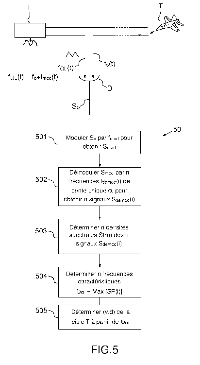
The method 50 for processing the signal generated by a
coherent lidar according to the invention is
illustrated in figure 5. The coherent lidar comprises a
coherent source L that is periodically modulated with
an RF signal. The RF modulation may be achieved
directly via the injection current of the laser or via
an exterior component. By RF what is meant is a wave
CA 03034765 2019-02-22
- 11 -
having a frequency comprised between 1 Hz and 10 GHz,
and preferably between 0.1 kHz and 10 MHz.
A beat signal Sb is generated by a photodetector D from
the interference between an optical signal, referred to
as the local oscillator OL, having a local-oscillator
frequency foL(t), and an optical signal fs(t)
backscattered by a target T illuminated by the lidar.
The beat signal is digitized in order to be processed.
The local-oscillator frequency foL(t) consists of the
sum of an average value f0 and of a modulation
frequency fmod(t) that is generated by modulating the
source.
FOL (t) =f0+fmod (t)
When no shifting acoustic modulator is used, the
frequency f0 is equal to the initial optical frequency
of the source L. When the signal OL is shifted in
frequency by an acousto-optical modulator, the
frequency f0 is equal to the optical frequency of the
source shifted.
The modulation frequency is periodic
with a
modulation period TFo, and originates from the periodic
RF modulation of the source, but is not equivalent to
the latter, because of the non-linear behavior of the
laser. Typically, the period TFO is comprised between 1
ns and one second, and preferably between 100 ns and 10
ms.
In order for the method according to the invention to
work correctly, the modulation frequency fmod(t) must be
such that each period comprises n linear portions, i.e.
n frequency slopes ai, with i an index varying from 0
to n-1, that meet at apexes. The number of slopes n is
higher than or equal to 2.
Advantageously, n is even, because, as specified below,
this allows the signs of the slopes ai to be alternated
and the signal processing to thus be simplified.
In practice, given the modulation frequency bandwidth
accessible to current lasers, it is difficult to obtain
CA 03034765 2019-02-22
- 12 -
acute angles at these apexes, and the latter are
generally rounded, as illustrated in figure 6 for a
frequency fmod(t) consisting of a sequence of 4 slopes
a0, al, a2 and a3. The form of the modulation signal of
frnod over a period TF0 is referred to as the waveform.
Preferably, the slope of index i+1 has the
opposite
sign to the slope of index i al. This allows the
frequency band covered to be narrowed while maintaining
the same fraction of the period TF0 for each slope (and
therefore the same order of magnitude of une intensity
for each frequency slope).
Preferably, the slopes of uneven indices are equal to
the opposite of the slopes of even index.
For a signal fmod with two slopes al = -a0
For a signal frnod with four slopes al = -a0 and a3 = -a2
In the latter case, the waveform may be divided into
four equal portions (leading to four lines of similar
intensity) without recourse being made to frequency
discontinuities. Preferably, the slopes ai are
comprised between 0.1 MHz/ps and a few hundred MHz/ps.
It will be noted that it is not easy to obtain a local-
oscillator optical frequency that is modulated with a
sequence of preset linear slopes such as illustrated in
figure 6. To do this it is necessary to pre-correct the
RF modulation signal of the source, as for example
described in patent application FR No. 1500603. For the
application of the invention, the waveform of frnod is
assumed known with a decent precision.
Before the steps of the method 50 according to the
invention are described, the terminology employed will
be defined.
The operation consisting in adding a frequency to an
initial signal is referred to as modulation and the
operation consisting in subtracting a frequency from
the initial signal is referred to as demodulation. Thus
modulating at +f is equivalent to demodulating at -f
and vice versa.
CA 03034765 2019-02-22
- 13 -
In the time domain, modulation or demodulation consists
in multiplying an initial temporal signal SO(t) by a
number, which is a real number for a real
modulation/demodulation (a cosine) and a complex number
for a complex modulation/demodulation.
For example, modulating in a complex way with a
frequency f is equivalent to multiplying SO(t) by
exp(2jnft). Likewise demodulating in a complex way with
a frequency f is equivalent to multiplying SO(t) by
exp(-2jnft).
When the frequency f(t) is a function of time, it is
recommended to multiply by exp[211rfotf(u)du] for a
modulation and by exp[-21rrfotf(u)du] for a demodulation.
The method 50 according to the invention consists of
specific digital processing of a signal generated by a
coherent lidar, to determine information on the
velocity and on the distance of a target illuminated by
the lidar. More particularly, the method is applicable
to the processing of the lidar beat signal Sb. The
first steps of the method are illustrated in figure 7
for the case of a signal fmod having two slopes a0 and
al.
The method 50 according to the invention comprises a
first step 501 consisting in modulating in a complex
way the beat signal Sb with the modulation frequency
fmod in order to obtain a modulated signal S.d.
Figure 7a illustrates the variation as a function of
time in the local-oscillator frequency foL(t) and in the
signal frequency fs(t), the average optical frequency
f0 having been subtracted for greater clarity.
Figure 7b illustrates the two frequency components of
the lidar beat signal Sb, fs-fol, and foL-fs.
Specifically, since it is real, it has a positive
frequency component and a negative frequency component.
Figure 7c illustrates the variation as a function of
time in the frequency of the obtained modulated signal
Smod. The real lidar beat signal Sb is modulated in a
CA 03034765 2019-02-22
- 14 -
complex way digitally with a frequency associated with
the waveform, i.e. foL-f0, where f0 is the average
frequency of the laser source L. An instantaneous
frequency is then reconstructed for the modulated
signal Smod, this instantaneous frequency corresponding
to:
fs-foL + (f0L-f0) = fs-f0
foL_fs + (foL-f0) = 2fol, - f0 - fs
Next, a step 502 consists in demodulating in a complex
way the modulated signal Smod with n demodulation
frequencies f
¨demod () having a single slope equal to one
frequency slope ai of the modulation frequency frnod,
respectively, in order to obtain n demodulated signais
Sdemod ( ) Thus n complex demodulations are applied using
n digital signais fdemod(i) of single slope ai.
To take into account the periodicity of the waveform,
it is recommended to regularly return to zero. The
demodulation frequencies f demod ( are preferably
periodic with a multiple of TFO, and preferably have a
period equal to TFO. This equality makes it possible to
make the frequency plateaus (and therefore the unes,
after spectral analysis) of the various analyzed
waveform periods coincide: for each frequency slope ai,
the associated line will appear at the same frequency
ved and, therefore, the energy associated with a target
signal will be concentrated in the same une after
time-frequency analysis.
Figures 7d and 7e illustrate the variation as a
function of time in the demodulation frequencies f.1(0)
(for slope a0) and fmod(1) (for slope al), respectively.
In order to reset the various frequencies, the
demodulation frequency of index i (corresponding to a
slope ai) is shifted by a shift time tdi that is
dependent on i, on n and on the modulation period TFO.
Preferably, the shift time is equal to:
tdi = i/n*TF0
CA 03034765 2019-02-22
- 15 -
Thus, for 2 slopes fmod(0) is flot shifted and fmod(1) is
shifted by TF0/2 (see figure 7e).
Figures 7f and 7g illustrate the variation as a
function of time in the demodulated signal Sdemod(0) and
Sdemod (1), respectively.
Each demodulation corresponds to the search for the
signal of interest in ail of the distance boxes. A
plateau of characteristic frequency val is then found in
the demodulated signal of index i. For the case of 2
slopes, Sdemod(0) allows vao to be determined whereas
Sdemod (1) allows vcd_ to be determined. The frequency val
corresponds to the offset, measured at a time for which
fs(t)-f0 has a frequency slope ai, between the
demodulation frequency fmod(i) and the frequency fs(t)-
f0, itself having been reconstructed using the
modulation of the beat signal with the frequency foL-f0.
Each frequency voa corresponds to the offset, measured
at a time for which fs(t)-f0 has a frequency slope ai,
between the demodulation frequency fmod(i) and the
frequency fs(t)-f0, itself having being reconstructed
using the modulation of the beat signal with the
frequency foL-f0.
In figure 7f, the widest plateau corresponds to +vao
whereas the narrower plateau corresponds to
Specifically, the demodulation function is tailored to
the frequency of interest, here +v,õ0 (radial velocity of
the target positive). In the same way in figure 7g, the
widest plateau corresponds to whereas the
narrower
plateau corresponds to -val.
In order to measure these characteristic frequencies,
the method 50 according to the invention also comprises
a step 503 of determining n spectral densities SP(i) of
the n demodulated signals Sdemod(i). It is a question of
carrying out a time/frequency analysis, i.e. a
frequency transform of the signal Sdemod(i) (t), in order
to make the characteristic frequency va, appear in the
form of peaks. Advantageously, it is possible to
include a temporal windowing that depends on the
CA 03034765 2019-02-22
- 16 -
analysis distance range and on the analysis frequency
slope.
Figure 8 illustrates the spectral densities SP(0)
(figure 8a) and SP(1) (figure 8b) of the spectra
determined from the signais Sdemod(0) and Sdemod(1). The
sought characteristic frequency vai has the highest
spectral density. A weaker peak is found at the
opposite frequency. A negative peak at the zero
frequency is due to filtering of the signal at low
frequencies.
Next, the method according to the invention comprises a
step 504 of determining the n characteristic
frequencies val corresponding to the maximum of the n
spectral densities SP(i), respectively. Specifically,
the frequency having the widest plateau in the signal
Sdemod/i which corresponds to the sought
characteristic frequency, is the frequency having the
highest spectral density.
A second plateau of less substantial duration (and
therefore leading to a less intense une after spectral
analysis) is also present but the corresponding
frequency has a lower spectral density than that of the
characteristic frequency. This signal originates from
the modulations and demodulations described above on
the other component of the beat signal, i.e. the
component generated by the real detection (negative
frequency component if the target signal corresponds to
a positive frequency or, conversely, positive frequency
component if the target signal corresponds to a
negative frequency).
Lastly, the method 50 comprises a step 505 of
determining information on the velocity y and
information on the distance D of the target T from said
n characteristic frequencies va, using the formula:
2v 2a1D
11,, =
A
For 2 frequency slopes:
2v 2a0D 2v 2aID
= ¨ ¨ va¨and y_ =
,,-,
CA 03034765 2019-02-22
- 17 -
It will be noted that the above formulae are valid when
the frequency of the laser is flot shifted by an
acousto-optical modulator. When such is the case, where
friA0 is the frequency shift, the characteristic
frequencies are calculated with the formula:
2v 2a1D
Va = [MAO
The invention is of course compatible with such a shift
provided that step 505 of determining d and v from the
values of the characteristic frequencies is adapted
accordingly.
Figure 7 corresponds to a target moving with a velocity
of 40 m/s at a distance of 12 km, and the waveform of
the signal fmod comprises 2 slopes a0 - 0.2 MHz/ps and
al = -0.2 MHz/ps for an average laser frequency of 1.55
pm, i.e. 193.41 THz. The period TF0 is equal to 532 us.
The detected characteristic frequencies are yod) = 35.6
MHz and val - 67.6 MHz. For Smod(0), a weaker peak
remains at -35.6 MHz and for Smod(1) at -67.6 MHz
corresponding to the narrowest plateau.
Figure 9 is equivalent to figure 7 but for a target
located at a distance of 18 km.
Figure 9a illustrates the variation as a function of
time in the local-oscillator frequency foL(t) and in the
signal frequency fs(t).
Figure 9b illustrates the two frequency components of
the lidar beat signal Sb, fs-foL and foL-fs.
Figure 9c illustrates the variation as a function of
time in the frequency of the obtained modulated signal
Smod =
Figures 9d and 9e illustrate the variation as a
function of time in the demodulation frequencies fmod(0)
(for slope a0) and fmod(1) (for slope al), respectively.
Figures 9f and 9g illustrate the variation as a
function of time in the demodulated signal Sdemod(0) and
Sdemod(1) , respectively.
It may be seen that the plateaus reappear, even at
longer distance. The detected
characteristic
CA 03034765 2019-02-22
- 18 -
frequencies are vo = 27.6 MHz and vcd_ = 75.6 MHz. There
are almost no peaks left at -27.6 MHz and -75.6 MHz
Thus, the proposed method avoids testing ail the
distance boxes (computationally expensive solution) and
allows, via a simple modulation/demodulation operation,
the distance of the target to be determined, provided
that the power of the laser remains sufficient. The
peaks generated from the backscattered signal reappear,
thus allowing a method that is no longer limited by the
processing of the signal, but solely by the power of
the laser, to be obtained.
The computation is performed on the basis of the
digitized beat signal Sb(t) as time passes.
Mathematically, step 501 of modulating with the
frequency
fmod (t ) =foi, (t ) -f0
amounts to multiplying the signal Sb(t) by a complex
number C(t), which is also digitized, equal to:
C = exp[217 fot(foc(u) ¨ fo)dui = exp[21n- fot(fmod(u))dul
That is, Smod(t) = C*Sb(t)
f0: frequency of the laser without modulation
frequency of the local oscillator
Next, in the demodulating step 502, each demodulation
amounts to multiplying the signal Smod(t) by a complex
number Ci(t) defined as follows:
= exp 1----2jn- fot [a = (u ¨ (-71'2 g (u) + f Io or (-1+21)) * ¨F¨T 2 )] du)
Where i is the index of the slope ai, with i varying
from 0 to n-1,
TF0 is the period of the waveform,
4u 30 gi(u) = floor (¨ i
nTF0¨
)
floor being the round-down function (for example
floor(2.6) = 2 and floor(-3.2) = -4)
That is, in the end:
CA 03034765 2019-02-22
- 19 -
Sciernodli(t) Sb(t). exp (2jrr fot {foL(u) fo n
ai = ¨ (-2g
floor (¨i+1))* F=97 )1cluj
2 2
n
Sciernod/i(t) = s(t). exp f2jrt- f l o
[fmod(u) ¨ = (u ¨ g i(u) + floor (-2)) *
IT2)1 du)
The portion (du corresponds to the linear portion, the
portion n/2.gi(u).TF0/2 expresses the regular return to
zero and the time shift, and the portion
floor(i+1/2) *TF0/2 corresponds to a shift in frequency
allowing a situation in which the velocity and distance
of the target are zero to be shifted to zero frequency.
The latter shift in frequency compensates for a
parasitic effect generated by the time shift associated
with the function g (u)
It will be noted that if the apexes of the waveform are
rounded, these equations remain valid because this
rounded shape is taken into account in the definition
of Srnod(t).
Step 503 of obtaining the spectral densities SP(i) is
typically carried out by frequency transform, by taking
the square of the modulus of the Fourier transform of
the temporal signal Sdemodh(t) :
2
S(v) = IF FT 1S demod(011 = F FT fSb(t). exp{2j7
fot (frnoci(u) ¨ ai =
2
(u¨ g i (u) + floor (¨i+21)) * 2L-T 21) dull
Preferably, the step 503 of determining each spectral
density comprises substeps of:
- determining a plurality of elementary spectral
densities for a plurality of time intervals bt shorter
than or equal to the modulation period TFo,
determining each spectral density of index i SP(i)
from the sum of the plurality of elementary spectral
densities.
Preferably, each elementary spectral density is
determined by fast Fourier transform (FFT).
CA 03034765 2019-02-22
- 20 -
Specifically, to simplify the processing, the Fourier
transforms carried out during the period of the
waveform may be directly summed (in power). A non-
coherent accumulation of elementary spectral densities,
which are then averaged, is therefore carried out.
This operation allows fast computations to be
performed, each elementary spectral density being
computed over a short time bt.
For example, for a sampling frequency of 125 MHz and a
period TF0 of 500 ps, carrying out a plurality of FFT
computations in a bt of 30 ps (corresponding to 4000
points) is much more effective than carrying out a
computation over the total duration of TFo (too many
points).
In addition, carrying out an average over a certain
number of FFTs during a period TFo allows the signal-to-
noise ratio of SPi(v) to be improved without loss of
information, by judiciously choosing the instants at
which the signal is accumulated. Specifically, the
noise is generally limited by photon noise. The signal
and the noise have a chi2 statistical distribution and,
therefore, the signal-to-noise ratio decreases as
1/sqrt(N) where N is the number of spectral densities
averaged. Figures 8a and 8b correspond to an average of
the spectral densities SP(0) and SP(1) carried out over
several hundred FFTs (N = 864).
The signal described by the instantaneous frequencies
between the plateaus has a power proportional to the
power of the signal concentrated in the frequency
plateaus, but it is distributed over a clearly higher
number of spectral channels. After time/frequency
analysis, this signal is therefore diluted in the
analysis band and leads:
- at short distance to additional noise that decreases
the signal-to-noise ratio (SNR). This decrease is
however not important since at short distance the SNR
is high. According to one embodiment, if it is desired
to avoid this decrease, a step of searching time ranges
CA 03034765 2019-02-22
- 21 -
leading to a frequency plateau is added to guarantee a
maximum SNR.
- at long distance (for a lower SNR), the additional
noise remains less than the detection noise (in
particular the photon noise of the local oscillator),
but decreasing accumulation time to only those instants
at which the signal is present allows the detection
noise to be decreased.
Moreover, carrying out an average over a certain number
of FFT during a period TF0 allows the duration of a
Fourier transform to be set to the coherence time of
the target (which in particular depends on the
movements of this target), this also optimizing the
signal-to-noise ratio.
The calculated spectral density is preferably equal to
the average of the elementary spectral densities, in
order to always obtain normalized numerical values.
From a practical point of view, the
modulation/demodulation computations, then the FFT
computation and the computation of the square of the
modulus are carried out as the beat signal is
digitized, in real time. Next, at the end of a certain
accumulation time, the spectral densities SP(i) are
obtained by carrying out the average of the accumulated
elementary spectral densities (see figure 14 below).
The invention applies to any value of n higher than or
equal to 2. Figure 7 illustrates the method applied for
n = 2. To remove ambiguities associated with any
overlaps, a waveform with 4 frequency slopes a0, al,
a2, a3 is preferably used. Specifically, the
determination of 4 characteristic frequencies leads to
a system of 4 equations, with 2 unknowns, v and d. This
allows a redundancy to be obtained and therefore one of
the equations to be used to remove ambiguities
associated with any spectral overlaps and another as a
confidence parameter. This confidence parameter may for
example be the residue of the inversion between the
frequencies võ and the distance and radial velocity.
CA 03034765 2019-02-22
- 22 -
This inversion may be obtained by a least-squares
technique, optionally an iteratively-reweighted-least-
squares (IRLS) technique.
Just like figure 7 for the case of a 2-slope waveform,
figure 10a illustrates the variation over time in the
frequencies foL(t) and fs(t), the average optical
frequency f0 having been subtracted for greater
clarity. Figure 10b illustrates the variation over time
in fs-fol, for the 4-slope case. It may be seen in figure
10b that this variation in frequency over time contains
4 plateaus corresponding to the 4 characteristic
frequencies.
Just like figure 7 for the case of a 2-slope waveform,
figure llb illustrates the two frequency components of
the lidar beat signal Sb, fs-fol, and foL-fs, and figure
llc illustrates the variation as a function of time in
the frequency of the obtained modulated signal S.d for
a waveform comprising 4 slopes. Figures 12a, 12b, 12c
and 12d illustrate the variation as a function of time
in the demodulation frequencies fmod(0) (for slope a0)
and fmoa(1) (for slope al), fmod(2) (for slope a2) and
fmoa(3) (for slope a3), respectively, and figures 12e,
12f, 12g and 12h illustrate the variation as a function
of time in the demodulated signal Saemoa(0) , Sdemoa(1) ,
Sdemod (2) and Saemod(3), respectively.
For 4 slopes, finod(0) is not shifted (see figure 12a),
fmod(1) is shifted by TF0/4 (see figure 12b), fmod(2) is
shifted by TFo/2 (see figure 12c), and fmoa(3) is shifted
by 3/1.TF0 (see figure 12d).
Figures 10 and 11 correspond to the case of a target
located at 12 km, moving at 40 m/s, the frequency fmod
having the following slope values (laser of optical
frequency f0 = 1.55 pm):
a0 = 0.2 MHz/ps
al = -0.2 MHz/ps
a2 = 0.3 MHz/ps
,a3 = -0.3 MHz/ps
CA 03034765 2019-02-22
- 23 -
By transform in the frequency domain, the
characteristic frequencies (longest plateaus) are
detected: 35.6 MHz (ao), 67.6 MHz (al), 27.6 MHz (a2)
and 75.6 MHz (3).
There are also weaker peaks at the opposite
frequencies.
The invention also relates to a coherent lidar system
(illustrated in figure 13) comprising:
- a coherent source L that is periodically modulated in
frequency,
- a device DE for emitting an optical signal generated
by the coherent source and a device DR for receiving a
signal backscattered by a target T that is illuminated
by the lidar,
- a photodetector D configured to generate a beat
signal Sb from the interference between an optical
signal referred to as the local oscillator, having a
local-oscillator frequency foL(t), and the backscattered
optical signal, the local-oscillator frequency foL(t)
consisting of the sum of an average value f0 and of a
modulation frequency fmod(t) that is generated by
modulating the source, the modulation frequency being
periodic with a modulation period TFo, each period
comprising n linear portions having n frequency slopes
ai, respectively, n being higher than or equal to 2, i
varying from 0 to n-1,
- a processing unit UT configured to:
* digitize the beat signal,
* modulate in a complex way the beat signal Sb
with the modulation frequency fmad in order to
obtain a modulated signal Smod,
* demodulate in a complex way the modulated signal
Smod with n demodulation frequencies f
- demod
each having a single slope equal to the
respective frequency slope ai of the modulation
frequency in order to obtain n demodulated
signais Sdernod(i),
CA 03034765 2019-02-22
- 24 -
* determine n spectral densities SP(i) of the n
demodulated signals,
* determine n characteristic frequencies val
corresponding to the maximum of the n spectral
densities SP(i), respectively,
* determine information on the velocity v and
information on the distance d of the target T
from said n characteristic frequencies
Advantageously, the processing unit UT is furthermore
configured to determine, for each spectral density, a
plurality of elementary spectral densities for a
plurality of time intervals shorter than or equal to
the modulation period TFo, the spectral density SP(i)
being determined from the sum of the plurality of
elementary spectral densities. Preferably each
elementary spectral density is determined by fast
Fourier transform (FFT). Preferably, the spectral
density is equal to an average of the elementary
spectral densities.
Preferably, the processing unit UT comprises n
channels, one channel per slope, each channel operating
in parallel with the others and being configured to
determine the associated frequency. Specifically, the
modulation and demodulation may be carried out
simultaneously, thus leading to a low computational
cost (consisting of a single complex multiplication).
An example of implementation of a parallel 4-channel
(4-slope) architecture in the processing unit UT is
illustrated in figure 14.
The beat signal Sb is digitized using an analog/digital
converter ADC (for example a 14 bit, 125 MHz converter)
then optionally filtered by a frequency filter F. The
digitized and filtered signal is then distributed
between the 4 channels. Each channel operates in
parallel with the others and implements the same
processing chain. Only the value of the demodulation
frequency f
demod (and its time shift) is different
from one chain to the next.
CA 03034765 2019-02-22
- 25 -
The module 2 allows the amplitude and phase of the
modulation and demodulation functions C and fmod(i) to
be defined. The product of these functions is then
evaluated in the module 3.
The module 4 allows the complex multiplication of the
digitized beat signal Sb and the function computed in
the module 3 to be carried out (product of the
modulation function C and the demodulation function
fmoa(i))
The module 5 carnes out the complex fast Fourier
transforms (FFTs). The module 6 computes the squared
norm of the Fourier transforms.
The module 7 sums the spectral power densities during a
time set by the characteristics delivered by the module
12 (duration, repetition rate, etc.). This result is
transferred to a buffer 8 before being transferred via
a TCP server 9 to and exploited in a second portion of
the signal processing that may be carried out more
slowly. This second portion, module 11 in figure 14,
allows the detection of peaks and the evaluation of the
frequencies to be carried out and computes v and d
while taking into account ail of these characteristic
frequencies. This step may, for example, be carried out
using the least-squares technique or the iteratively-
reweighted-least-squares (IRLS) technique, such
techniques being known in the literature.
The invention aise relates to a computer-program
product comprising code instructions allowing the steps
of the processing method according to the invention to
be carried out.
In the various variant embodiments of the system
according to the invention, the computational modules
may be arranged in various architectures, and in
particular each step of the method may be implemented
by a separate module or in contrast ail of the steps
may be grouped together within a single computational
module.
CA 03034765 2019-02-22
- 26 -
Each of the computational modules that the system
according ta the invention includes may be produced in
software and/or hardware form. Each module may in
particular consist of a processor and a memory. The
processor may be a generic processor, a specific
processor, an application-specific integrated circuit
(ASIC) or a field-programmable gate array (FPGA).