Note : Les descriptions sont présentées dans la langue officielle dans laquelle elles ont été soumises.
CA 03034787 2019-02-22
WO 2018/060790 PCT/1B2017/055331
1
ELECTRICALLY DRIVEN DEVICE
FIELD OF THE INVENTION
The present invention is concerned with an electrically driven device, for
example an electric
toothbrush, an electric hair removal device or an electric skin treatment
device.
BACKGROUND OF THE INVENTION
An electric toothbrush with a drive mechanism comprising gearwheels is known
for example
from DE 39 37 854 Al. The drive mechanism converts a continuous rotary
movement of the
drive shaft of an electric motor into a reciprocating pivoting of a driven
shaft. EP 0 850 027 B1
and EP 1 357 854 B1 disclose further drive mechanisms with gearwheels wherein
the
mechanisms further generate an additional pivoting of the drive shaft about a
swiveling axis. The
use of gearwheels may contribute to increased sound emissions.
US 2006/0101598 Al discloses an electric toothbrush with a scotch yoke
mechanism converting
a continuous rotary movement of the drive shaft of an electric motor into a
reciprocating
longitudinal displacement of a driven shaft.
Further, US 5,381,576 describes an electric toothbrush comprising a housing,
an electric motor
with a drive shaft having a first rotary axis and a drive pin connected to the
drive shaft
eccentrically with respect to the rotary axis, and a driven shaft having a
second rotary axis and
mounted in the housing for performing a pivoting about the second rotary axis.
The driven shaft
is indirectly coupled to the drive pin by a gear mechanism converting a rotary
motion of the drive
shaft into a reciprocating pivoting of the driven shaft. The gear mechanism
comprises an
elastically deformable transmission member.
WO 2011/077285 A2 discloses an electrically driven toothbrush comprising a
gear mechanism
with a first transmission stage and a second transmission stage for converting
a rotary motion of a
drive shaft into a reciprocating pivoting of a driven shaft. The second
transmission stage
comprises a spring connected to a sleeve receiving a drive pin.
It is an object of the present disclosure to provide an electrically driven
device with reduced
sound emissions.
2
SUMMARY OF THE INVENTION
In accordance with one aspect there is provided an electrically driven device
comprising a
housing, an electric motor with a drive shaft having a first rotary axis and a
drive pin connected
to the drive shaft eccentrically with respect to the rotary axis, and a driven
shaft having a second
rotary axis and mounted in the housing for performing a pivoting about the
second rotary axis.
The driven shaft is indirectly coupled to the drive pin by a gear mechanism
converting a rotary
motion of the drive shaft into a reciprocating pivoting of the driven shaft.
The gear mechanism
comprises an elastically deformable transmission member. The gear mechanism
comprises a first
transmission stage and a second transmission stage, wherein the second
transmission stage
comprises the elastically deformable transmission member. The first
transmission stage
comprises a cross slider having a sliding support which extends perpendicular
to the first rotary
axis and which receives the drive pin either directly or by means of a sliding
block having a
bearing receiving the drive pin, and a link located offset with respect to the
second rotary axis
and connecting the cross slider to the elastically deformable transmission
member. The cross
slider is axially guided in the housing to be movable in an axial direction
perpendicular to the
first rotary axis and perpendicular to the extension of the sliding support.
The eccentric drive pin
may be directly connected to the drive shaft or may be indirectly connected to
the drive shaft, e.g.
by means of one or more interposed elements and/or a gear.
In accordance with a further aspect, an electrically driven device with a
housing and a drive shaft
having a first rotary axis comprises a driven shaft pivotably mounted in the
housing by means of
a rocker frame. The rocker frame may be pivotable with respect to the housing
about a pivoting
axis which is perpendicular to the first rotary axis. An elastically
deformable element may be
provided between the housing and the rocker frame biasing the rocker frame
into a rest position
in which the rocker frame abuts a first stop preventing pivoting of the rocker
frame into a first
direction.
In accordance with a further aspect, an electrically driven device comprising
a housing, an
electric motor with a drive shaft having a first rotary axis and a drive pin
connected to the drive
shaft eccentrically with respect to the first rotary axis, a driven shaft
having a second rotary axis
and mounted in the housing for performing a pivoting about the second rotary
axis, wherein the
driven shaft is indirectly coupled to the drive pin by a gear mechanism
converting a rotary
CA 3034787 2020-02-07
-
2a
motion of the drive shaft into a reciprocating pivoting of the driven shaft,
the gear mechanism
comprising an elastically deformable transmission member, rigidly attached to
the driven shaft,
wherein the gear mechanism comprises a first transmission stage and a second
transmission
stage, wherein the first transmission stage comprises a cross slider having a
sliding support which
extends perpendicular to the first rotary axis and which receives the drive
pin either directly or by
means of a sliding block having a bearing receiving the drive pin, wherein the
cross slider is
axially guided in the housing to be movable in an axial direction
perpendicular to the first rotary
axis and perpendicular to an extension of the sliding support, and a link
located offset with
respect to the second rotary axis and connecting the cross slider to the
elastically deformable
transmission member, and wherein the second transmission stage comprises the
elastically
deformable transmission member and a counter link located offset with respect
to the second
rotary axis and connected to the link.
BRIEF DESCRIPTION OF THE DRAWINGS
Figure 1 shows a partial sectional view of a device according to a first
embodiment;
Figure 2 shows a sectional view of a detail of the device of Figure 1;
Figure 3A, B show further sectional views of the device of Figure 1 in
different positions;
Figure 4 shows a perspective view of a detail of the device of Figure
1;
Figures 5A, B show further sectional views of the device of Figure 1 in
different positions;
Figure 6 shows a partial sectional view of the device of Figure 1;
CA 3034787 2020-02-07
CA 03034787 2019-02-22
WO 2018/060790 PCT/IB2017/055331
3
Figure 7A, B shows the working principle of the device of Figure 1 in
different positions;
Figure 8 shows a schematic view of a device according to a second
embodiment;
Figure 9 shows a perspective view of the leaf spring of the device of
Figure; 1 and
Figure 10 shows a further embodiment of the drive pin coupled to the drive
shaft by means
of a gearing mechanism.
DETAILED DESCRIPTION OF THE INVENTION
Current toothbrush drive systems performing an oscillating pivoting of the
cleaning element, e.g.
a bristle, are perceived as being too loud. In particular, it is desirable to
provide an electrically
driven device with sound emissions below 55 dB(A) sound power level,
especially at current
drive frequency of 83 Hz. An important factor for noise is the form of the
motion over time. The
velocity is the first derivative of the displacement, the acceleration the
second derivative of the
motion. Higher accelerations and therefore inertia forces occur if the wave
form is not a sine
wave or harmonic. These periodic forces translate into bearing reaction forces
and thus create an
excitation to the structure of the device and this can cause undesired noise
of elements oscillating
in their natural frequency. Another source of noise is two bodies hitting each
other and creating a
rattling noise. This occurs for example in cam driven systems.
In accordance with one aspect, a gear mechanism is provided converting a
rotary motion of the
drive shaft into a reciprocating pivoting of the driven shaft, preferably a
sinusoidal or a
substantially sinusoidal movement of the driven shaft with lower maximum
angular acceleration.
This contributes in reducing the noise generated in use of the device.
According to an additional aspect, the gear mechanism comprises a first
transmission stage and a
second transmission stage. For example, in a first step a side to side motion
is generated by the
first transmission stage, whereas an oscillating motion of the driven shaft is
generated in a second
step by the second transmission stage. The side to side motion may be
generated by the first
transmission stage by means of a sliding block having a bearing receiving the
drive pin and a
cross slider having a sliding support which extends perpendicular to the first
rotary axis and
which receives the sliding block. A link which is arranged offset with respect
to the second rotary
axis may connect the cross slider to the elastically deformable transmission
member of the
second transmission stage. The cross slider is axially guided in the housing
to be movable in an
axial direction performing a reciprocating axial side to side motion
perpendicular to the first
rotary axis and perpendicular to the extension of the sliding support. The
extension of the sliding
CA 03034787 2019-02-22
WO 2018/060790 PCT/IB2017/055331
4
support is understood to be the axial direction of the reciprocating movement
of the sliding block
in the cross slider during use of the device. The oscillating motion created
in the cross slider is
transmitted to the driven shaft by means of the elastically deformable
transmission member of the
second transmission stage.
The electrically driven device may further comprise a sliding block having a
bearing receiving
the drive pin. For example, the sliding block may be axially guided in the
sliding support of the
cross slider. In other words, the gear mechanism may work similar to the
scotch yoke mechanism
translating a continuous rotation of the drive pin into a reciprocating
pivoting movement of the
cross slider and of the driven shaft. As an alternative to the provision of a
sliding block within the
cross slider, the drive pin may directly engage the sliding support of the
cross slider, e.g. having
the form of a slotted hole.
The housing may be a single, unitary component part suitable for encasing
and/or mounting
further component parts of the device. In other embodiments, the housing may
comprise different
component parts, for example an outer shell, an insert, a chassis and/or a
frame.
The first transmission stage of the gear mechanism may convert a continuous
rotary motion of
the drive shaft into a sinusoidal reciprocating displacement of the cross
slider. For example, the
lateral side to side displacement d of the cross slider may be calculated
(neglecting possible play
in bearings and couplings) based on the eccentricity e of the drive pin with
respect to the rotary
axis of the drive shaft depending on the angle of rotation phi of the drive
shaft by the following
equation:
d = e * Sin (phi) (1)
Thus, the cross slider is laterally displaced during one full rotation of the
motor drive shaft
between the values +e und -e in a sinusoidal manner. The cross slider may be
displaceably
mounted in the housing by means of at least two stationary bars extending
perpendicular to the
first rotary axis and perpendicular to the extension of the sliding support.
Thus, the cross slider
with the link is guided to perform a pure axial side to side motion. The cross
slider may have a
cylindrical opening defining the sliding support of the sliding block with a
long hole provided in
the sliding support receiving the drive pin. This arrangement of the sliding
block and the cross
slider is an example for generating the side to side motion of the link based
on a rotary motion of
CA 03034787 2019-02-22
WO 2018/060790 PCT/IB2017/055331
the drive shaft. As an alternative, the cross slider may have a polygonal
opening or an opening
with any other cross section suitable for guiding the sliding block.
The elastically deformable transmission member may be a yoke which is
rotationally constrained
5 to the driven shaft, and which comprises a counter link connected to the
link of the first
transmission stage and located offset with respect to the second rotary axis.
The counter link may
be a pin constrained to the yoke with the link being a bearing cup receiving
the pin or vice versa.
With the second transmission stage comprising an elastically deformable
transmission member
and a counter link which is offset with respect to the second rotary axis of
the driven shaft, the
side to side motion of the link of the first transmission stage is translated
into an oscillating
pivoting about the second rotary axis of the driven shaft. With an offset LFS
of the link and
counter link with respect to the driven shaft, the maximum angle of rotation
psimax of the driven
shaft may be calculated for the maximum lateral displacement d of the cross
slider being the
eccentricity e (cf. equation 1) by the following equation (cf. Figure 7):
psi. = Arc Tan (e / LFS) (2)
In some embodiments, the maximum angle of rotation psimax of the driven shaft
may be 20 with
an eccentricity e of 1.7 mm and an offset LFS of 4.67 mm. As an alternative,
the maximum angle
of rotation psini of the driven shaft may be 22.5 with an eccentricity e of
1.7 mm and an offset
LFS of 4.1 mm.
The elastically deformable transmission member compensates the varying radial
distance (offset
LFS) of the link and counter link from the second rotary axis of the driven
shaft during operation
of the device. The maximum amendment Delta LFS of the radial distance or
offset may be
calculated by the following equation (cf. Figure 7):
Delta LFS = LFS / Cos (psi )
-max, - ¨FS (3)
For the above examples the value of Delta LFS is 0.3 mm and 0.34 mm,
respectively. The yoke
spring may have a radial stiffness Crad between 3 to 6 N/mm, for example
between 4 to 5 N/mm,
and a stiffness Cumr in the direction of the lateral motion of the cross
slider between 4 to 8 N/mm,
for example between 5 to 7 N/mm. In some embodiments, it is preferred if the
value of C.f
exceeds the value of Gad. However, the ratio of the values of Curnr and Crad
may be varied
CA 03034787 2019-02-22
WO 2018/060790 PCT/IB2017/055331
6
depending on the intended use of the device. The above examples are suitable
for an electric
toothbrush.
In some embodiments it may be desirable that the driven shaft not only
performs an oscillating
pivoting about the second rotary axis but rather performs a 3D motion, e.g.
with a superimposed
pivoting of the driven shaft. The gear mechanism may comprise a rocker frame
which is
pivotably mounted into a chassis or the device housing. Thus, a 3D motion is
possible. For
example, the driven shaft may be pivotably mounted in the housing by means of
a rocker frame
which is pivotable with respect to the housing about a pivoting axis which is
perpendicular to the
first rotary axis and perpendicular to the extension of the sliding support.
In accordance with one aspect, the above mentioned amendment Delta LFS of the
radial distance
or offset of the link and counter link from the second rotary axis of the
driven shaft during
operation of the device may be used for generating such a 3D motion. For
example, radial
.. stiffness Craft of the yoke spring generates an elastic force F.,' in the
radial direction of the driven
shaft which force Frad has a component Fx acting perpendicular to the first
rotary axis and parallel
to the extension of the sliding support (cf. Figure 7b).
This force component Fx raises druing rotation of drive shaft from the value
zero at psi = 0 to a
maximum at both reversal points of the driven shaft, i.e. at + psi. and -
psimax, such that the
force component Fx pulsates with the double frequency of the motor rotation.
In other words, the
axial movement of the cross slider may generate an intermittent force or force
component in a
direction perpendicular to the axial movement of the cross slider due to the
cross slider being
coupled to the driven shaft by means of the link and the counter link which
are offset from the
second rotary axis of the driven shaft. This intermittent force may be
transmitted to the rocker
frame via the elastically deformable transmission member and the driven shaft.
An elastically deformable element, e.g. a spring, may be provided between the
housing and the
rocker frame biasing the rocker frame into a rest position or a zero position.
This rest position
may be defined by the rocker frame abutting a first stop. For example, the
first stop prevents
pivoting of the rocker frame into a first direction. One of the stationary
bars may be the first stop.
In accordance with one aspect, a spring is used to keep the rocker frame in
its zero or rest
position. This spring may be a leaf spring or a cylindrical (spiral) spring. A
second stop may be
provided limiting pivoting of the rocker frame into a second direction which
is opposite to the
CA 03034787 2019-02-22
WO 2018/060790 PCT/IB2017/055331
7
first direction. The second stop may be a bar which is constrained to the
housing and which may
be located at the end of the driven shaft facing towards the motor. For
example, the bar may be a
metal pin assembled directly under the driven shaft to take up the forces
created when dropping
the device on the driven shaft. According to one aspect, the intermittent
force Fx biases the
rocker frame away from the rest position. In other words, the intermittent
force has a component
which is directed opposite to the biasing force of the elastically deformable
element.
The biasing force of the elastically deformable element may exceed the
intermittent force
generated by the cross slider. That is, the rocker frame is held in its rest
position abutting against
the first stop during use of the device if no additional external forces are
applied to the device.
The rocker frame may be in a pulsating position (pulsating state) oscillating
between the first
stop and the second stop if a user force is exerted on the driven shaft with a
magnitude between
an upper threshold and a lower threshold. Thus, the rocker frame may be
floating between the
first stop and the second stop when in the pulsating position. According to
one aspect, the rocker
frame neither contacts the first stop nor the second stop in this pulsating
position. When in the
pulsating position, the rocker frame pivots about its pivot axis in an
oscillating manner due to the
intermittent force Fx generated by the cross slider.
According to one aspect, the rocker frame pivots relative to the housing with
a varying amplitude
depending on the magnitude of a user force exerted on the rocker frame and the
driven shaft, for
example a contact pressure of a toothbrush to the user's teeth. The amplitude
of the pivoting of
the rocker frame may be zero below a lower threshold and above an upper
threshold of the user
force, the amplitude may be lower if the user force is shortly above the lower
threshold or shortly
below the upper threshold and the amplitude may be higher if the user force is
significantly
above the lower threshold and significantly below the upper threshold. For a
toothbrush the lower
threshold may be for example 0.5 N and the upper threshold may be for example
4 N. There may
be a range of the magnitude of the user force in which the amplitude of the
rocker frame has a
maximum value. The lower amplitude may be caused by the rocker frame
contacting one of the
first stop or the second stop during pivoting.
The distance between the first stop and the second stop may be between 0.4 mm
and 2 nun, for
example between 0.6 mm and 1 mm. The radial stiffness Cv of the elastically
deformable
CA 03034787 2019-02-22
WO 2018/060790 PCT/IB2017/055331
8
element generates the biasing force Fv as shown in Figure 1. For example, the
stiffness Cv of the
elastically deformable element may be between 1.9 N/mm to 5 N/mm, e.g. 4.4
N/mm.
The device may further comprise at least one sensor detecting contact of the
rocker frame with
one of the first stop and the second stop. For example, the rocker frame may
contact a PCB
mounted in the housing when abutting the first and/or second stop. This
contact with a PCB may
be used to measure and control the pressure applied by a user to the driven
shaft, for example via
a brush head of a toothbrush. The execution may be a threshold, where a switch
is activated or a
magnet and a hall sensor may be used to measure the displacement of the rocker
frame. Other
options include optical means or inductive proximity sensors. The travel of
the rocker frame for
activation of the pressure sensor may be in the range of < 0.5 mm to 2 mm at a
force of 0.5 to 4N.
The electrically driven device may comprise a standard DC motor. The motor may
have a torque
of at least 2 mNm, for example 2.5 mNm, at a speed of 4,800 to 7,200 rpm at a
voltage of 3 to
4V. This voltage may be supplied by a Li-Ion battery or any other battery
combination providing
voltages above 3 V and low internal resistance. In addition or as an
alternative, the motor may be
connected to the mains supply.
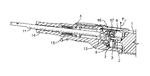
In the embodiment depicted in Figure 1 a portion of an electrically driven
device in the form of
an electric toothbrush is shown. The device comprises an electric motor 1 with
a drive shaft 2
rotating during use. As shown in the enlarged view of Figure 2, a pin 3 is
eccentrically attached
to the drive shaft 2. The motor 1 is constrained in a device housing 4 which
is only partly visible
in Figures 1 and 2. The housing 4 may be a single, unitary component part
suitable for encasing
and/or mounting further component parts of the device. In other embodiments,
the housing may
comprise different component parts, for example an outer shell, an insert, a
chassis and/or a
frame.
The pin 3 is coupled to a sliding block 5 such that the sliding block 5
follows movement of the
pin 3. However, the pin 3 may be rotated within an aperture of the sliding
block 5 which is
guided in a sliding support 6 of a cross slider 7. The cross slider 7 is
mounted in the housing 4 by
means of two bars 8 and 9. The cross slider 7 comprises a link 10 in the form
of a bearing cup for
coupling the cross slider 7 to a driven shaft 11. The sliding block 5 and the
cross slider 7
constitute a first transmission stage of a gear mechanism.
CA 03034787 2019-02-22
WO 2018/060790 PCT/IB2017/055331
9
The link 10 receives a pin 12 as a counter link which is connected to the
driven shaft 11 by
means of a yoke spring 13. The design of the yoke spring 13 is shown for
example in Figures 1,
4, 5a and 5b. The yoke spring 13 is rigidly attached to the driven shaft 11
preventing relative
rotational and axial movement of the yoke spring 13 with respect to the driven
shaft 11. In the
embodiment depicted in the Figures, the yoke spring 13 comprises two bows
extending from the
driven shaft 11 which are both fixed to the pin 12. Thus, the pin 12 may be
elastically displaced
with respect to the driven shaft 11 in the radial direction of the driven
shaft 11, i.e. the distance
between the pin 12 and the driven shaft 11 may be varied against the elastic
force of the yoke
spring 13. The yoke spring 13 constitutes a second transmission stage of the
gear mechanism.
The driven shaft 11 is rotatably guided in a rocker frame 14 which is
pivotably mounted in the
housing 4 by means of a bar 15. Pivoting of the rocker frame 14 about bar 15
with respect to the
housing 4 is compensated by the yoke spring 13. A leaf spring 16 is arranged
interposed between
of the housing 4 and the rocker frame 14. A further bar 17 is constrained in
the housing 4 at a
position abutting or in close contact with the driven shaft 11 at the end of
the driven shaft 11
facing towards the motor 1.
The rocker frame 14 is provided with an indicator 18 (cf. Figures 2 and 6)
which may be
provided with a magnet. The position of the magnet, i.e. the displacement of
the rocker frame,
may be detected by means of a hall sensor (not shown). As an alternative, the
indicator may
activate a switch, an optical detector or an inductive proximity sensor.
As can be seen in Figure 1, the drive shaft 2 of the motor 1 defines the first
rotary axis I. In the
position of the rocker frame 14 as shown in Figure 2 a second rotary axis II
defined by the driven
shaft 11 extends in parallel to the first rotary axis I. A third axis III is
defined by the sliding
support 6 within the cross slider 7. The third axis III is perpendicular to
the first rotary axis I. A
fourth axis IV is defined by bar 8 and is parallel to bars 5 and 17. The
fourth axis IV is
perpendicular to the first rotary axis I and perpendicular to the third axis
III.
In the following, operation of the device is explained in more detail with
reference to Figures 2,
3a, 3b, 5a, 5b, 7a and 7b. Figures 3a and 3b depict different positions of the
sliding block 5 and
the cross slider 7 during operation of the motor 1. Figures 2 and 3a shows a
first position of the
drive shaft 2 and its eccentric pin 3. In this first position, sliding block 5
is located near bar 9
within sliding support 6. Further, cross slider 7 is in a center position with
the third axis III of the
CA 03034787 2019-02-22
WO 2018/060790 PCT/1B2017/055331
sliding support 6 crossing the first rotary axis I. In Figure 3b motor 1
rotated drive shaft 2 by 90'
as indicated by an arrow depicting the movement of pin 3. By this rotation of
pin 3 about the first
rotary axis I, sliding block 5 is displaced within sliding support 6 away from
bar 9. In addition,
cross slider 7 is displaced to the left as seen in Figure 3b. Summarizing,
rotation of motor 1
5 causes an oscillating sinusoidal side to side motion of cross slider 7 by
means of the first
transmission stage.
This oscillating side to side motion of cross slider 7 causes an oscillating
pivoting of driven shaft
11 by means of the second transmission stage. This is depicted in Figures 5a
and 5b, wherein
10 Figure 5a corresponds to the position of the motor 1 shown in Figure 3a and
Figure 5b
corresponds to the position of the motor 1 shown in Figure 3b. Due to the
offset of pin 12 with
respect to driven shaft lithe side to side motion of cross slider 7 causes the
driven shaft 11 to
rotate about the second rotary axis II. This can be seen comparing Figures 5a
and 5b, wherein
lateral displacement of the link 10 of the cross slider 7 results in a rotary
motion of the driven
shaft 11 due to the coupling of the link 10 and the counter link 12 and the
yoke spring 13.
The angular velocity of the driven shaft 11 has a maximum at 0 and 180 of
the rotation of the
drive pin 3. This angular velocity may even exceed the angular velocity of a
pure sinusoidal
movement. Especially, the velocity of driven shaft 11 in a range between about
30 prior and
after a middle position is increased which may have benefits resulting e.g.
from a higher speed of
bristles of a toothbrush. This may cause a better cleaning result and a better
sensation of the
bristles for a user. The second derivative of the angle of rotation psi of the
driven shaft 11 over
time is the angular acceleration. The angular acceleration of the driven shaft
11 of the present
device has improved values compared with conventional devices and compared
with a pure
sinusoidal movement, too. Especially the maximum of the angular acceleration
may be reduced,
e.g. to 2.436 rad/sec2, which is about 10% below the value for a pure
sinusoidal movement. This
results in lower inertia forces and a smoother and quieter movement of the
driven shaft 11.
In addition, lateral displacement of the link 10 of the cross slider 7 results
in a force Fx acting on
the driven shaft 11 and the rocker frame 14. For example, the biasing force
FAi of the spring is
larger than the force Fx generated during rotation of motor 1. In other words,
the rocker frame 14
is held in abutment with the first stop 8 if no external force is exerted on
the driven shaft 11. That
is, the rocker frame 14 is held in its zero position shown in Figure 2.
However, if a user exerts a
force in the magnitude between the lower threshold and the upper threshold on
the driven shaft
CA 03034787 2019-02-22
WO 2018/060790 PCT/IB2017/055331
11
11, for example a contact pressure during use of a toothbrush, the rocker
frame 14 is allowed to
float between the first stop 8 and the second stop 17. During this floating
state or position, the
force Fx acting on the driven shaft 11 causes a pulsating swiveling motion of
the driven shaft 11
resulting in a 3D motion of the driven shaft 11.
The working principle of generating such a 3D motion of the driven shaft 11 is
depicted in Figure
8, too. In this schematic example leaf spring 16 is replaced by a coil spring
16' and yoke spring
13 is replaced by a further coil spring 13'. As can be seen in Figure 8, a
pulsating force Fx acting
on the driven shaft 11 and the rocker frame 14 results in a pulsating
swiveling motion of the
driven shaft 11 only if a force applied by a user (indicated by an arrow in
Figure 8) exceeds an
lower threshold allowing the rocker frame 14 to lose contact with the first
stop 8' and is below an
upper threshold such that the rocker frame 14 does not contact the second stop
17'.
Taking into account that the value of the pulsating force Fx acting on the
driven shaft 11 and the
rocker frame 14 varies during rotation of motor 1, swiveling of the rocker
frame 14 may occur
with a small amplitude if the force exerted by the user is near the lower
threshold, i.e. the rocker
frame 14 loses contact with the first stop only at or near the peak of Fx but
remains in abutment
with the first stop if the force Fx is near the value zero. In a similar way
the amplitude of the
swiveling motion of the rocker frame 14 is reduced if the force exerted by the
user is near the
upper threshold, i.e. the rocker frame 14 comes in abutment with the second
stop at or near the
peak of Fx hut remains in floating hetween the first stop and the second stop
if the force Fx is
near the value zero. This may be used to provide a feedback to the user
whether or not the contact
pressure applied by the user is within an intended or a desired range.
Figure 9 shows an example of the design of leaf spring 16. The leaf spring 16
has a generally
rectangular shape with a fork-like configuration at one end for attachment of
the leaf spring 16
with the rocker frame 14. The leaf spring 16 further comprises two lateral
latches extending from
the mainly rectangular plate with an angle of about 80 to 95 . The lateral
latches increase the
stiffness of leaf spring 16 such that the spring stiffness is mainly defined
by the flat end of the
leaf spring 16 which is not provided with latches and faces away from the fork-
like end. This
configuration of the leaf spring 16 has the benefit that the leaf spring may
be mounted into the
device by inserting after further component parts of the device have been
assembled.
CA 03034787 2019-02-22
WO 2018/060790 PCT/1B2017/055331
12
Figure 10 shows an alternative arrangement of the drive pin 3 with respect to
the drive shaft 2 of
the motor 1. In this embodiment a further gear mechanism is interposed between
the drive shaft 2
and the drive pin 3. In more detail, a pinion 19 is provided on the drive
shaft 2 meshing with a
ring gear 20 which in turn carries the drive pin 3. The gear ratio between the
drive shaft 2 and the
.. drive pin 3 may be adapted as required, e.g. depending from the torque
and/or voltage of the
motor 1.
The dimensions and values disclosed herein are not to be understood as being
strictly limited to
the exact numerical values recited. Instead, unless otherwise specified, each
such dimension is
intended to mean both the recited value and a functionally equivalent range
surrounding that
value. For example, a dimension disclosed as "40 mm" is intended to mean
"about 40 mm."
CA 03034787 2019-02-22
WO 2018/060790
PCT/1B2017/055331
13
Reference Numerals
1 motor
2 drive shaft
3 pin
4 housing
sliding block
6 sliding support
7 cross slider
8, 8' bar (first stop)
9 bar
link
11 driven shaft
12 pin (counter link)
13, 13' spring
14 rocker frame
bar
16, 16' spring
17, 17' bar (second stop)
18 indicator
19 pinion
ring gear
first rotary axis
II second rotary axis
III third axis
IV fourth axis