Note : Les descriptions sont présentées dans la langue officielle dans laquelle elles ont été soumises.
- 1 -
COMPOSITE PIPE ASSEMBLY
TECHNICAL FIELD
The present disclosure relates to composite pipe assemblies, in particular,
but not
exclusively to pipes such as fuel pipes used in aircraft or the like and
having a
composite fibre structure.
BACKGROUND
Composite pipes e.g. comprising glass or carbon fibre composite materials have
become common in applications where the pipes may be subjected to extreme
loads and conditions such as in aircraft. Aircraft fuel pipes, for example,
are often
composite pipes. Such composites are strong and stiff and less liable to
breakage
or fracture than conventionally used heavy metals whilst also being lighter.
In
extreme conditions, the composite pipes need to be resistant to damage due to
the
mechanical and environmental conditions. Further, the structures have to be
adapted to withstand misuse such as having a heavy load applied thereto or to
material damage caused by impact. At the same time, manufacturers are under
pressure to provide parts at lower cost and to provide lighter parts.
Safety is, of course, paramount for aircraft parts. It is vital to known when
a part,
such as a fuel pipe is damaged so that it can be immediately repaired and/or
replaced. Damage which goes unnoticed but which could result in failure of a
part,
can have catastrophic consequences. The ability to promptly detect damage to
the
material or structure of a component, even if that damage is not immediately
visible,
is critically important.
Impact damage is one of the most commons forms of damage to composite fibre
aircraft parts. Impact damage can occur during assembly, installation,
maintenance
or ordinary use. The components can themselves be dropped or heavy objects
such as tools can fall on them or can collide with them. Often, after impact,
no
damage, or at least no significant damage, is visible at the surface of the
component, but it may be that the impact has caused significant damage to the
inner layers of the composite structure.
CA 3040493 2019-04-16
- 2 -
Barely visible impact damage (BVID) is damage, due to impact, that can only
just
be seen with the naked eye on a very close inspection. Airlines have strict
requirements as to how BVID must be detected or monitored. This is usually
achieved by providing additional layers of composite fibres in the component.
This,
however, adds considerably to the size, weight and cost of the component.
DE 20 2015 006 737 describes providing a coating on a pipe to indicate damage.
Figs. la and lb show cross-sectional schematic views of conventional composite
pipes such as fuel pipes. Fig. 1 a is an external pipe with a pipe body 1.
This is
typically a single structural layer and can be provided with different
finishes
including textured, machined or painted. The ends of the pipe body are
provided
with grooves 2 to receive 0-ring seals 3. End fittings 4,5 are mounted into
the ends
of the pipe body 1 and are sealingly held in place by the seals 3. The end
fittings
are usually made of metal e.g. aluminium, titanium or steel, but can also be
made of
composite materials.
Fig. lb is an internal pipe which is similar in structure to the external pipe
of Fig. 1 a
except that the fittings 4', 5' are mounted to the outside of the ends of the
pipe body
1' via 0-ring seals 3' mounted in grooves 2' formed in the outer surface of
the pipe
body. The seals may typically be made of elastomeric material or nitrile or
silicone
rubber.
Visual inspections are essential in all aerospace, and many other
applications.
To avoid or detect impact damage, some conventional pipes comprise a pipe body
with a dual or multiple layer structure but this adds to the size and weight
of the
pipe. In other solutions, different textures or ribs may be provided on the
outer
surface of the pipe body which will provide visual evidence of impact damage.
There is a need for a composite component wherein impact damage can be more
easily and quickly detected without significantly adding to the size, weight
or cost of
the pipe.
SUMMARY
CA 3040493 2019-04-16
- 3 -
According to the present disclosure, there is provided a pipe assembly
comprising a
composite pipe, and end connector provided at an end of the pipe, and means
for
providing a visual indication of impact damage to the pipe, the means for
providing
a visual indication of impact damage to the pipe comprising a thin sleeve
mounted
around, but spaced from, a pipe body of the composite pipe, whereby at each
end
of the pipe body, the pipe body, the sleeve and the end connector are fitted
together, and wherein the sleeve is configured to provide a visual indication
indicative of an impact acting on the sleeve even if the impact does not reach
the
pipe body.
The sleeve may be a sleeve of thin, brittle material that exhibits visible
cracks
indicative of the impact. Alternatively, the sleeve may be in the form of a
bellows or
concertina sleeve or in the form of a transparent sleeve containing a liquid
that
changes e.g. colour on impact. Other sleeves configured to show an effect of
impact are also envisaged.
The sleeve may be mounted around the pipe with the end connector within the
sleeve or with the end connector outside the sleeve.
BRIEF DESCRIPTION OF THE DRAWINGS
Fig. 1 a is a schematic cross-sectional view of a conventional pipe with
internally
fitted end connectors.
Fig. lb is a schematic cross-sectional view of a conventional pipe with
externally
fitted end connectors.
Fig. 2 is a perspective view of a pipe assembly according to the disclosure.
Figs. 3 to 10 are partial cross sectional views of an end of different
embodiments of
pipes according to the disclosure.
CA 3040493 2019-04-16
- 4 -
DETAILED DESCRIPTION
According to the present disclosure, improved impact damage detection is
provided
by providing a relatively thin sleeve around, but spaced from, the pipe body
of a
composite pipe, whereby at each end of the pipe body, the pipe body, the
sleeve
and an end connector are sealingly fitted together, and wherein the sleeve is
configured to provide a visual indication indicative of an impact that has
acted on
the sleeve even if the impact did not reach the pipe body.
The relatively thin sleeve is fitted around the pipe body, at a distance
therefrom, so
that it immediately shows the effect of an impact against the sleeve.
The sleeve can take different forms and can provide the visual indication of
the
impact in different ways, but in all embodiments, the thickness of the sleeve
should
be less that the additional thickness that would be required for a
conventional multi-
layered pipe and there should be a space or gap between the impact-taking
sleeve
and the pipe body, e.g. 50mm OD, 2mm wall, 5mm gap (to allow deflection). This
allows the outer sleeve to be damaged by the impact and to show that damage
before the inner pipe is affected by the impact. The gap can also provide some
protection to the inner pipe.
The sleeve can be applied to pipes where the end fittings are internal to the
pipe
body (as in Fig. la) or external (as in Fig. 1b).
This disclosure concerns providing an indication of impact damage to a
composite
tube or pipe. Such pipes are known in many fields and these are generally
glass
fibre or carbon fibre composite pipes (or combinations thereof). The outer
body is
usually a conductive carbon-rich gel coat to optimise electrical flow to
ground/earth.
An impact indicating sleeve is provided on the tube, according to the
disclosure, as
described further below.
Fig. 2 shows a perspective view of an example of the pipe assembly where the
sleeve is a thin brittle sleeve 20 about the pipe body 10. In the event of an
impact
against the pipe, it would first cause the brittle outer sleeve to visibly
crack 30 over
CA 3040493 2019-04-16
- 5 -
a large part of its surface, even before the impact has damaged the inner pipe
body. The crack 30 provides a clear indication that the pipe assembly should
be
further inspected for damage and/or removed and replaced or repaired.
In addition to providing an immediate visual indication that impact has
occurred
(which might have damaged the interior layers of the composite pipe), the
sleeve,
spaced from the pipe, takes the impact first, before the pipe, potentially
providing a
protective function.
Various ways of implementing the sleeve are shown in Figs. 3 to 10. These are
examples only and are not limiting to the scope of the disclosure. All of the
examples can be adapted to internal or external pipes.
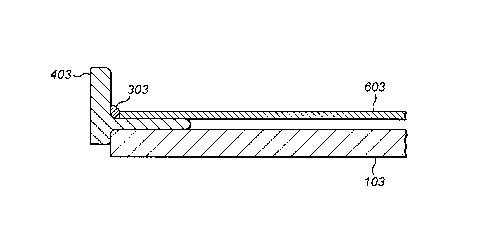
Fig. 3 shows the pipe body 103 to which an end fitting 403 is mounted, similar
to
the conventional fitting of Fig. lb. A thin, brittle BVID layer 603 is mounted
around
the pipe body and sealed e.g. by elastomeric supports 303 to the pipe body and
the
end connector at the ends (only one end is shown). As shown in Fig. 2, if an
impact
acts on the pipe, it will impact the sleeve 603 first. This is made of a thin
brittle
material e.g. Polystyrene, polymethyl methacrylate (Acrylic) or another
polymer,
selected to crack in a large spread out crack 30 on impact that can quickly
and
easily be seen and even before the impact affects the pipe body 103.
Fig. 4 is similar to Fig. 3, but the pipe body 104 is external to the fitting
404 (similar
to Fig. la). At the end, the pipe body is sealed with the end fitting by a
sealant 304.
The sleeve of thin brittle material 604 is sealed to the pipe body by another
seal
704.
Fig. 5 is similar to Fig. 3 and Fig. 4 except here the end fitting 405 does
not extend
into or around the pipe body 105. Instead the pipe body 105 and sleeve 605 are
secured to the end fitting by a seal 905.
Fig. 6 is again a similar embodiment except that the way the end fitting 406
is
sealed to the pipe body 106 and sleeve 606 is different, as shown.
CA 3040493 2019-04-16
- 6 -
In Fig. 7, the end fitting is in the form of a mount or connector 807 for
attachment to
another component and the pipe body 107 and sleeve 607 are attached
mechanically. The sleeve and the pipe body could be attached in various ways
e.g.
by adhesive, by a bonded seal, by interference fit etc.
Figs. 8a and 8b show a different means for providing a visual indication of
the
impact ¨ here the sleeve is a transparent sleeve 608 around the pipe body 108
and
a liquid is provided in the gap between the pipe body and the sleeve. The
liquid 908
is selected to be a liquid that changes some characteristic on application of
force or
impact for example changes colour. When the sleeve 608 experiences an impact,
this is transferred to the liquid 908 causing it to change colour, which can
be seen
through the transparent sleeve 608, or, the change in fluid characteristic can
be that
it expands or changes temperature and this may cause the sleeve to break (fig.
8b,
1008). An alternative (not shown) is to use pressure sensitive or pH sensitive
paper
that changes colour on impact.
In the embodiment of Fig. 9A, the sleeve has a folded, concertina or bellows
form
609 around the pipe body 109 and this distorts on impact.
In Fig. 9B, the sleeve is in the form of a "partial" bellows 609'. Fuel
leakage from
the inner tube would be visible, e.g. air bubbles.
In the embodiment of Fig. 10 the sleeve 610 is in the form of a double walled
sleeve
defining cavities 910 separated by thin walls 1010. On impact, the sleeve
deforms
and the cavities deform. Deformation from a regular shape is an indication of
impact. A slight deformation might be indicated by e.g. a white 'stretch mark'
in the
sleeve material.
The end fittings for all embodiments can be readily available fittings or can
be easily
adapted to receive both the pipe body and the sleeve.
The light, thin, brittle sleeve or sleeve whose visible characteristics change
on
impact allows for improved, more reliable BVID inspection and weight saving
compared to conventional techniques, as well as reduced material costs.
CA 3040493 2019-04-16
- 7 -
Whilst described in relation to aircraft components such as fuel pipes, there
are
other composite components for which BVID can be monitored using the assembly
of the disclosure.
CA 3040493 2019-04-16