Sélection de la langue

Search

Sommaire du brevet 3043826 

Énoncé de désistement de responsabilité concernant l'information provenant de tiers

Une partie des informations de ce site Web a été fournie par des sources externes. Le gouvernement du Canada n'assume aucune responsabilité concernant la précision, l'actualité ou la fiabilité des informations fournies par les sources externes. Les utilisateurs qui désirent employer cette information devraient consulter directement la source des informations. Le contenu fourni par les sources externes n'est pas assujetti aux exigences sur les langues officielles, la protection des renseignements personnels et l'accessibilité.

Disponibilité de l'Abrégé et des Revendications

L'apparition de différences dans le texte et l'image des Revendications et de l'Abrégé dépend du moment auquel le document est publié. Les textes des Revendications et de l'Abrégé sont affichés :

  • lorsque la demande peut être examinée par le public;
  • lorsque le brevet est émis (délivrance).
(12) Demande de brevet: (11) CA 3043826
(54) Titre français: SYSTEME D`EXCAVATION HYDRAULIQUE AVEC DETECTION D`OBJETS
(54) Titre anglais: HYDROVAC EXCAVATION SYSTEM HAVING OBJECT DETECTION
Statut: Examen
Données bibliographiques
(51) Classification internationale des brevets (CIB):
  • E21C 25/60 (2006.01)
  • E02B 1/00 (2006.01)
  • E02F 3/88 (2006.01)
  • E02F 5/16 (2006.01)
(72) Inventeurs :
  • AUCLAIR, WILLIAM (Canada)
(73) Titulaires :
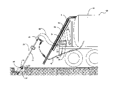
  • WILLIAM AUCLAIR
(71) Demandeurs :
  • WILLIAM AUCLAIR (Canada)
(74) Agent: RICHARD D. OKIMAWOKIMAW, RICHARD D.
(74) Co-agent:
(45) Délivré:
(22) Date de dépôt: 2019-05-21
(41) Mise à la disponibilité du public: 2020-11-17
Requête d'examen: 2024-04-22
Licence disponible: S.O.
Cédé au domaine public: S.O.
(25) Langue des documents déposés: Anglais

Traité de coopération en matière de brevets (PCT): Non

(30) Données de priorité de la demande:
Numéro de la demande Pays / territoire Date
18415842 (Etats-Unis d'Amérique) 2019-05-17

Abrégés

Abrégé anglais


An excavation system that is configured to utilize water pressure and
vacuum to provide removal of terrain from an area wherein the excavation
system
is further configured to provide detection and alert of subterranean objects
in the
excavation area. The excavation system includes a digging wand that is
operably
coupled to a water source. The digging wand includes a plurality of water jets
that
are configured to emit water. The digging wand further includes in the nozzle
thereof a plurality of detection transceivers. The detection transceivers are
configured to provide detection of subterranean objects proximate the nozzle
of the
digging wand during the excavation process. The controller of the present
invention
includes a screen that provides image data of the area proximate the nozzle.
The
controller further provides at least two operational modes wherein one of the
operational modes provides reduction of water pressure upon detection of a
subterranean object.

Revendications

Note : Les revendications sont présentées dans la langue officielle dans laquelle elles ont été soumises.


WHAT IS CLAIMED IS:
1. An excavation system that is operable to provide excavation of an area and
further provide detection of subterranean objects wherein the excavation
system
comprises:
a digging wand, said digging wand having a first end and a second end, said
digging wand being constructed of tubular metal, said digging wand having a
nozzle
operably coupled thereto at said second end thereof, said nozzle having at
least one
water jet configured to have water egress therefrom;
a controller, said controller having the necessary electronics to store,
transmit, receive and manipulate data, said controller being operably coupled
to
said digging wand;
at least one detection transceiver, said at least one detection transceiver
being disposed within said nozzle, said at least one detection transceiver
configured
to provide detection of subterranean objects proximate said nozzle during
excavation of an area.
2. The excavation system as recited in claim 1, wherein said at least one
detection
transceiver is configured to utilize an imaging technique selected from one of
the
following: magnetic, ultrasound or x-ray.
3. The excavation system as recited in claim 2, wherein said controller is
configured
to provide a first operational mode and a second operational mode of the
excavation
system.
4. The excavation system as recited in claim 3, wherein said controller is
further
configured with a screen, said screen providing visual image of an area
proximate to
said nozzle during excavation.
5. The excavation system as recited in claim 4, and further including a
control
interface, said control interface operably coupled to said digging wand on
said first

end thereof, said control interface providing operably coupling of said
digging wand
to said controller.
6. The excavation system as recited in claim 5, and further including a visual
alarm,
said visual alarm operable to provide a visual indicator of detection of a
subterranean object proximate said nozzle.
7. The excavation system as recited in claim 6, wherein in said second mode of
operation of the excavation system said controller is configured to reduce
water
pressure egressing from the at least one water jet subsequent detection of a
subterranean object being proximate said nozzle.
8. An excavation system that is configured to utilize a combination of
pressurized
water and vacuum to provide excavation of an area wherein the excavation
system
comprises:
a storage tank, said storage tank having a vacuum hose operably coupled
thereto, said storage tank having an interior volume configured to receive and
store
excavated material and water;
a digging wand, said digging wand having a first end and a second end, said
digging wand being constructed of tubular metal, said digging wand having a
nozzle
operably coupled thereto at said second end thereof, said nozzle having an
interior
volume;
a plurality of water jets, said plurality of water jets being disposed within
the
interior volume of said nozzle, said plurality of water jets fluidly coupled
to said
storage tank;
a controller, said controller having the necessary electronics to store,
transmit, receive and manipulate data, said controller being operably coupled
to
said digging wand; and
a plurality of detection transceivers, said plurality of detection
transceivers
being disposed within the interior volume of said nozzle, said plurality of
detection
11

transceivers configured to provide detection of subterranean objects proximate
said
nozzle during excavation of an area.
9. The excavation system as recited in claim 8, wherein the excavation system
includes a first operational mode and a second operational mode wherein in the
first
operational mode water pressure egressing from the plurality of water jets is
constant.
10. The excavation system as recited in claim 9, wherein said controller
further
includes a screen, said screen being operable to provide image data of an area
proximate the digging wand during excavation.
11. The excavation system as recited in claim 10, wherein said plurality of
detection
transceivers are configured to utilize an imaging technique selected from one
of the
following: magnetic, ultrasound or x-ray.
12. The excavation system as recited in claim 11, wherein said controller
further
includes an audio and visual alarm, said audio and visual alarm operable to
provide
visual and audial warning of a subterranean object proximate said digging
wand.
13. The excavation system as recited in claim 12, wherein in said second
operational
mode of the excavation system said controller is configured to reduce water
pressure egressing from the plurality of water jets subsequent detection of a
subterranean object being proximate said nozzle.
14. The excavation system as recited in claim 13, wherein said controller
provides a
third operational mode wherein in said third operational mode the controller
provides preprogrammed water pressures for specific applications.
12

15. An excavation system that is configured to utilize a combination of
pressurized
water and vacuum to provide excavation of an area and detection of
subterranean
objects during the excavation process wherein the excavation system comprises:
a storage tank, said storage tank having a vacuum hose operably coupled
thereto, said storage tank having an interior volume configured to receive and
store
excavated material and water;
a digging wand, said digging wand having a first end and a second end, said
digging wand being constructed of tubular metal, said digging wand having a
nozzle
operably coupled thereto at said second end thereof, said nozzle having an
interior
volume;
a plurality of water jets, said plurality of water jets being disposed within
the
interior volume of said nozzle, said plurality of water jets fluidly coupled
to said
storage tank;
a controller, said controller having the necessary electronics to store,
transmit, receive and manipulate data, said controller being operably coupled
to
said digging wand;
a plurality of detection transceivers, said plurality of detection
transceivers
being disposed within the interior volume of said nozzle, said plurality of
detection
transceivers configured to provide detection of subterranean objects proximate
said
nozzle during excavation of an area; and
wherein said controller is configured to provide a first operational mode and
a second operational mode wherein in said first operational mode said
controller is
operable to provide a constant water pressure to the plurality of water jets.
16. The excavation system as recited in claim 15, wherein in said second
operational
mode of the excavation system said controller is configured to reduce water
pressure egressing from the plurality of water jets subsequent detection of a
subterranean object being proximate said nozzle.
13

17. The excavation system as recited in claim 16, wherein said plurality of
detection
transceivers are configured to utilize an imaging technique selected from one
of the
following: magnetic, ultrasound or x-ray.
18. The excavation system as recited in claim 17, wherein said controller
further
includes an audio and visual alarm, said audio alarm being a speaker
integrated into
said controller, said visual alarm being a light on said controller, said
audio and
visual alarm operable to provide visual and audial warning of a subterranean
object
proximate said digging wand.
19. The excavation system as recited in claim 18, wherein said controller
provides a
third operational mode, said third operational mode providing operational
parameters for alternate soil types, wherein in said third operational mode
the
controller provides preprogrammed water pressures for specific applications.
20. The excavation system as recited in claim 19, wherein in said second
operational
mode the controller is operable to reduce water pressure egressing from the
plurality of water jets across a pressure gradient.
14

Description

Note : Les descriptions sont présentées dans la langue officielle dans laquelle elles ont été soumises.

HYDROVAC EXCAVATION SYSTEM HAVING OBJECT DETECTION
FIELD OF THE INVENTION
[001] The present invention relates generally to excavation systems, more
specifically but not by way of limitation, an excavation system that utilizes
a
combination of high pressure water and a vacuum system to facilitate the
removal of dirt from a desired area wherein the present invention includes a
high pressure water wand that is configured to provide object detection so as
to inhibit damage thereto during the excavation process.
BACKGROUND
[002] As is known in the art, there are various techniques for excavating
areas depending upon the construction application. For general excavation,
equipment such as bulldozers and the like are utilized to provide general
leveling and removing of terrain from a desired area. For other applications
such as but not limited to pipeline excavation, it can be common to use
equipment such as backhoes or hydrovac systems. Hydrovac excavation
system are comprised of a vacuum system and a high pressure water system
wherein the combination of the two are utilized to dislodge and remove dirt
from a targeted area. The systems include a water source operably coupled
to a digging wand wherein the digging wand is used to direct a stream of high
pressure water to dislodge dirt proximate the discharge end of the digging
wand from which water is egressing therefrom. As the water is ejected from
the digging wand at high pressure, a vacuum hose is placed proximate
thereto and is operable to remove the water/dirt from the area and transfer
to either another location or temporary holding tank.
[003] While the aforementioned is effective at removal of dirt there are
deficiencies with the existing technology. The water ejected from the digging
wand is typically done at a very high water pressure that can be thousands of
1
CA 3043826 2019-05-21

pounds per square inch. When utilizing a digging wand, the operator has no
visibility to any object that may be in the area being excavated such as but
not limited to a pipeline. As an operator excavates with a digging wand it can
be a common occurrence wherein the lack of visibility in the area being
excavated results in damage to objects such as but not limited to pipeline,
fiber optic cable and other buried objects.
[004] Accordingly, there is a need for a hydrovac excavation system that is
configured to provide detection of objects proximate the digging wand and
provide an alert thereto in order to prevent damage to the detected object.
SUMMARY OF THE INVENTION
[005] It is the object of the present invention to provide a hydrovac
excavation system that is configured to provide removal of dirt in a targeted
area utilizing the combination of vacuum and high pressure water wherein
the present invention is operable to provide object detection for
subterranean objects.
[006] Another object of the present invention is to provide a hydrovac
excavation system operable to utilize high pressure water to effect removal
of dirt in a targeted area wherein the high pressure water is directed
outward from a wand.
[007] A further object of the present invention is to provide a hydrovac
excavation system that is configured to provide removal of dirt in a targeted
area utilizing the combination of vacuum and high pressure water wherein
the wand of the present invention is equipped with detection transceivers
that are configured to provide detection of subterranean objects proximate
to the end thereof.
[008] Still another object of the present invention is to provide a
hydrovac
excavation system operable to utilize high pressure water to effect removal
of dirt in a targeted area wherein the sensors are configured to utilize
2
CA 3043826 2019-05-21

ultrasound, magnetic, x-ray or alternate technology to provide detection of
subterranean objects.
[009] An additional object of the present invention is to provide a
hydrovac
excavation system that is configured to provide removal of dirt in a targeted
area utilizing the combination of vacuum and high pressure water wherein
the digging wand of the present invention is operably coupled to a controller
that will provide water pressure control thereof.
[0010] Yet a further object of the present invention is to provide a
hydrovac
excavation system operable to utilize high pressure water to effect removal
of dirt in a targeted area wherein the controller of the present invention is
operable to reduce the water pressure egressing from the digging wand
subsequent detection of a subterranean object being proximate thereto.
[0011] Another object of the present invention is to a provide a
hydrovac
excavation system that is configured to provide removal of dirt in a targeted
area utilizing the combination of vacuum and high pressure water wherein
the present invention may be utilized with or without a vacuum component.
[0012] An alternate object of the present invention is to provide a
hydrovac
excavation system operable to utilize high pressure water to effect removal
of dirt in a targeted area wherein the controller is configured with an audio
alarm to alert the operator upon detection of a subterranean object.
[0013] Still a further object of the present invention is to provide a
hydrovac
excavation system that is configured to provide removal of dirt in a targeted
area utilizing the combination of vacuum and high pressure water wherein
the controller of the present invention further includes a graphical interface
providing a visual display of the area proximate the end of the digging wand.
[0014] An additional object of the present invention is to provide a
hydrovac
excavation system operable to utilize high pressure water to effect removal
of dirt in a targeted area wherein the controller provides fixed water
pressure settings for alternate applications or terrain type.
[0015] To the accomplishment of the above and related objects the
present
invention may be embodied in the form illustrated in the accompanying
3
CA 3043826 2019-05-21

drawings. Attention is called to the fact that the drawings are illustrative
only. Variations are contemplated as being a part of the present invention,
limited only by the scope of the claims.
BRIEF DESCRIPTION OF THE DRAWINGS
[0016] A more complete understanding of the present invention may be
had
by reference to the following Detailed Description and appended claims
when taken in conjunction with the accompanying Drawings wherein:
[0017] Figure 1 is a perspective view of an exemplary embodiment of
the
present invention.
DETAILED DESCRIPTION
[0018] Referring now to the drawings submitted herewith, wherein
various
elements depicted therein are not necessarily drawn to scale and wherein
through the views and figures like elements are referenced with identical
reference numerals, there is illustrated an excavation system 100
constructed according to the principles of the present invention.
[0019] An embodiment of the present invention is discussed herein with
reference to the figures submitted herewith. Those skilled in the art will
understand that the detailed description herein with respect to these figures
is for explanatory purposes and that it is contemplated within the scope of
the present invention that alternative embodiments are plausible. By way of
example but not by way of limitation, those having skill in the art in light
of
the present teachings of the present invention will recognize a plurality of
alternate and suitable approaches dependent upon the needs of the
particular application to implement the functionality of any given detail
described herein, beyond that of the particular implementation choices in the
embodiment described herein. Various modifications and embodiments are
within the scope of the present invention.
4
CA 3043826 2019-05-21

[0020] It is to be further understood that the present invention is
not limited
to the particular methodology, materials, uses and applications described
herein, as these may vary. Furthermore, it is also to be understood that the
terminology used herein is used for the purpose of describing particular
embodiments only, and is not intended to limit the scope of the present
invention. It must be noted that as used herein and in the claims, the
singular
forms "a", "an" and "the" include the plural reference unless the context
clearly dictates otherwise. Thus, for example, a reference to "an element" is
a
reference to one or more elements and includes equivalents thereof known
to those skilled in the art. All conjunctions used are to be understood in the
most inclusive sense possible. Thus, the word "or" should be understood as
having the definition of a logical "or" rather than that of a logical
"exclusive
or" unless the context clearly necessitates otherwise. Structures described
herein are to be understood also to refer to functional equivalents of such
structures. Language that may be construed to express approximation should
be so understood unless the context clearly dictates otherwise.
[0021] References to "one embodiment", "an embodiment", "exemplary
embodiments", and the like may indicate that the embodiment(s) of the
invention so described may include a particular feature, structure or
characteristic, but not every embodiment necessarily includes the particular
feature, structure or characteristic.
[0022] Now referring in particular to the Figures submitted herewith,
the
excavation system 100 includes a storage tank 10. The storage tank 10 herein
is illustrated for exemplary purposes and it is contemplated within the scope
of the present invention that the storage tank 10 could be configured in
various alternative embodiments and sizes. Furthermore, it is contemplated
within the scope of the present invention that the storage tank 10 could
include a first portion and a second portion wherein the first portion is
configured to store water and the second portion is configured to receive the
materials being excavated. It should be also understood within the scope of
the present invention that the excavation system 100 could be implemented
CA 3043826 2019-05-21

either with or without vacuum capabilities. Additionally, it is contemplated
within the scope of the present invention that the excavation system 100
could be operably coupled to a water supply instead of utilizing stored water.
The storage tank 10 has a vacuum hose 5 operably coupled thereto and is
operably coupled to a conventional vacuum motor(not illustrated herein)
wherein the vacuum hose 5 is manipulated to be placed proximate the
digging wand 20 and retrieve the material dislodged by the digging wand 20
and transfer to at least one portion of the storage tank 10.
[0023] Operably coupled to the storage tank 10 and in particular a
fluid
disposed therein, is digging wand 20. Digging wand 20 is fluidly coupled to
storage tank 10 utilizing hose 15. Hose 15 is a conventional industrial rubber
hose and it is contemplated within the scope of the present invention that the
hose 15 could be manufactured in alternate lengths and diameters. The
digging wand 20 includes base portion 22, control interface 24 and nozzle 26.
Base portion 22 is manufactured from rigid tubing such as but not limited to
metal tubing and can be provided in alternate lengths and diameters. The
control interface 24 is operably coupled to the base portion 22 utilizing
suitable mechanical techniques. The control interface 24 is operably coupled
to controller 50 and provides remote adjustment of at least some of the
functions of the excavation system 100. The control interface 24 includes
housing 25 that is configured to have disposed therein the necessary
electronics to store, receive, transmit and manipulate data. The control
interface 24 is coupled to controller 50 utilizing wires 28 wherein the wires
are conventional configuration suitable for electronic signal and data
transmission.
[0024] Distal to control interface 24 on the base portion 22 is the
nozzle 26.
The nozzle 26 is secured to the base portion 22 utilizing suitable durable
techniques. While the nozzle 26 is illustrated herein having a particular
shape, it should be understood within the scope of the present invention that
the nozzle 26 could be provide in alternate shapes and sizes. The nozzle 26
includes body 32 manufactured from a durable rigid material such as but not
6
CA 3043826 2019-05-21

limited to metal. The body 32 forms interior volume 33 being of sufficient
size to have disposed therein a plurality of water jets 36 and detection
transceivers 40. It should be understood within the scope of the present
invention that the nozzle 26 could be configured to have as few as one water
jet 36 and one detection transceiver 40 or more than one of each. The water
jet 36 is a conventional high-pressure water jet that is operable to direct a
stream of high pressure water for excavation of dirt.
[0025] The detection transceivers 40 are configured to provide
electronic
emission and receive a signal back from a detected subterranean object. The
detection transceivers 40 are operably coupled to the controller 50 as further
discussed herein and are configured to provide information to a user of the
excavation system 100 concerning the presence of subterranean objects. It is
contemplated within the scope of the present invention that the detection
transceivers 40 could be configured to employ magnetic waves, ultrasound
or x-ray to provide detection of any subterranean objects proximate the
nozzle 26. The detection transceivers 40 are operably coupled to the
controller 50 wherein the controller 50 includes screen 52 that is operable to
display images of the detected subterranean objects and provide estimates
on the distance intermediate the nozzle 26 and the subterranean object. The
detection transceivers 40 are operably coupled to the controller utilizing
suitable techniques and the controller 50 as is further discussed herein
provides operational mode control of the digging wand 20.
[0026] The controller 50 includes weatherproof housing 51 that is
configured
to create an interior volume suitable to have disposed therein the necessary
electronics to store, receive, transmit and manipulate data. The controller 50
provides operational control of the digging wand 20 of the excavation system
100 wherein a plurality of control switches 56 are present so as to facilitate
engagement of the excavation system 100. The controller 50 is configured to
provide at least a first mode and a second mode of operation of the
excavation system 100. In a first operational mode, the excavation system
100 is configured to have water egress from water jets 36 at a constant
7
CA 3043826 2019-05-21

pressure. Furthermore, in the first operational mode the detection
transceivers 40 are activated and consistently providing image feedback on
the screen 52 of the area proximate the nozzle 26 in order to identify the
presence of any subterranean objects.
[0027] In the second operational mode of the excavation system 100,
the
controller 50 is operable to reduce the water pressure egressing from the
water jets 36 ensuing detection of a subterranean object proximate the
nozzle 26. In particular, once an object is detected, a visual alarm will be
provided to a user via warning light 60 and further an audio alarm will be
provided utilizing a speaker(not illustrated herein) integrated into the
controller. The visual alarm and audio alarm provides notification to a user
that a subterranean object has been detected and the water pressure
egressing from the water jets 36 will be either reduced or potentially halted.
It is contemplated within the scope of the present invention that the second
mode of operation could vary from progressive water pressure reduction to
elimination of water pressure until reactivated by an operator of the
excavation system 100.
[0028] The controller 50 further provides operational adjustments for
applications wherein a preprogrammed water pressure is provided upon
selection of an application type utilizing switches 56. It is contemplated
within the scope of the present invention that the controller 50 could provide
alternate modes for applications wherein the applications are determined by
parameters such as but not limited to terrain type and potential
subterranean objects. It should also be understood within the scope of the
present invention that the water jets 36 could be configured to spray water
in a variety of patterns. It is contemplated within the scope of the present
invention that the controller 50 could be located on the digging wand 26, the
exemplary truck 99 or any other suitable location.
[0029] In the preceding detailed description, reference has been made
to the
accompanying drawings that form a part hereof, and in which are shown by
way of illustration specific embodiments in which the invention may be
8
CA 3043826 2019-05-21

practiced. These embodiments, and certain variants thereof, have been
described in sufficient detail to enable those skilled in the art to practice
the
invention. It is to be understood that other suitable embodiments may be
utilized and that logical changes may be made without departing from the
spirit or scope of the invention. The description may omit certain
information known to those skilled in the art. The preceding description is,
therefore, not intended to be limited to the specific forms set forth herein,
but on the contrary, it is intended to cover such alternatives, modifications,
and equivalents, as can be reasonably included within the spirit and scope of
the invention.
9
CA 3043826 2019-05-21

Dessin représentatif
Une figure unique qui représente un dessin illustrant l'invention.
États administratifs

2024-08-01 : Dans le cadre de la transition vers les Brevets de nouvelle génération (BNG), la base de données sur les brevets canadiens (BDBC) contient désormais un Historique d'événement plus détaillé, qui reproduit le Journal des événements de notre nouvelle solution interne.

Veuillez noter que les événements débutant par « Inactive : » se réfèrent à des événements qui ne sont plus utilisés dans notre nouvelle solution interne.

Pour une meilleure compréhension de l'état de la demande ou brevet qui figure sur cette page, la rubrique Mise en garde , et les descriptions de Brevet , Historique d'événement , Taxes périodiques et Historique des paiements devraient être consultées.

Historique d'événement

Description Date
Lettre envoyée 2024-06-19
Exigences pour une requête d'examen - jugée conforme 2024-04-22
Toutes les exigences pour l'examen - jugée conforme 2024-04-22
Requête d'examen reçue 2024-04-22
Inactive : Lettre officielle 2024-03-28
Demande publiée (accessible au public) 2020-11-17
Inactive : Page couverture publiée 2020-11-16
Représentant commun nommé 2019-10-30
Inactive : CIB en 1re position 2019-06-12
Inactive : CIB attribuée 2019-06-12
Inactive : Certificat dépôt - Aucune RE (bilingue) 2019-06-07
Exigences de dépôt - jugé conforme 2019-06-07
Inactive : Demandeur supprimé 2019-06-04
Inactive : CIB attribuée 2019-05-28
Demande reçue - nationale ordinaire 2019-05-24
Déclaration du statut de petite entité jugée conforme 2019-05-21

Historique d'abandonnement

Il n'y a pas d'historique d'abandonnement

Taxes périodiques

Le dernier paiement a été reçu le 

Avis : Si le paiement en totalité n'a pas été reçu au plus tard à la date indiquée, une taxe supplémentaire peut être imposée, soit une des taxes suivantes :

  • taxe de rétablissement ;
  • taxe pour paiement en souffrance ; ou
  • taxe additionnelle pour le renversement d'une péremption réputée.

Veuillez vous référer à la page web des taxes sur les brevets de l'OPIC pour voir tous les montants actuels des taxes.

Historique des taxes

Type de taxes Anniversaire Échéance Date payée
Taxe pour le dépôt - petite 2019-05-21
TM (demande, 2e anniv.) - petite 02 2021-05-21 2021-04-09
TM (demande, 3e anniv.) - petite 03 2022-05-24 2022-04-20
TM (demande, 4e anniv.) - petite 04 2023-05-23 2023-05-18
TM (demande, 5e anniv.) - petite 05 2024-05-21 2024-04-22
Requête d'examen - petite 2024-05-21 2024-04-22
TM (demande, 6e anniv.) - petite 06 2025-05-21
Titulaires au dossier

Les titulaires actuels et antérieures au dossier sont affichés en ordre alphabétique.

Titulaires actuels au dossier
WILLIAM AUCLAIR
Titulaires antérieures au dossier
S.O.
Les propriétaires antérieurs qui ne figurent pas dans la liste des « Propriétaires au dossier » apparaîtront dans d'autres documents au dossier.
Documents

Pour visionner les fichiers sélectionnés, entrer le code reCAPTCHA :


Pour visualiser une image, cliquer sur un lien dans la colonne description du document. Pour télécharger l'image (les images), cliquer l'une ou plusieurs cases à cocher dans la première colonne et ensuite cliquer sur le bouton "Télécharger sélection en format PDF (archive Zip)" ou le bouton "Télécharger sélection (en un fichier PDF fusionné)".

Liste des documents de brevet publiés et non publiés sur la BDBC .

Si vous avez des difficultés à accéder au contenu, veuillez communiquer avec le Centre de services à la clientèle au 1-866-997-1936, ou envoyer un courriel au Centre de service à la clientèle de l'OPIC.


Description du
Document 
Date
(aaaa-mm-jj) 
Nombre de pages   Taille de l'image (Ko) 
Dessin représentatif 2020-10-28 1 25
Description 2019-05-21 9 376
Abrégé 2019-05-21 1 23
Revendications 2019-05-21 5 173
Dessins 2019-05-21 1 46
Page couverture 2020-10-28 1 58
Requête d'examen 2024-04-22 3 117
Paiement de taxe périodique 2024-04-22 1 26
Changement à la méthode de correspondance 2024-04-23 3 83
Courtoisie - Lettre du bureau 2024-03-28 2 190
Courtoisie - Réception de la requête d'examen 2024-06-19 1 414
Certificat de dépôt 2019-06-07 1 206
Paiement de taxe périodique 2022-04-20 1 26
Paiement de taxe périodique 2023-05-18 1 26