Sélection de la langue

Search

Sommaire du brevet 3061683 

Énoncé de désistement de responsabilité concernant l'information provenant de tiers

Une partie des informations de ce site Web a été fournie par des sources externes. Le gouvernement du Canada n'assume aucune responsabilité concernant la précision, l'actualité ou la fiabilité des informations fournies par les sources externes. Les utilisateurs qui désirent employer cette information devraient consulter directement la source des informations. Le contenu fourni par les sources externes n'est pas assujetti aux exigences sur les langues officielles, la protection des renseignements personnels et l'accessibilité.

Disponibilité de l'Abrégé et des Revendications

L'apparition de différences dans le texte et l'image des Revendications et de l'Abrégé dépend du moment auquel le document est publié. Les textes des Revendications et de l'Abrégé sont affichés :

  • lorsque la demande peut être examinée par le public;
  • lorsque le brevet est émis (délivrance).
(12) Demande de brevet: (11) CA 3061683
(54) Titre français: DISPOSITIF DE TRANSPORT DE RAILS SOUDES EN LONGUEUR
(54) Titre anglais: DEVICE FOR TRANSPORTING LONG WELDED RAILS
Statut: Réputée abandonnée et au-delà du délai pour le rétablissement - en attente de la réponse à l’avis de communication rejetée
Données bibliographiques
(51) Classification internationale des brevets (CIB):
  • B61D 03/16 (2006.01)
  • B61D 45/00 (2006.01)
  • E01B 29/17 (2006.01)
(72) Inventeurs :
  • DANZL, ROBERT (Autriche)
  • MAIER, MICHAEL (Allemagne)
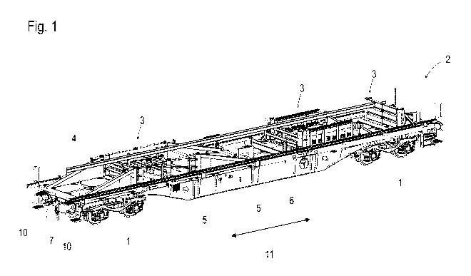
  • BRYS, HORST (Allemagne)
(73) Titulaires :
  • ROBEL BAHNBAUMASCHINEN GMBH
(71) Demandeurs :
  • ROBEL BAHNBAUMASCHINEN GMBH (Allemagne)
(74) Agent: RICHES, MCKENZIE & HERBERT LLP
(74) Co-agent:
(45) Délivré:
(86) Date de dépôt PCT: 2018-05-22
(87) Mise à la disponibilité du public: 2018-12-06
Licence disponible: S.O.
Cédé au domaine public: S.O.
(25) Langue des documents déposés: Anglais

Traité de coopération en matière de brevets (PCT): Oui
(86) Numéro de la demande PCT: PCT/EP2018/063302
(87) Numéro de publication internationale PCT: EP2018063302
(85) Entrée nationale: 2019-10-28

(30) Données de priorité de la demande:
Numéro de la demande Pays / territoire Date
20 2017 002 816.6 (Allemagne) 2017-05-29

Abrégés

Abrégé français

L'invention concerne un dispositif (3) destiné au transport de rails (4) soudés en longueur au moyen d'un train de chargement de rails, ledit dispositif comprenant un système (8) permettant de loger les rails (4) de manière fiable. A cet effet, ledit dispositif (3) se présente sous forme d'unité modulaire dotée de moyens de fixation (5) à ancrer sur un wagon à fond plat porte-conteneurs (2) et comprend sa propre unité d'alimentation en énergie (9).


Abrégé anglais


A device (3) for the transport of long-welded rails (4) by means of a rail
loading train,
including an installation (8) for secured storage of the rails (4). In this,
it is provided
that the device (3) is designed as a modular unit having fastening means (5)
for
anchoring on a container flat wagon (2) and comprises a separate energy supply
unit (9).

Revendications

Note : Les revendications sont présentées dans la langue officielle dans laquelle elles ont été soumises.


6
Claims
1. A device for the transport of long-welded rails (4) by means of a rail
loading
train, including an installation (8) for secured storage of the rails (4),
characterized in
that the device is designed as a modular unit (3) having fastening means (5)
for
anchoring on a container flat wagon (2) and comprises a separate energy supply
unit (9).
2. A device according to claim 1, characterized in that the fastening means
(5) are
arranged on a module frame (7), and that the installation (8) for guiding
and/or
locking the rails (4) is fastened to the module frame (7).
3. A device according to claim 1 or 2, characterized in that the energy
supply unit
(9) comprises a hydraulic unit, and that the installation comprises hydraulic
drives
(20).
4. A device according to one of claims 1 to 3, characterized in that the
energy
supply unit (9) comprises a combustion engine and a tank container.
5. A device according to one of claims 1 to 4, characterized in that the
energy
supply unit (9) comprises an electric machine and an electric energy store.
6. A device according to one of claims 1 to 5, characterized in that a
sleeve (27),
designed to be pushed onto a container mandrel (24) of the container flat
wagon (2),
is arranged as fastening means (5).
7. A device according to one of claims 1 to 6, characterized in that a
clamping
device (28) is arranged as fastening means (5) which is designed to be pushed
onto
a socket (25) for a container mandrel (24) provided on the container flat
wagon (2).
8. A device according to one of claims 1 to 7, characterized in that the
energy
supply unit (9) has a connection for energy supply of a further modular unit
situated
on the container flat wagon (2).

7
9. A device according to one of claims 1 to 8, characterized in that the
installation
(8) comprises a pivot beam (12).
10. A device according to one of claims 1 to 9, characterized in that the
installation
(8) comprises a rail clamping unit (21).
11. A device according to one of claims 1 to 10, characterized in that the
installation
(8) comprises a rail impact wall (19).
12. A device according to one of claims 1 to 11, characterized in that the
modular
unit (3) comprises a crane buffer (19) for a gantry crane.
13. A device according to one of claims 1 to 12, characterized in that, in a
horizontal
projection, the modular unit (3) has dimensions and anchorings of a 20'
container.
14. A device according to one of claims 1 to 12, characterized in that, in a
horizontal
projection, the modular unit (3) has dimensions and anchorings of a 30'
container.

Description

Note : Les descriptions sont présentées dans la langue officielle dans laquelle elles ont été soumises.

CA 03061683 2019-10-28
1
Description
Device for Transporting Long Welded Rails
Field of technology
[01] The invention relates to a device for the transport of long-welded
rails by
means of a rail loading train, including an installation for secured storage
of
the rails.
Prior art
[02] Various known rail loading trains serve for picking up or laying rails
of a
track section by means of a gantry crane in a train formation. To that end,
the gantry crane is mobile in a longitudinal direction of the track by
means of separate undercarriages on crane rails which are mounted at
both sides on the rail loading train. During transport travel, the rails must
be securely stored and anchored on the rail loading train.
[03] Known according to DE 20 2005 019 061 U1 and DE 20 2009 006 549 Ul
is a respective rail loading train for the transport of long-welded rails,
with
installations arranged on the rail loading train for storing and anchoring
the rails.
Summary of the invention
[04] It is the object of the invention to show an improvement over the
prior art for
a device of the type mentioned at the beginning for the transport of long-
welded rails.
[05] According to the invention, this object is achieved by way of a device
for the
transport of long-welded rails according to claim 1. Dependent claims
indicate advantageous embodiments of the invention.
[06] The invention provides that the device is designed as a modular unit
having
fastening means for anchoring on a container flat wagon and comprises a
separate energy supply unit. A modular unit of this kind can be employed
flexibly, wherein a rail loading train can be assembled from container flat
wagons and one modular unit or several modular units. By means of the

CA 03061683 2019-10-28
2
fastening means, the modular unit is anchored simply and securely at the
existing support points for standard containers. The entire rail loading train
can thus be adapted perfectly and cost-effectively to prevailing conditions by
an operator, wherein already-existing container flat wagons can be used.
[07] In this, it is useful if the fastening means are arranged on a module
frame,
and if the installation for guiding and/or locking the rails is fastened to
the
module frame. The module frame offers a structurally simple solution for
securely fastening the installation for guiding and/or locking the rails.
[08] In an advantageous embodiment of the invention, the energy supply unit
comprises a hydraulic unit, and the installation comprises hydraulic drives.
The hydraulic unit and the hydraulic drives ensure a flexible adjustment to
structural space conditions and achieve great positioning precision.
[09] In this, it is favourable if the energy supply unit comprises a
combustion
engine and a tank container. By means of the combustion engine and the
tank container, the modular unit is operated independently and energy self-
sufficiently.
[10] A continuing variant provides that the energy supply unit comprises an
electric machine and an electric energy store. By means of the electric
machine (generator or motor) and the energy store, the modular unit can be
operated in an emission-free manner, if required.
[11] Additionally it is advantageous if a sleeve, designed to be pushed
onto a
container mandrel of the container flat wagon, is arranged as fastening
means. By this, the modular unit is fastened in a simple manner at the
support points for standard containers.
[12] Another continuing variant provides that a clamping device is arranged
as
fastening means which is designed to be pushed onto a socket provided for a
container mandrel on the container flat wagon. The clamping device can
absorb greater forces than the container mandrel.
[13] A further advantageous embodiment of the invention provides that the
energy
supply unit has a connection for energy supply of a further modular unit
situated on the container flat wagon. Thus, several modular units situated on
a container flat wagon can be operated with a common energy supply unit.

CA 03061683 2019-10-28
3
[14] Advantageously, the installation comprises a pivot beam. The pivot
beam
serves as support bracket for the long-welded rails. Its pivot arms can be
pivoted for loading and unloading procedures.
[15] It is further advantageous if the installation comprises a rail
clamping unit.
With this, the rails are anchored securely in order to avoid any sliding
during
transport travel.
[16] A further advantageous embodiment of the invention provides that the
installation comprises a rail impact wall. The rail impact wall constitutes an
additional safety installation of the rail loading train and prevents, for
example, the rails from sliding in the direction of a driver's cabin in case
of
emergency braking.
[17] Additionally it is advantageous that the modular unit comprises a
crane buffer
for a gantry crane. By means of the crane buffers arranged in each case at
the ends of the rail loading train, a derailing of the gantry crane is
reliably
counteracted.
[18] In an improved embodiment of the invention, the modular unit in a
horizontal projection has dimensions and anchorings of a 20' container. With
this, the modular unit is fastened at the support points of a 20' standard
container.
[19] Another variant provides that the modular unit in a horizontal
projection has
dimensions and anchorings of a 30' container. With this, the modular unit is
fastened at the support points of a 30' standard container.
Brief description of the drawings
[20] The invention will be described below by way of example with reference
to
the accompanying drawings. There is shown in a schematic manner in:
[21] Fig. 1 an overall view of a container flat wagon including a
modular unit
[22] Fig. 2 an energy supply unit
[23] Fig. 3 a modular unit with pivot beam
[24] Fig. 4 a modular unit with pivot beam, crane buffer and rail impact
wall
[25] Fig. 5 a modular unit with a rail clamping unit
[26] Fig. 6 a view of container mandrel

CA 03061683 2019-10-28
,
4
[27] Fig. 7 fastening means of clamping device
Description of the embodiments
[28] Fig. 1 shows a view of a container flat wagon 2, mobile by means of on-
track
undercarriages 1, on which devices for the transport of long-welded rails 3
are arranged. Several such container flat wagons are coupled together to
form a rail loading train. The devices are designed in each case as a modular
unit 3 which is anchored by means of fastening means 5 on a base frame 6
of the container float wagon 2. The modular unit 3 comprises a module frame
7, preferably formed by steel beams, on which an installation 8 for guiding
and/or locking the rails 4 is arranged. Furthermore, an energy supply unit 9
is
associated with the modular unit 3. Mounted laterally at either side of the
container flat wagon 2 is a crane rail 10 for a gantry crane mobile in the
longitudinal direction 11 of the track. The crane rail 10 is either fixedly
arranged or laterally displaceable.
[29] Fig. 2 shows the schematically depicted energy supply unit 9. The
latter is
arranged in a space-saving manner within the module frame 7. The energy
supply unit 9 comprises, for example, a hydraulic unit. Arranged as a drive in
the energy supply unit 9 is a combustion engine with tank container, an
electric machine with electric energy store, or a hybrid drive.
[30] Shown in Fig. 3 is a detail view of the modular unit 3 with closed
pivot beam
12. The pivot beam 12 is arranged laterally on longitudinal beams 13 of the
module frame 7. For a loading- or unloading operation, a pivot beam arm 15
is pivoted outward in each case about a vertical axis 16 via a pivot beam
joint
14. Each modular unit 3 has lifting lugs 17 in order to load the required
modular unit 3 on the container flat wagon 2 by means of a crane.
[31] In Fig. 4, the modular unit 3 is equipped with pivot beams 12, crane
buffers
18 and a rail impact wall 19. All installations 8 are fastened laterally at
the
longitudinal beams 13 of the module frame 7. Like the pivot beam 12, the rail
impact wall 19 is designed to be pivotable about a vertical axis 16 for
loading
and unloading the rail loading train with rails 4. The rail impact wall 19 and
pivot beam 12 have separate hydraulic drives 20 in each case which are

CA 03061683 2019-10-28
=
operated via the energy supply unit 9. The crane buffer 18 ensures secure
containment of the gantry crane.
[32] Fig. 5 shows a further variant of the modular unit 3 with a rail
clamping unit
21. The latter is likewise fastened to the longitudinal beams 13 of the module
frame 7 and comprises supports 22 to counteract the enormous longitudinal
forces during braking- and starting procedures. The fastening means 5 are
arranged underneath on the module frame 7. The rail clamping unit 21 also
has a hydraulic drive 20.
[33] Shown in Fig. 6 is a variant of a support point 23 for standard
containers. A
fold-away container mandrel 24 is arranged in a socket 25 on a base frame
26 of the container flat wagon 2. The fastening means 5 located in the
module frame 7 comprises a sleeve 27 (Fig. 3) and is simply pushed over the
container mandrel 24 and then locked with a safety catch.
[34] Fig. 7 shows a variant of embodiment of the fastening means 5 which is
represented here without the module frame 7 connected thereto. The
fastening means 5 is designed in this case as a clamping device 28. With this
it is possible to transmit great forces. This is advantageous particularly for
a
modular unit 3 with a rail clamping unit 21 arranged thereon. This is because
very great inertial forces of the rails 4 act upon the rail clamping unit 21
during starting and braking of the rail loading train. The tilting moments
generated in the process have to be absorbed by the fastening means 5. The
clamping device 28 is mounted in place of the container mandrel 24. A
delimiting by means of the socket 25 safeguards the clamping device 28
additionally against lateral sliding. Moreover, a claw 29 grips a frame edge
30
of the container flat wagon 2, by which a tilting of the modular unit 3 is
reliably avoided. For mounting the modular unit 3 on the container flat wagon
2, the claw 29 is arranged detachably on a base member 31 of the clamping
device 29. To that end, screw connections 32 are provided, for example.

Dessin représentatif
Une figure unique qui représente un dessin illustrant l'invention.
États administratifs

2024-08-01 : Dans le cadre de la transition vers les Brevets de nouvelle génération (BNG), la base de données sur les brevets canadiens (BDBC) contient désormais un Historique d'événement plus détaillé, qui reproduit le Journal des événements de notre nouvelle solution interne.

Veuillez noter que les événements débutant par « Inactive : » se réfèrent à des événements qui ne sont plus utilisés dans notre nouvelle solution interne.

Pour une meilleure compréhension de l'état de la demande ou brevet qui figure sur cette page, la rubrique Mise en garde , et les descriptions de Brevet , Historique d'événement , Taxes périodiques et Historique des paiements devraient être consultées.

Historique d'événement

Description Date
Demande non rétablie avant l'échéance 2022-11-25
Le délai pour l'annulation est expiré 2022-11-25
Lettre envoyée 2022-05-24
Réputée abandonnée - omission de répondre à un avis sur les taxes pour le maintien en état 2021-11-25
Lettre envoyée 2021-05-25
Représentant commun nommé 2020-11-07
Inactive : Page couverture publiée 2019-12-04
Lettre envoyée 2019-11-21
Exigences applicables à la revendication de priorité - jugée conforme 2019-11-20
Demande reçue - PCT 2019-11-18
Exigences applicables à la revendication de priorité - jugée non conforme 2019-11-18
Inactive : CIB attribuée 2019-11-18
Inactive : CIB en 1re position 2019-11-18
Exigences pour l'entrée dans la phase nationale - jugée conforme 2019-10-28
Demande publiée (accessible au public) 2018-12-06

Historique d'abandonnement

Date d'abandonnement Raison Date de rétablissement
2021-11-25

Taxes périodiques

Le dernier paiement a été reçu le 2019-10-28

Avis : Si le paiement en totalité n'a pas été reçu au plus tard à la date indiquée, une taxe supplémentaire peut être imposée, soit une des taxes suivantes :

  • taxe de rétablissement ;
  • taxe pour paiement en souffrance ; ou
  • taxe additionnelle pour le renversement d'une péremption réputée.

Les taxes sur les brevets sont ajustées au 1er janvier de chaque année. Les montants ci-dessus sont les montants actuels s'ils sont reçus au plus tard le 31 décembre de l'année en cours.
Veuillez vous référer à la page web des taxes sur les brevets de l'OPIC pour voir tous les montants actuels des taxes.

Historique des taxes

Type de taxes Anniversaire Échéance Date payée
TM (demande, 2e anniv.) - générale 02 2020-05-22 2019-10-28
Taxe nationale de base - générale 2019-10-28 2019-10-28
Titulaires au dossier

Les titulaires actuels et antérieures au dossier sont affichés en ordre alphabétique.

Titulaires actuels au dossier
ROBEL BAHNBAUMASCHINEN GMBH
Titulaires antérieures au dossier
HORST BRYS
MICHAEL MAIER
ROBERT DANZL
Les propriétaires antérieurs qui ne figurent pas dans la liste des « Propriétaires au dossier » apparaîtront dans d'autres documents au dossier.
Documents

Pour visionner les fichiers sélectionnés, entrer le code reCAPTCHA :


Pour visualiser une image, cliquer sur un lien dans la colonne description du document. Pour télécharger l'image (les images), cliquer l'une ou plusieurs cases à cocher dans la première colonne et ensuite cliquer sur le bouton "Télécharger sélection en format PDF (archive Zip)" ou le bouton "Télécharger sélection (en un fichier PDF fusionné)".

Liste des documents de brevet publiés et non publiés sur la BDBC .

Si vous avez des difficultés à accéder au contenu, veuillez communiquer avec le Centre de services à la clientèle au 1-866-997-1936, ou envoyer un courriel au Centre de service à la clientèle de l'OPIC.


Description du
Document 
Date
(aaaa-mm-jj) 
Nombre de pages   Taille de l'image (Ko) 
Abrégé 2019-10-27 1 9
Dessin représentatif 2019-10-27 1 60
Description 2019-10-27 5 221
Revendications 2019-10-27 2 56
Dessins 2019-10-27 6 136
Courtoisie - Lettre confirmant l'entrée en phase nationale en vertu du PCT 2019-11-20 1 586
Avis du commissaire - non-paiement de la taxe de maintien en état pour une demande de brevet 2021-07-05 1 563
Courtoisie - Lettre d'abandon (taxe de maintien en état) 2021-12-22 1 551
Avis du commissaire - non-paiement de la taxe de maintien en état pour une demande de brevet 2022-07-04 1 553
Modification - Abrégé 2019-10-27 2 103
Rapport de recherche internationale 2019-10-27 5 187
Demande d'entrée en phase nationale 2019-10-27 4 137