Note : Les descriptions sont présentées dans la langue officielle dans laquelle elles ont été soumises.
1
Method and device for planning flight trajectories
The present invention is directed to a method for planning flight trajectories
for at least two
aircraft aiming to subsequently approach a predefined reference point, in
particular a
predefined destination such as a runway. The present invention is also
directed to a
corresponding planning device for planning such flight trajectories and the
invention is
directed to a corresponding computer program.
One of the main tasks in Air Traffic Control (ATC) is to keep aircraft
properly separated. This
defines the background for all Air Traffic Management (ATM) services, many of
which rely on
forecasts provided by trajectory predictions. This problem of keeping aircraft
properly
separated is also directed to arrival flights of aircraft at the same airport
and in particular at
the same runway. And accordingly, the separation is directed to a distance
between the at
least two aircraft and also to the time difference between these with respect
to the same
reference point.
Nowadays appropriate separations are incorporated by air traffic management
tools such as
an Arrival Manager (AMAN) at one point, e.g. the landing runway. Such concepts
assume
that that point, i.e. the landing runway is the most critical point, i.e. that
at the landing runway
two aircraft have the closest approach, i.e. the smallest separation. However,
if the first
aircraft of such two aircraft approaches the runway with a higher speed than
the other aircraft
zo the closest approach of both aircraft may not be at the landing runway.
One possibility to address this problem might be to ensure separations at
several discrete
points. That might be an improvement for advanced tools. However, in this case
the minimum
separation may not be ensured on continuous parts of the route. To ensure
separations on
continuous parts of the route one possibility might be assuming common speed
profiles along
these parts. I.e. if the separation is ensured at two adjacent points such
separation may also
be assumed on the part between these two points if the speed of both aircraft
is constant and
the faster aircraft is not overtaking the slower aircraft.
However, usually a separation on continuous parts of the route which two
flights have in
common is only indirectly guaranteed by assuming common speed profiles along
these parts.
CA 3065811 2019-12-19
2
To further improve such air traffic management, trajectory prediction
incorporates more and
more details to increase the precision. This also takes into account that
there's frequently
more and more air traffic to be managed. There is a trend to design airspaces
to be more
flexible to allow efficient usage. Such developments lead to trajectories with
individual and
detailed speed profiles. Accordingly, it might soon become insufficient for an
AMAN to
assume common speed profiles or explicitly ensure separations only at discrete
points.
Accordingly one object of the present invention is to suggest a solution
addressing at least
one of the above identified problems. In particular the object is ensuring
separation along
continuous stretches based on a pair of trajectories with individual speed
profiles. It is at least
an object of the present invention to provide an alternative solution with
respect to the
solutions known in the prior art.
According to the invention a method for planning flight trajectories according
to claim 1 is
suggested. Accordingly, the method is directed for planning flight
trajectories for at least two
aircraft aiming to subsequently approach a predefined reference point. Such
predefined
reference point may in particular be a predefined destination, such as the
runway of an arrival
airport.
A flight trajectory is basically a flight route or flight path with additional
information, in
particular the time or points in time at which the corresponding aircraft
reaches particular
points of the route or the flight path. Accordingly, a flight trajectory
defines where the aircraft
flies and when. It might in addition comprise information on how fast the
aircraft flies at each
point of its trajectory.
Each aircraft travels along a flight route according to an individual flight
trajectory, such that a
first aircraft travels along a first flight route according to a first flight
trajectory and a second
aircraft travels along a second flight route according to a second flight
trajectory. The first and
second flight routes can be different or can be partly or completely the same.
Based on that
at least the second flight trajectory is set or adjusted such that at least
one predetermined
minimum separation between the two aircraft approaching the predefine
destination
according to their respective flight trajectories is ensured. Such
predetermined minimum
separation may be a distance between the two aircraft and in this case the
minimum
separation may for example be 5 kilometres and that means that these two
aircraft do not
come closer than 5 kilometres.
CA 3065811 2019-12-19
3
It is further suggested that the predetermined minimum separation is ensured
throughout the
whole flight trajectories. Accordingly, picking up the last example, the two
aircraft never get
closer than 5 kilometres.
Accordingly, the suggested method does not only ensure such minimum separation
for a
single destination point such as the runway of an arrival airport, or even for
two or more
predefined points along a travel path, but that such predetermined minimum
separation is
ensured throughout the whole flight trajectories.
It was found that according to individual speed profiles of these two
aircraft, the aircraft may
come closer than the minimum separation, if only the predefined destination is
observed.
Even when considering more points along the flight path of flight trajectories
the separation
between the two aircraft may be smallest in between of such two predefined
points.
Instead of that it was found that it is important to consider not only a few
points along the
trajectories, but to consider the whole flight trajectories in order to ensure
said predetermined
minimum separation.
It is thus suggested that the predetermined minimum separation is ensured
throughout the
whole flight trajectories by setting or adjusting an adjustable trajectory
parameter of the first
or second flight trajectory. Accordingly, by using an adjustable trajectory
parameter, in
particular an arrival time difference between the first and second aircraft,
the first or second
flight trajectory, or both, can be defined to ensure the minimum separation
throughout the
whole flight trajectories. Simply speaking, it was realized that the closest
approach may be
anywhere between the two flight trajectories and at least one of these two
flight trajectories is
changed, e.g. shifted, by the adjustable trajectory parameter such that this
closest approach
becomes as big as the minimum separation.
One embodiment uses only one adjustable trajectory parameter, but there could
also two or
several parameters be used.
Below it is described how to change the second trajectory, i.e. the trajectory
of the second
aircraft following the first aircraft. However the described and explained
method can also be
used for changing the first trajectory, or both trajectories without departing
from the scope of
the invention. Even both flight trajectories are considered, that may however
not mean, that
the whole flight trajectories of both aircraft are considered from starting
airport to arrival
CA 3065811 2019-12-19
4
airport, as usually the starting airport of both aircraft are not the same and
thus it is only
necessary to define the relevant flight trajectories in the proximity of the
arrival runway. E.g.
this might be 12 nautical miles (12NM) before the arrival airport, to give a
simple example.
These relevant parts of the flight trajectories can be understood as the whole
flight.
In particular for the cases where the flight trajectories of two aircraft have
an identical flight
route but different times, it might also, under consideration of the speed of
the aircraft, be
possible to observe a time difference as minimum separation. At least with
known flight
speed a minimum separation in the meaning of a minimum distance can be
transformed in a
minimum separation being defined by a minimum time difference. Regulations may
require
lo the passage of the same point by two flights to be separated by a
minimum time difference.
However, further features and explanations given below are focussing mainly on
a distance
as a minimum separation. However, this can be equivalent to a time lag
defining a minimum
separation.
According to one aspect an arrival time difference defining a time difference
between the first
and the second aircraft to reach the predefined reference point is determined
as a parameter
of the second flight trajectory and the arrival time difference is determined
such that the
predetermined minimum separation is ensured throughout the whole flight
trajectories.
It is generally a common task e.g. in arrival management (AMAN) systems to set
an arrival
time difference, i.e. to set an arrival time for a second aircraft with
respect to the arrival time
of a first aircraft that lands before the second aircraft. However, it was
realized that setting
such arrival time difference to ensure a predetermined minimum separation at
the point in
time of the arrival of the first aircraft does not necessarily mean that that
is the minimum
separation throughout the whole flight trajectories. Instead it was realized
that there might be
smaller separations than the minimum separation, in particular smaller
distances at an earlier
state. One possibility could be, that the first aircraft is generally having a
higher speed than
the second aircraft. It is also possible that the first aircraft is generally
having a higher speed
than the second aircraft, but according to reducing the flight speed close to
arrival the speed
of the first aircraft becomes smaller than the speed of the second aircraft
but only in a very
late state just before the final arrival. In that situation the smallest
separation can be at any
time before the arrival of the first aircraft.
CA 3065811 2019-12-19
5
Accordingly, this aspect suggests a solution that the arrival time difference
for the second
aircraft to the first aircraft is set such that the predetermined minimum
separation is ensured
throughout the whole flight trajectories of these two aircraft.
According to one aspect the first flight trajectory is associated to a
preceding aircraft
approaching the reference point before a following aircraft and the second
flight trajectory is
associated to the following aircraft reaching the reference point subsequently
after the
preceding aircraft. For this constellation the second flight trajectory, at
least part of it, is
calculated or adjusted based on the first trajectory and based on the minimum
separation
such that the second flight trajectory ensures the minimum separation with
respect to the first
trajectory.
According to this suggestion the first flight trajectory and thus the flight
trajectory of the
preceding aircraft is just taken as a given information and is not further
amended in order to
ensure the minimum separation. Of course, the first flight trajectory of the
current situation
might have been the second trajectory of a preceding situation. However, the
general
underlying idea is that the following trajectory is accepting the trajectory
of the preceding
aircraft and thus the following trajectory is, if necessary, adjusted
accordingly in order to
ensure the predetermined minimum separation throughout the whole flight
trajectories.
According to one aspect each flight trajectory comprises at least one of
a plurality of nodes and
- at least one trajectory segment connecting a preceding nodes and the
following node.
According one aspect each flight trajectory comprises a plurality of
trajectory segments.
Each node is defined at least by
a node location defining the location of the node,
a node time defining a point of time for the respective aircraft to reach the
node
location, and optionally
a flight speed of the respective aircraft at the node.
The node location may be defined by absolute coordinates, but according to one
aspect it is
suggested that the node location is defined by a distance to the predefined
reference point.
Underlying this concept is that at least the first and second flight
trajectories both use the
same route. Accordingly, the first and the second aircraft fly along the same
route but of
CA 3065811 2019-12-19
6
course at different times, i.e. the first aircraft flies first and the second
aircraft later, in
particular a few minutes later, may be less. This is particularly designed for
flight trajectories
defining the approach of the aircraft to an arrival runway. This assumes that
in a certain
distance from the arrival runway the different routes of both aircraft, as
these probably come
from different starting airports, merged to one route. This route is primarily
defining a
common route to approach the arrival airport, in particular the arrival
runway. There may of
course be at least one further route for the same arrival runway for other
wind directions.
The node is also defined by a node time defining a point of time for the
respective aircraft to
reach the node location. In other words this node time may just define when
the respective
aircraft reaches the predefined distance to the predefined reference point
defining the
particular node location.
In other words regarding the approach of two aircraft to a particular arrival
runway a trajectory
may define certain distance to the arrival runway, such as 5 km, 10 km, 15 km
and 20 km
before the arrival runway. However, these do neither need to be of equal
distance nor be the
.. same for both trajectories. The flight trajectory may then be defined by
these distances and
the points in time when the aircraft reaches all these distances. For such
definition of a flight
trajectory, at least the relevant and common parts of the flight trajectories
have the same
route. In other words the flight trajectory may be defined by the question,
when is each
aircraft how close to the arrival runway.
However, the flight speed of the respective aircraft at each node may also be
an additional
information and that may be part of the definition of a node of a flight
trajectory. This is in
particular advantageous if each aircraft has an individual speed profile. In
this case all routes
of all these flight trajectories may be the same but the particular points of
time and the
particular speed, i.e. the particular speed profile define the flight
trajectory for each aircraft.
The flight trajectory may also be defined by trajectory segments connecting a
preceding node
and the following node. Preferably, there is a plurality of flight trajectory
segments. One of
such segments may be a segment connecting the arrival runway with the first
distance of 5
km, to use the above example again. And another trajectory segment may be one
connecting
the 5 km distance with the 10 km distance, and another one may be the segment
connecting
the 10 km distance and the 15 km distance. However, each of these trajectory
segments is
also defined by the point of time of said defined distances with respect to
the point of time at
the arrival at the arrival runway.
CA 3065811 2019-12-19
7
However, in a particular embodiment it might be enough just to have two nodes
and one
trajectory segment, i.e. connecting these two nodes. One of these nodes is the
predefined
reference point, in particular the arrival runway and the other node may just
be the last
distance before the arrival runway.
According to one aspect the position of the aircraft at any point in time
within a trajectory
segment between two nodes is modeled by a position function. In addition or
alternatively the
time of the aircraft at any location within the trajectory segment between two
nodes is defined
by a time function.
According to both aspects which may be combined, there is only an analytical
definition of the
position or time of the aircraft respectively and thus a function modeling or
defining it.
Accordingly, this function can be used, in particular in an analytical way, to
analyze the flight
trajectory with the varying parameters. The idea is to finally set or define
the second flight
trajectory in order to ensure the minimum separation for the whole flight
trajectory.
Accordingly, the whole flight trajectory, including the segment in between
nodes will be
known by using said position function or time function. Any change of
parameters, in order to
adjust at least the second flight trajectory can be considered throughout the
whole flight
trajectory if such position function or time function is used for modeling or
defining the
corresponding trajectory segment.
According to one aspect the position function or the time function
respectively is given by a
polynomial function and/or the position function or the time function
respectively comprises a
predefined constant acceleration between two nodes over ground assuming a
constant
acceleration of the aircraft travelling along the respective trajectory
segment, i.e. travelling
along the respective route underlying the trajectory segment. Alternatively,
or additionally the
position function or the time function may at least be based on such constant
acceleration.
Said polynomial function may thus define said position function or time
function. Using such
mathematical description enables a generalized description of said position or
time and such
description can be used for further calculation in particular for further
finding a solution that
results in ensuring the minimum separation for the whole trajectory.
A simple form of such polynomial function may also define a constant
acceleration. In this
respect using a polynomial function and defining a constant acceleration are
combinable.
CA 3065811 2019-12-19
8
Using a constant acceleration provides a particularly simple method of
describing the
individual behavior of each aircraft for each trajectory segment. The
underlying idea is that
the assumption of constant speed between two nodes along a trajectory segment
is too
simple and may not reflect the actual situation or would require a much higher
number of
segments per trajectory. In particular individual flight speed profiles may
not be reflected
correctly. As a result a solution might be found that ensures a minimum
separation for each
node but not for the trajectory segment between such two notes.
Assuming a constant acceleration might still be a simplification of the
reality. However, such
constant acceleration is fairly close to reality. In this respect it was found
that said nodes
often define points of the flight trajectory and thus points of the route the
aircraft flies, at
which the aircraft changes its flight behavior. Accordingly, if at one node
the aircraft receives
e.g. a particular time to reach the next node making it necessary for the
aircraft to change its
flight speed, this will result in an acceleration or deceleration that will
take place at this
coming segment approaching the next node. The aircraft will not abruptly
change its flight
speed, as that is physically not possible and even a too strong or hard
acceleration will stress
the aircraft to much and thus such change of flight speed will be done
smoothly resulting in a
fairly constant acceleration.
At the next node a new acceleration may be relevant and that can be
considered. However,
the underlying idea is that finally the result of the method for planning
flight trajectories results
in a flight trajectory which the aircraft is expected to follow. For such
flight trajectory which is
thus given by this method for the aircraft to follow it makes sense to assume
constant
accelerations.
According to one aspect a last node of each flight trajectory defines a
destination at a runway
and/or a first node of each flight trajectory defines a starting point at a
runway. Many aspects
explained above are directed to the aspect that the last node of each flight
trajectory defines
a destination at runway, i.e. the last node of a corresponding route of the
flight trajectory
defines the destination at a runway. In other words for this aspect the
arrival of at least two
aircraft at a runway is planned.
However, the same underlying idea can also be used to plan the start of at
least two aircraft
starting one after another from a runway. This may particularly be useful when
such aircraft
have to follow for a certain distance a common route. The reason for this may
be
geographical reasons near the airport of that runway. The presence of urban
areas close to
CA 3065811 2019-12-19
9
the runway may also be the reason for a strict route to follow when starting
for a particular
airport.
However, it is also possible to plan the complete travel of an aircraft from a
starting point at
one runway to arriving at another runway.
It is also possible to plan part of the travel of two aircraft, e.g. along a
common route segment
neither starting nor ending at a runway, by determining one or more parameters
of the
trajectory of the second flight, e.g. the time it passes a defined point
within that common
route.
According to one aspect at least the first flight trajectory and the second
flight trajectory use
the same route but at different time and in particular with individual flight
speeds. Accordingly,
the aircraft are guided along the same flight route and the flight planning,
i.e. planning each
flight trajectories is focused on providing a time frame for each aircraft
which each aircraft has
to use to fly along the flight route. It is particularly provided for a flight
route for approaching
an arrival runway. As explained above aircraft coming from different origins
merge their flight
routes to one flight route in the proximity of an airport and in particular in
the proximity of a
corresponding arrival runway. However, such common route for the flight
trajectories is not
only restricted to this example.
In addition one aircraft after another may be guided on the same flight route
to the predefined
reference point, in particular to said arrival runway and this can consider
the different speed
profiles of the aircraft. Each flight trajectory may provide a particular
timeframe and thus a
particular flight trajectory for each aircraft, but that does not mean that
all aircraft receive the
same time frame, just shifted by a particular time difference. Instead each
aircraft is individual
and has individual abilities and thus individual speed profiles must be
considered. The
proposed solution that ensures a minimum separation throughout the whole
flight trajectories
can take such different speed profiles into account.
According to one aspect for each flight trajectory and each trajectory segment
n it is defined a
distance D (t) over ground with respect to a predefined reference location
along the defined
route, in particular the predefined reference point or the final destination,
by the following
equation depending on time t:
CA 3065811 2019-12-19
10
1
D(t) = Dn(t ¨ tn) = ¨2an(t ¨ tn)2 + vn(t ¨ tn) + d,
wherein:
Dn(t - tn) defines for trajectory segment n a distance D over ground along a
predefined route from any point P on the segment to the predefined reference
location,
where the parameter (t - tn) is the flight duration between this point P and
the
following node of the segment,
dn defines the distance of the following node of the trajectory segment n to
the
predefined reference location,
an defines a constant acceleration of the aircraft throughout the trajectory
segment n,
of the aircraft,
- vn defines the speed of the aircraft at the following node of the
trajectory segment n,
and
tn defines the point in time at which the aircraft reaches the following node
of the
trajectory segment , wherein dn, an, vn, and tn, each forms a characteristic
parameter
of the trajectory segment.
This way a general description of each trajectory segment is provided whereas
this
description is based on the same predefined reference location or reference
point for
all trajectory segments. This way there is a generalized description for the
whole
trajectory. Using such definition of two flight trajectories the separation
between these
two flight trajectories can be calculated in a generalized way. The
calculation uses
characteristic parameter of the trajectory segment that is described, i.e. the
characteristic parameters dn, an, vn, and tn.
According to one aspect the setting or adjusting of at least the second flight
trajectory uses
at least one determination function for determining the at least one
adjustable
trajectory parameter of the second flight trajectory, and
the determination function is calculated based on
a separation function defining a separation between the two aircraft
travelling
according to the first and the second trajectory, at least for part of their
travel and/or at
least for a part of the first and a part of the second trajectory, and
the separation function depends on the first and second flight trajectory and
CA 3065811 2019-12-19
11
the separation function depends on at least one adjustable trajectory
parameter of the
second flight trajectory, wherein
- the determination function is calculated by determining a point in time
of a local
minimum of the separation function as an analytical expression and in
particular
- the separation function is dependent on time and the point in time of the
minimum of
the separation function is inserted into the separation function such that an
analytical
expression for the separation function at the minimum results which is
independent of
time, in particular
- the resulting separation function at the minimum is set equal to the
predetermined
minimum separation (a) and resolved for the at least one adjustable trajectory
parameter (0), in particular the separation function S(t, 0) is defined as:
S(t, 0) = DA ¨ DB(t, 0) .
with:
t as the point in time,
defining as the adjustable trajectory parameter a time difference between the
points of time for the first and the second aircraft to reach the predefined
reference point,
DA (t) defining an analytic expression for the distance of the first aircraft
to the
predefined reference point being dependent on time (t), and preferably not
being
dependent on the time difference (8) between the first and the second aircraft
at
the predefined reference point, and
D B (t, 0) defining an analytic expression for the distance of the second
aircraft to
the predefined reference point being dependent on time and being dependent on
the time difference (8) between the first and the second aircraft at the
predefined
reference point.
It is pointed out that the adjustable trajectory parameter 0 in particular the
time difference
between the points of time for the first and the second aircraft to reach the
predefined
reference point, influences characteristic parameters of the trajectory
segment, at least one
or some of them. As the distance function, in particular the distance function
1
D(t) = Dn(t ¨ tn) = ¨2an(t ¨ tn)2 + vn(t ¨ tn) + d,
CA 3065811 2019-12-19
12
depends on such characteristic parameters the distance function thus depends
on the
adjustable trajectory parameter O.
Accordingly a determination function is suggested that determines, in
particular calculates,
the setting or adjusting of at least the second flight trajectory. One
possibility to set or adjust
the at least second flight trajectory is to calculate an arrival time
difference, which is depicted
with the Greek letter O. This arrival time difference may also be an
adjustable trajectory
parameter of the second flight trajectory. Such determination function may be
calculated for
each trajectory segment and thus a plurality of determination functions may be
used. How
these plurality of determination functions may interact will be described
later.
The determination function is based on a separation function defining a
separation between
the two aircraft travelling according to the first and the second trajectory,
at least for part of
their travel and/or at least for part of the first and a part of the second
trajectory. Accordingly,
for calculating the determination function a separation function may be
defined first. The
separation function may thus define a distance between the two aircraft as an
analytical
expression. One possibility to calculate such separation function is to take
the difference
between an analytic expression defining a first distance function defining the
distance of the
first aircraft to the predefined reference point and a second distance
function defining the
distance of the second aircraft to the predefined reference point. In
particular, the first and the
second distance function define a distance of the first or second aircraft
respectively to the
same arrival runway.
According to this example, the separation function thus defines a distance
between the two
aircraft.
The separation function may be modelled such that it at least depends on the
second flight
trajectory. Preferably the separation function is defined as the difference
between the first
and the second distance function. In particular the second distance function
may be defined
as being dependent on the arrival time difference, such that this arrival time
difference is
considered as an adjustable trajectory parameter, whereas the first distance
function may not
be dependent on the arrival time difference. As a result the first distance
function may be
defined such, that it does not contain further individual parameters, which
are not also
present in the second distance function. However, the separation function may
depend on the
second flight trajectory and the first flight trajectory as well. It is to
mention that using a
CA 3065811 2019-12-19
13
distance function may be one way of defining the corresponding trajectory or
at least part of
the corresponding trajectory.
It is thus suggested that the separation function depends on at least one
adjustable trajectory
parameter of the second flight trajectory. In particular the separation
function is calculated by
a difference of the first and the second distance function and this way a
parameter of the
second distance function and thus an adjustable trajectory parameter of the
second flight
trajectory remains in the separation function. In other words, the separation
function is
defined by an analytic expression and this analytic expression comprises at
least one
adjustable trajectory parameter of the second flight trajectory. In particular
it is suggested that
the separation function and thus said analytic expression of the separation
function depends
and/or comprises the arrival time difference O.
As a further step it is suggested to determine a point in time of a local
minimum of the
separation function. This local minimum can be used to calculate the
determination function.
In particular, the separation function is differentiated with respect to time.
This way said
minimum of the separation function may be found. I.e. the minimum is at that
point in time
where the differentiation of the separation function with respect to time is 0
or at the point in
time where the considered parts of the trajectories begin or end.
In particular, a separation function is used which is dependent on time, the
minimum of the
separation function is provided as an analytical expression and this
analytical expression is
determined such that an expression results which is independent of time. In
other words, the
differentiation of the separation function with respect to time is set to 0
and this equation is
resolved and the result is inserted in the separation function such that the
variable time (t) is
eliminated.
Preferably, the separation function is defined such that the point in time
when the distance
between the two aircraft is at a minimum is considered by a corresponding
parameter namely
be the parameter tmn which can be named as time of minimum distance.
It is according to one aspect suggested that the differentiation of the
separation function with
respect to time, setting that to 0 and resolving it in order to eliminate the
variable time t, may
be done such that an analytic expression for the time of minimum distance tmin
results. It is
also suggested that additional conditions may result in the time of minimum
distance tmin as
CA 3065811 2019-12-19
14
an analytical expression pertaining to the start or end time of the considered
parts of the
trajectory. In particular, this analytic expression for this time of minimum
distance tmin
depends on the arrival time difference 0.
Such analytical expression for the time of minimum distance tmin is inserted
in the separation
function, which results in an analytical expression for the separation
function which is
independent of time and still dependent on the arrival time difference 0. The
value of this
analytical expression may be interpreted as the minimum of the separation
function.
It is suggested that the analytical expression for the minimum of the
separation function is set
equal to the predetermined minimum separation a and can then be resolved such
that the
arrival time difference 0 may be calculated. However, it is important to note
that for resolving
said analytic expression a solution of a quadratic equation may be needed and
accordingly,
there may not only be one solution. However, the result received by resolving
said analytic
expression is the determination function.
According to one aspect such determination functions are prepared in an
offline process and
a plurality of such determination functions may be prepared, but as analytic
expressions.
These plurality of determination functions may be stored and used as a
template, in particular
as computer programs or program parts, for each new pair of flight
trajectories for which a
minimum separation must be ensured. It is particularly important to point out
that according to
this suggestion some analytical mathematical transformation, in particular the
differentiation
by time and the resolving of a quadratic equation, which are of course also
done in an
analytical way, do not need to be performed during each new planning for a new
pair of flight
trajectories.
According to one aspect it is therefore suggested that
the separation function is determined as an analytic expression,
- the separation function is given
as the difference of the first trajectory and the second trajectory, and/or
as the difference of a trajectory segment of the first trajectory and a
trajectory segment of the second trajectory
the separation function is differentiated with respect to time in order to
find a or the
minimum,
the differentiated separation function is used to find an analytical
expression for the
point in time at which the separation function has its minimum,
CA 3065811 2019-12-19
15
the analytical expression of time is inserted into the separation function and
the
separation function is set equal to the predetermined minimum separation in
order to
find a function depending on the predetermined minimum separation and being
independent of time and resolving it in order to receive the at least one
determination
function, wherein
the determination function is dependent on the predetermined minimum
separation.
This way it is possible to ensure the minimum separation throughout the whole
flight
trajectories by calculating an arrival time difference 8 according to the
steps described for
calculation or determining the determination function. Additionally, rules and
conditions
describing how to determine the correct function to calculate the at least one
adjustable
trajectory parameter, in particular to calculate the arrival time difference e
can be considered.
The correct function according to that understanding is particularly a
function that fulfils
corresponding rules and conditions. Examples for this are given below when
describing the
formulas in detail. However, to give one general example, it is commonly known
to the skilled
person that for solving a quadratic equation there are usually two solutions
but usually only
one of the solutions makes sense and thus only one of the solutions is a
correct solution and
thus leads to the correct function to calculate the wanted adjustable
trajectory parameter, in
particular to calculate the arrival time difference 61.
According to a further aspect of any preceding methods
- a first distance function and a second distance function are each defined
as
analytical expressions for each trajectory segment of the first and second
trajectory respectively, and
- a or the separation function is defined as an analytical expression for
each time
interval where segments of the first and second trajectories overlap, and
- a point in time of the minimum of the separation function is determined
as at
least one analytical expression for each overlapping time interval, wherein
the
analytical expression depends on the at least one adjustable trajectory
parameter (8) of the second flight trajectory,
the at least one determination function is determined as analytical expression
based on each analytical expression of the point in time,
- determining the at least one adjustable trajectory parameter of the second
flight
trajectory using the at least one determination function such that the value
of the
CA 3065811 2019-12-19
16
minimum separation of the corresponding overlapping time interval will never
be
below the predetermined minimum separation, and in addition or alternatively
the separation function is defined as:
S(t, 0) = DA (t) - DB (t , 0) .
with the parameters as defined above.
This way the predetermined minimum separation, namely the overall minimum
separation,
can be achieved by piecewise ensuring that the minimum separation for each
overlapping
time interval where segments of the first and second trajectories overlap,
does not exceed
the overall minimum separation. Segments having overlapping time intervals can
be denoted
as overlapping segments and segments having identical time intervals can be
denoted as
matching segments.
According to one aspect
a or the at least one determination function, is successively applied to a
current
pair of two current trajectory segments of the first and second trajectory,
- the at least one determination function comprises at last one related
characteristic parameter each corresponding to a characteristic parameters of
the two trajectory segments, in particular at least one constant acceleration
of at
least one of the two trajectory segments,
- successively applying the at least one determination function is
performed by
setting the value of each related characteristic parameter of the
determination
function to the value of the corresponding characteristic parameter of the
respective trajectory segment in order to determine a value of the adjustable
trajectory parameter (0) of the second flight trajectory.
The determination function is designed such that it calculates the at least
one adjustable
trajectory parameter, in particular the arrival time difference 0 such, that a
minimum
separation is ensured. However, when the flight trajectories are defined by a
plurality of
trajectory segments such calculation needs to be repeated for each overlapping
pair of
trajectory segments. Accordingly such calculation is successively performed
until all pairs of
two overlapping trajectory segments have been considered. The pair of two
current trajectory
segments defines that particular pair that is used for calculation in the
actual repetition. For
each calculation there will be the adjustable trajectory parameter the result
of the calculation.
In particular each calculation will generate a value for the arrival time
difference 0. Of the
CA 3065811 2019-12-19
17
plurality of arrival time differences received this way, simply speaking, the
largest arrival time
difference needs to be picked in order to ensure a minimum separation not only
for the
corresponding trajectory segment pair, but to ensure the minimum separation
for the whole
flight trajectories, i.e. for all overlapping segment pairs.
Even further, the trajectory segments of the first and the second trajectories
do not
necessarily match and accordingly applying the determination function is
basically suggested
for each overlapping area of corresponding segments of the first and second
trajectory. Of
course, such calculation is also suggested for matching segments of the first
and second
trajectory, if such matching segments exist. It shall also be noted, that for
applying at least
one determination function the formerly mentioned rules and conditions have to
be
considered and such rules and conditions may include information on the
particular
overlapping area of the two segments. According to one example such rules and
conditions
may include where the one segment ends with respect to the other segments.
According to one aspect it is suggested that
- in a first step determining an initial minimal value for the at least one
adjustable
trajectory parameter (6), and
in a second step determining a current pair of trajectory segments comprising
as
current segments a first segment of the first trajectory and a first segment
of the
second trajectory, wherein the following node of the first trajectory segment
defines the
destination at a runway and the second trajectory segment contains the point
separated by the predetermined minimum separation from the runway,
in a third step applying a or the determination function(s) to the current
pair of
trajectory segments for determining or changing the minimal value of at least
one
adjustable trajectory parameter (e) of the second flight trajectory,
- in a fourth step determining a new current pair of trajectory segments,
in particular
based on the so far determined minimal value of the at least one adjustable
trajectory
parameter,
in a fifth step repeating third and fourth steps until a minimal value, in
particular the
smallest value, for the at least one adjustable trajectory parameter (0) of
the second
flight trajectory is found such that the predetermined minimum separation (a)
is
ensured for the complete second trajectory with respect to the first
trajectory, wherein
in particular
the at least one adjustable trajectory parameter (0) is the arrival time
difference.
CA 3065811 2019-12-19
18
Accordingly, the process starts with a minimal value for the at least one
adjustable trajectory
parameter. If that is the arrival time difference, its minimal value, i.e. the
minimal value of the
arrival time difference can be calculated as a flight duration of the second
aircraft for a
distance being as long as the predetermined minimum separation. As the flight
speed of the
aircraft will probably not be constant and in particular will be the smallest
just before the
arrival, the final part of its flight route having a length of the
predetermined minimum
separation is used. Accordingly, the final part of its flight trajectory is
used and the
corresponding speed profile is used.
Based on that basically any kind of at least partially matching trajectory
segments of the first
and second trajectory are taken and for each of these the minimal value is
determined.
Whenever this minimum value is larger than the previous minimum value this
larger value is
taken. This is thus repeated for each pair of trajectory segments and the
result is a smallest
value for the at least one adjustable trajectory parameter, in particular for
the arrival time
difference which still ensures the predetermined minimum separation for the
complete
second trajectory with respect to the first trajectory. This will in fact be
the largest value found
during repeating the third and fourths steps.
According to a further aspect and referring to the above explained control
loop for applying
the determination function it is suggested that in the fourth step the new
current pair of
trajectory segments is determined by
- exchanging for the first trajectory and/or the second trajectory each
- the current trajectory segment by a new current trajectory segment,
wherein
- the current trajectory segment and the new current trajectory segment are
connected by having a common node and
- the new trajectory segments of both trajectories overlap in the time
domain and
wherein
the first and the second trajectories are exchanged both at the same time only
if the
common node connecting the current and the new trajectory segments have the
same
node time for the first and the second trajectory, and/or
in the second step
- applying the determination function to the current pair of trajectory
segments is
restricted to an overlapping area, wherein the overlapping area is defined by
time
interval that covers both trajectory segments of the current pair of
trajectories, and/or
in the first step
CA 3065811 2019-12-19
19
the first segment of the second trajectory, in particular the at least one
adjustable
trajectory parameter (8) of the second flight trajectory, is set as a starting
point such
that the predetermined minimum separation between the first and second
trajectory
occurs at the point in time when the aircraft according to the first
trajectory lands. In
particular, the initial minimum value of the at least one trajectory parameter
(8) is
calculated as a flight duration of the second aircraft for a final part of its
flight trajectory
of a length equal to the predetermined minimum separation before reaching the
predefined reference point, in particular the runway.
Accordingly, a solution is provided that enables calculating or changing the
minimal value of
.. the at least one adjustable trajectory parameter for each pair of
trajectory segments in an
efficient way. The suggested solution ensures that no overlapping or matching
area of two
trajectory segments of the two trajectories is overlooked. This way it is
ensured that the
smallest value for the at least one adjustable trajectory parameter of the
second flight
trajectory is found such that the predetermined minimum separation is ensured
for the
complete second trajectory.
According to a further aspect it is suggested that
the first trajectory is given as a fixed trajectory and
the second trajectory is set or adjusted such, that the at least one
predetermined
minimum separation between the two aircraft is ensured, and
- the at least one adjustable trajectory parameter (8) of the second flight
trajectory is
adjusted such that the second flight trajectory is shifted with respect to the
first flight
trajectory in order to thereby ensure the predetermined minimum separation
between
the first and second flight trajectory.
This way a solution is suggested that provides a fairly simple adjustment of
the second
.. trajectory, namely just to shift this trajectory with respect to the first
flight trajectory and thus
with respect to time. However, this is done in a way that a minimum separation
is ensured
throughout the whole flight trajectories. It also important to note that
accordingly the improved
method can easily be implemented in known systems. At least some known systems
can shift
a second flight trajectory, but cannot ensure the minimum separation
throughout the whole
.. flight trajectory, but often can only ensure the minimum separation for the
arrival situation, i.e.
when the first aircraft arrives at the arrival runway.
CA 3065811 2019-12-19
20
The invention is also directed to a device for planning flight trajectories
for at least two aircraft
aiming to subsequently approach a predefined reference point, in particular a
predefined
destination, comprising a processing unit, in particular a microprocessor,
adapted to perform
the planning of the flight trajectories, wherein
- each aircraft travels along a flight route according to an individual
flight trajectory, such
that a first aircraft travels along a first flight route according to a first
flight trajectory and
a second aircraft travels along a second flight route according to a second
flight
trajectory, wherein
at least the second flight trajectory is set or adjusted such that at least
one
predetermined minimum separation between the two aircraft approaching the
predefined destination according to their respective flight trajectories is
ensured and
the predetermined minimum separation is ensured throughout the whole flight
trajectories.
According to one aspect the device for planning flight trajectories is adapted
to perform a
method as described above with respect to any aspects of the method explained
above. In
particular the device has at least one of these methods according to at least
one aspect
implemented on its processing unit.
The invention is also directed to computer program prepared to perform a
method according
to any of the predefined aspects when executed on a computer.
The Invention is now explained in more detail according to at least one aspect
as an example
based on the accompanying figures.
Figure 1 shows an illustrative diagram of two trajectories of landing
flights, but only the
flying-distance D in relation to the flying time t.
Figure 2 illustrates three segments of a flight trajectory in an
illustrative diagram.
Figure 3 shows four examples of two flight trajectories each of different
interrelation as
illustrative diagrams.
Figure 4 shows a flow chart for calculating determination functions.
CA 3065811 2019-12-19
21
Figure 5 shows a flow chart having an iteration for finding a minimal
value for the at least
one adjustable trajectory parameter.
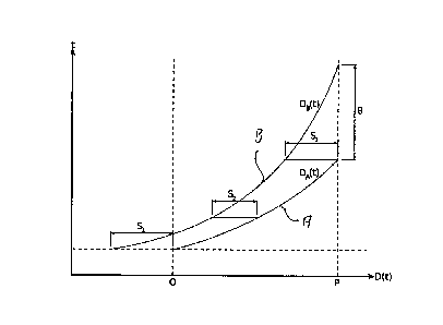
Figure 1 shows two trajectories of landing flights, but only the flying-
distance D in relation to
the flying- time t. Both flights decelerate and, thus, the lines are curved
upward. They both
end at the same point P, but at times separated by O.
The task is to determine O. The separation S has to be greater or equal to the
given a at all
points in time. As an example, three separation values S1 s, and 53 are shown.
The figure 1 also illustrates relevant parts of the trajectories: The first
point in time, where the
minimum separation a has to be ensured, is when the first flight A reaches the
point 0, where
both flights start to use the same route. At that moment, flight B has not yet
reached the start
of the common route 0, but already has to be separated, i.e. S > a. After
flight A lands,
separations and trajectories are not used any longer to ensure safe
operations. Other
measures are more appropriate. Therefore, the moment flight A lands is the
last point in time,
where the minimum separation has to be ensured, i.e. S3 a. In the figure 1, S2
is just an
example of a separation at an arbitrary point in time within the relevant time
interval. In the
illustration it happens to be smaller than S1 and S3.
According to one aspect trajectories are given as a list of nodes defining
points in space and
time each with additional information about the predicted state of the flight
at that point, e.g.
the speed. These nodes are not shown in figure 1 but further explained with
respect to figure
2. On the final part of the approach, these nodes are defined by the local
arrival procedures
which result in a set of flight manoeuvres like e.g. change of altitude (climb
or descend) or
change of speed (acceleration or deceleration).
These trajectory nodes split a trajectory into segments. During each segment
the flight is
assumed to behave in a specific way, such as
- level flight with constant speed,
change of altitude with constant air speed, or
change of speed at a constant altitude.
The trajectory nodes define the start and end conditions for these segments,
which are
explained in figure 2 below.
CA 3065811 2019-12-19
22
For the purpose of the given task the relevant information in a trajectory is
the traversed
distance over ground D(t) as a function of the time t (See Figure 1). The full
3D position is
not needed. It suffices to consider the lengths and flying times of the
segments and the
ground speeds at the trajectory nodes. These are direct results of a typical
trajectory
predictor.
If a trajectory predictor generated regular sampling points, e.g. every 10
seconds, a linear
interpolation between the points would be sufficient assuming constant speed
between
points. Such trajectories would comprise of a large amount of points. Ensuring
separation
with such trajectories would require transferring, storing, and iterating over
them, therefore
impairing performance of the system. It is preferred to handle trajectories
containing points
only where flight behavior changes. Therefore we cannot assume constant speed
between
points. Such points are described as nodes.
Further explanations are given based on figure 2. For the proposed invention,
at least
according to one aspect, we assume that the acceleration within each segment
is constant.
Based on this assumption, a model is used in which the distance over ground
D(t) for each
segment is expressed as a quadratic polynomial and D(t) is a piecewise-defined
function.
This model enables us to perform analytic calculations with segments of
trajectories.
Specifically, it is possible to calculate in closed form the time separation 0
(at the end of both
trajectories) required by a segment of the trajectory A and a segment of the
trajectory B such
that the minimum separation a is obeyed for all times where both segments are
defined.
For this, the following notation is used to describe one trajectory: We use
the index n
(1 n N, where N is the number of segments) to denote the segment which defines
the
trajectory for all t with tn_, < t < 4,, where tn_1 is the time when the
flight will pass the start
node of the segment and tn the corresponding time for the end node. The end
node is thus
the end node for the particular segment and can also be denoted as the
following node. Now
we can express the flying distance for any time t in that interval as
1
D(t) = Dr,(t ¨ tn) = ¨2an(t ¨ tn)2 + vri(t ¨ tn) + dn , (1)
CA 3065811 2019-12-19
23
where an is the acceleration throughout the segment n, vn the ground speed at
the end node
(i.e. when t = tn), and dn the flying distance at the end node. The function D
(t) is defined
piece-wise as D (t) = Dn(t ¨ tn) where tn_1 < t < tn for each n.
Figure 2 illustrates three segments. The middle one with index n ¨ 1 is a
segment of constant
speed, i.e. an_, = 0 and v_1n = vn-2.
We require continuity, i.e. dn_, = Dn(tn_ ¨ tn) , but no differentiability of
the complete
function D (t). Also, the speeds have to be positive at every point in time.
Let us choose the function D (t) to be zero when the flight arrives at the
point P (the runway).
This can be achieved by shifting all the dn of one trajectory by a constant
value. D (t) may
113 then be interpreted as the negative distance to go (DTG) of the flight
at the time t.
It has to be noted, that even though this model corresponds to the laws of
physics, this is still
an approximation: In climb or descend, the Indicated Air Speed (IAS) is kept
constant, which
has a non-linear relationship with altitude and ground speed. The speeds 12n
are ground
speeds.
It is helpful to illuminate the variations appearing during the task of
determining the time
separation 8, by discussing four examples which are shown in figure 3. The
required
separation a is represented by several horizontal black bars of the same
lengths. This way it
can be easily compared with the distance S of the flights.
In example a), let the two flights A and B land with the same speed and
altitude profile. I.e. at
a given distance from the runway, both flights will have the same given ground
speed. Also,
both flights will only decelerate.
At any point in time the second flight B will be further away from the runway
and therefore be
faster than the first flight A. From this it is immediately clear, that the
distance S of the flights
will always decrease with increasing time. Therefore, the moment of closest
approach of flight
B and flight A will be the time, when flight A lands, which is marked with 0-
in figure 3 which
corresponds to S3 in figure 1.
CA 3065811 2019-12-19
24
Note the optical illusion: The curve representing the trajectory of flight A
seems to be steeper
than that of flight B. This can be verified to be an illusion with a ruler by
measuring the vertical
distance of the lines at several points: They are equal.
In example b), the two flights start with the same speed at point R. Let
flight A use a landing
speed, which is lower than that of flight B. It is immediately clear, that
flight A will always be
slower than flight B at the same point in time. The same reasoning as in
example a) applies.
In both examples, it is sufficient to ensure that flight B is at least the
distance a from the
runway, when flight A lands. Therefore, a planning tool shall use the time
separation 0
calculated as the flight duration of flight B for this last part of its
approach of length a.
These examples might lead to the assumption that it is always sufficient to
ensure the
separation a at the point in time when the first flight A lands and that the
time separation
may always be calculated by determining the flight duration of the second
flight B for the last
a-length of its approach. On the other hand, figure 1 already suggested
otherwise: There
clearly is an earlier point in time where the two curves have a minimal
horizontal distance -
namely S2.
In example c), the two flights A and B have the same speed at point R. The
first flight A does
not reduce speed and lands with the same speed. However, the second flight B
reduces
speed starting at point R.
The moment flight B starts decelerating, the distance between the two flights
increases.
Therefore, the minimum separation a has to be ensured at the point in time
when flight B
reaches point R. The time separation 6 may in this case be calculated as the
flight duration of
flight B from point R to point P reduced by the flight duration of flight A
from a point which is
the distance a from point R to point P.
The example c) shows that it is not sufficient to use flight durations of the
second flight B.
However, it might still suggest, that in all cases a fixed point on the route
may be found,
where the check has to be performed.
CA 3065811 2019-12-19
25
This turns out to be wrong as example d) shows: As in example c), the flights
A and B start
with the same speed. Both flights reduce speed starting at point R. However,
flight A reduces
a little and flight B reduces a lot.
When flight A arrives at point R, it will start reducing speed. Once flight B
arrives at point R,
flight A is slower than flight B. Flight B now starts reducing speed, but is
still faster than flight
A for a while. Therefore, the distance between the two flights will reduce
further. Since flight B
reduces its speed faster than flight A, both flights will at one point have
equal speeds, unless
flight A reaches point P first ¨ which we assume not to be the case for this
example. That
moment in time where both have equal speeds will be the moment of closest
approach of the
113 two flights. The distance between flight A and flight B will increase
afterwards, since flight B
will gradually become slower than flight A.
If flight A reaches the runway before the moment of equal speed, we can
proceed as in
example a) an b) for the calculation.
The moment of equal speeds is highly dependent on the flight profiles of both
flights and on
.. the separation of the flights: Enlarging the separation will shorten the
distance flight B has to
slow down before flight A lands and it will decrease the speed of flight A
when flight B passes
point R and starts to reduce speed, thereby enlarging the speed difference
flight B has to
compensate.
It directly follows from this last example that the time separation 0
necessary to ensure the
required minimum separation a has to be calculated based on a point in time
tmin of closest
approach, which may be anywhere in the common definition interval of both
trajectories. The
time tint, depends not only on the flight profiles of the two flights, but
also on the required
and/or predetermined separation a or ¨ equivalently ¨ the resulting time
separation 0.
Note, that there was no reference to segments defining the trajectories of
flight A and B. If the
points R and P are, respectively, the start and end node of a single segment
of the trajectory
of flight A as well as of a single segment of the trajectory of flight B, the
examples still apply.
Therefore, example d) shows that the point in time tmin of closest approach
may be a point
not given by a start node or end node of a trajectory segment. Therefore, just
checking at the
start and end points is not sufficient.
CA 3065811 2019-12-19
26
Figure 4 basically illustrates how the determination function is found and how
it is used.
Therefore, figure 4 shows a general flow chart 400 beginning with a definition
block 402. In
the definition block 402 the first and second trajectories are defined and
according to the
illustrated aspect these are defined as distance functions for the first and
the second flight
trajectory and thus for the first and the second flight. For the first flight
trajectory there is
defined the distance function DA (t). For the second flight trajectory there
is defined the
distance function DB(t, 0). Accordingly, the first distance function DA does
not depend on the
arrival time difference 0 but the second distance function DB depends on the
arrival time
difference 0. The arrival time difference e can also be denoted as time
separation 0 at the
runway. Both expression are synonyms in this description.
Based on these definitions the separation function S(t, 0) is defined as a
difference between
the first and second distance functions. This is done in the separation block
404.
Based on that a further step is performed in the boundary check block 406. In
the boundary
check block 406 the first step, which is illustrated in figure 4 in the
boundary check block 406,
is to differentiate the separation function received from the separation block
404 with respect
to time. The result is evaluated at the boundary times of overlapping
segments, i.e. of the
validity intervals of the considered analytic expressions for the separation
function. The signs
of the results indicate the positions of local minimum points tint, of the
separation function
which may be situated at boundary times or within a validity interval.
Depending on this
result, the minimum point tmit, is determined in the minimum point block 408
either as the
indicated boundary time or as the result of setting the derivative of the
separation block
obtained in the boundary check block 406 to zero and resolving for the time in
order to
receive an analytic expression for the minimum point tmin. In the minimum
point block 408 it
is thus illustrated that the point in time of minimum distance tmin is
dependent on the arrival
time difference 6 and accordingly the minimum point block 408 shows tmin(0).
This minimum time point tmin is than inserted in the separation function in
order to further
receive an analytic expression of the separation function. This analytic
expression for the
separation function is than independent of time as the analytic expression for
the time of
minimum distance tmin is inserted, which depends on O. That is shown in the
time eliminated
block 410. According to that, the separation function S(tmin(0), 0) with
eliminated time is
described as an analytic expression which only depends on 0. For any 0 the
value
S(tmin(0), 0) of is the minimum value of the separation function.
CA 3065811 2019-12-19
27
The next step is to set this analytic expression for the separation function
S(tmin(0), 0) equal
to the predetermined minimum separation a. This is illustrated in the minimum
condition block
411. A further step it to resolve this equation to get an analytic expression
for calculation the
arrival time difference 0. This is basically the determination function and
thus this further step
is illustrated in the determination block 412. According to the determination
block 412 the
determination function is an analytic expression for calculating the arrival
time difference
= f(o-). This determination function is still an analytic expression but there
might be more
than one determination functions depending on rules and conditions.
Particularly, results of
the boundary check block 406 and resolving the analytic expression for the
separation
function according to the time eliminated block 410 results in a plurality of
determination
functions. These determination functions depending on rules and conditions are
described
further below in more detail.
The determination function or determination functions according to the
determination block
412 depend on the general description of the flight trajectories according to
the definition
block 402, but do not depend on particular flight trajectories, i.e. do not
depend on particular
values of flight trajectories. Accordingly, the steps from the definition
block 402 to the
determination block 412 only need to be done once. Accordingly, these steps,
in particular
any resolving steps, may be complicated or at least be done offline. In order
to now use the
determination function to calculate a particular value for the arrival time
difference 8 for a
particular pair of flight trajectories the calculation block 414 is provided.
Besides receiving the
determination function from the determination block 412 the calculation block
also receives
individual flight trajectories, in particular individual distance functions
from the data block 416.
The data block 416 thus constantly or at least frequently and/or repeatedly
provides new
individual data.
Accordingly, the calculation block 414 uses the determination function which
is basically an
analytic expression for each determination function and applies this to the
individual flight
trajectories received from the data block 416. The result is a particular
arrival time difference
0, i.e. a particular value for the arrival time difference 0. Based on that
the second flight
trajectory of the pair of flight trajectories which the calculation block 414
has just received
from the data block 416 can be amended such that its arrival time is deferred
by this arrival
time difference 0 with respect to the arrival time of the first flight
trajectory of the same pair of
flight trajectories.
CA 3065811 2019-12-19
28
Accordingly, the particular value for the arrival time difference 0 is the
output of the
calculation block 414 and the process then returns to the data block 416 in
order to provide a
new pair of flight trajectories in order to calculate a new arrival time
difference 0. In such new
pair of flight trajectories the first flight trajectory may be the second
flight trajectory of the
previous pair of flight trajectories.
It is to be noted that the calculation block 414 may comprise a plurality of
calculation loops
which will be explained with respect to figure 5.
Accordingly, the iteration flow chart 500 basically represents the calculation
block 414 of
figure 4. It starts with a data block 516 which may indeed be identical to the
data block 416. It
provides a pair of flight trajectories and delivers this data to the
initialisation block 502. In the
initialisation block 502 there is calculated as a starting value a minimum
arrival time
difference 00. This initial or minimum arrival time difference 00 is
characterized by the index 0
(zero) in order to indicate that this can be understood as an initial value in
the following
iteration loop. However, one starting value for this minimum arrival time
difference may be
calculated as a flight duration of the second aircraft for a final part of its
flight trajectory of
length equal to the predetermined minimum separation before reaching the
runway.
Accordingly, the initial arrival time difference 00 depends on the
predetermined minimum
separation a.
This starting value is passed to the segments determination block 504. In the
segment
determination block 504 a pair of trajectory segments is determined.
When first using this segment determination block 504 an index i is
initialized with 1 and the
first pair of trajectory segments comprises the segment of the first flight
trajectory having the
runway as one node and the segment of the second flight trajectory which
contains the point
with remaining flying distance equal to the predetermined minimum separation
a. In other
words, when first applying the segment determination block 504 the first pair
of segments
comprises the segment of the first flight trajectory of the last part of the
flight trajectory.
During each subsequent use of the segment determination block 504 the index i
is increased
by one and either for the first trajectory or the second trajectory or both
the current trajectory
segment is exchanged by a new current trajectory segment. The new trajectory
segment is
chosen such that the current trajectory segment and the new current trajectory
segment are
CA 3065811 2019-12-19
29
connected by having a common node and the new trajectory segments of both
trajectories
overlap in the time domain. For this, the node times of the start nodes of the
current
trajectories under the assumption that the second trajectory is parametrized
with the previous
value of the minimal arrival time difference 0i_i are compared and the current
trajectory
segment with the larger node time is exchanged with a new trajectory segment.
Both are
exchanged at the same time only if the common node connecting the current and
the new
trajectory segments have the same node time for the first and the second
trajectory,
Based on this pair of segments a new minimum arrival time difference 0i is
calculated. This
new minimum arrival time difference 0i can also be named as minimal value of
the arrival
time difference. It is thus calculated an arrival time difference as small as
possible to still
ensure that the minimum separation a is ensured for the current pair of
segments. This is
done in the parameter calculation block 506. The result is forwarded to the
comparison block
508. In the comparison block 508 the new and the previous value of the minimal
arrival time
difference 0i_1 are compared and the bigger one is taken. Accordingly, if in
the comparison
block 508 it was found that the new minimum value of the arrival time
difference, i.e. the one
just calculated in the parameter calculation block 506, is smaller than the
old one, the new
one 0, is increased to the old one 0j_1. That is done in the allocation block
510. Otherwise,
the old value will not be changed.
The flow chart goes further to the all pairs block 512. In the all pairs block
512 it is evaluated
whether all possible pairs of segments for the current two flight trajectories
have been
considered. If not, the all pairs block 512 branches back to the segment
determination block
504. Otherwise, it goes on to the final block 514. In the final block 514 the
value of the arrival
time difference 0 is set to the current new value of the minimal arrival time
difference O. In
other words in the final block the arrival time difference will be set to the
maximum value of all
minimal values of the arrival time difference of all minimal arrival time
differences calculated
in the parameter calculation block 506 or the initialisation block 502. The
result is output as
the arrival time difference 0 and can be used to adjust the current second
flight trajectory.
It is to be noted that the iteration flow chart 500 does not seem to receive
an input from the
determination block 412 according to figure 4. However, figure 4 is just
illustrating that the
blocks 402 to 412 make an offline calculation and the result is then used for
the online
calculation. In other words the result, i.e. the plurality of determination
functions, calculated in
the determination block 412 are implemented basically in the parameter
calculation block 506
as fixed determination functions, i.e. being defined in an analytical way by
analytic
CA 3065811 2019-12-19
30
expression. Accordingly, for calculation or adjusting one flight trajectory
after another of each
current pair of flight trajectories is basically only done by using the
calculation illustrated by
the iterative flow chart 500.
The parameter calculation block 506 comprises of steps and decisions which
will be
explained with respect to Figure 6.
Accordingly, the parameter calculation flow chart 600 represents the parameter
calculation
block 506 of figure 5. It starts with the segments determination block 604
which may indeed
be identical with the segments determination block 504. It provides a pair of
trajectory
segments, one from the first trajectory and one from the second trajectory to
the boundary
choice block 606. Block 604 ensures that this pair of trajectory segments
overlaps as
described for the segments determination block 504.
In the boundary choice block 606 it is checked whether the segment of the
first trajectory
determines the beginning of a common validity interval of both segments. If
yes, it is
continued with the first boundary calculation block 608, otherwise, with the
second boundary
calculation block 612. In the first boundary calculation block 608 a
determination function
fbA(u) is evaluated as a candidate minimum arrival time difference Oi. In the
following
candidate evaluation block 610 it is checked whether this candidate Oi is a
valid choice by
checking if the segment of the first trajectory determines the beginning of
the common validity
interval of both segments under the assumption that the adjustable trajectory
parameter (6)
of the second trajectory is chosen as the candidate Oi. If this is the case,
the candidate is
handed to the boundary allocation block 614, otherwise the candidate is
rejected and
processing continues with the second boundary calculation block 612.
In the second boundary calculation block 612 a determination function fbB(a)
is evaluated as
the candidate minimum arrival time difference Oh which is handed to the
boundary allocation
block 614. In the boundary allocation block 614 the candidate arrival time
difference 0, is set
to the old arrival time difference 0i_1 if the latter is bigger.
In the following intermediate check block 616 it is checked whether the
separation function
has a minimum within the common validity interval of both segments which is
not at the
boundaries of the common validity interval. If yes, processing continues with
the intermediate
calculation block 618, otherwise the candidate arrival time difference 0, is
the result of the
CA 3065811 2019-12-19
31
parameter calculation block 506. In the intermediate calculation block 618 a
determination
function fm(o-) is evaluated as the candidate minimum arrival time Bred which
in the final
allocation block 620 is compared with the candidate 0, from the boundary
allocation block
614. The larger of the two candidates 0i and 01' is then used as the result of
the parameter
calculation block 506.
In the following further details in particular of formulas used for receiving
the analytic
expressions for the determination functions, i.e. basically the result
according to the
determination block 412 are explained in detail below. The formulas also
include explanations
regarding the conditions and rules to be considered. The formulas also include
explanations
for details illustrated by the iterative flow chart 500 of figure 5 and 600 in
figure 6. It is also
noted that the flow charts 400, 500, and 600 each may use simplified formula
or simplified
variable expressions or parameters for illustrative purposes. In other words
the formulas and
expressions explained below may be different to some formulas or expressions
used with
respect to figures 4, 5, and 6, but still explain the same thing.
The task is to determine the time separation U at the runway, i.e. the arrival
time difference 0,
such that the separation
S(t) = DA(t) ¨ DB(t)
is never below a given required separation a for all points in time t.
One approximate approach would be to estimate a 6 and to check that S(t) CI
for closely
spaced values of t over the valid range of t. If this check fails at one
point, increase 0 and
start over again. Another approach would be to determine the three values S1,
S2, and S3 for
an estimated 6 and for a given pair of segments and stepwise enlarge the
estimate of U as
long as one of them is below a. The suggested method does not do either of
these.
Enlarging 6 means changing at least one of the trajectories of flight A and B.
We choose to
keep the landing time of flight A fixed and adjust the trajectory of flight B
such that it lands
seconds after flight A. Thus, DA(t) is independent of U and DB(t) = DB(t, 0)
depends on O.
I.e. the separation at a given point in time t depends also on 0:
S(t, 0) = DA(t) ¨ DB(t,19).
CA 3065811 2019-12-19
32
As we have shown with example d), the point in time tmin, where the separation
S(t, 0)
reaches its minimum will change with 0: tmin(0).
I.e. it is not possible to determine tmin independently of 0, insert the
result in S(tmin, 0) =
and solve for 0: The resulting 0 would lead to a changed tmiti invalidating
the result for 0.
Nevertheless, this could be the basis for another iterative approach. However,
the suggested
method is more direct:
For one pair of trajectory segments the correct 0 is determined in one
analytic calculation:
The place of minimum of S(tmin, 0) is analytically determined as tmin(0), e.g.
by solving
as(t8)
= o
at
for t. The resulting expression for tmin(0) is then inserted in
S(tmin(0), 0) = o-
w which may then be solved for O. This will eliminate the dependency on t
and give us an
expression for 0 which only depends on a and the parameters defining the form
of S(t, 0).
The results will be given below, after the dependency on the validity
intervals of the trajectory
segments and a number of other parameters and terminology have been defined.
The presented mechanism is still iterative, since this analytic calculation
has to be done for
each overlapping pair of trajectory segments. In contrast to the possible
approaches hinted at
above, only a single calculation is needed for each overlapping pair of
trajectory segments.
For each segment pair, the result is determined analytically.
To further explain the mechanism, let us fix the trajectory of flight A such
that it lands (arrives
at P) at time 0 and vary the trajectory of flight B such that it arrives at
time 0. Since the
functions D(t) were chosen to be zero at P, this may be expressed as
DA (0) = 0
CA 3065811 2019-12-19
33
DB(0,0) = 0
The first equation may be used to fix the parameters tAn and ensure that they
are
independent of O. The second equation helps making the dependency of D(t, 0)
on 8 explicit
by tBn(0) = 8 ¨ At, where AtB, is the positive flying time (time to go) of
flight B from the
end node of segment n to point P. (Similarly: tAn, = ¨AtAm.) This results in:
DB (t, = DBn(t tBn(9)) = DB?* ¨ 8 + &en)
1
= ¨2 aBn(t ¨8 + AtBn)2 + vBn(t ¨ + AtBn) + dBn
DA(t) = DAm(t ¨ tAm) = DAm(t + AtAm)
1
= ¨2 aAm (t + AtAm)2 + vAm (t + &Am) + dAm
Reference numerals shown below in parenthesis refer to blocks in the
structures of figures 5
and 6, i.e. said explained steps or even formulas may be implemented in the
corresponding
block according to the cited reference numeral.
The input into the mechanism are the characteristic parameters describing all
segments of
the first trajectory i.e. of the trajectory of flight A: aAm, vAm, dAm, and
AtAm for all 1 <m NA
and Atm, the characteristic parameters describing the second trajectory i.e.
the trajectory B:
aBn, VBn, den, Atrin for all 1 n < NB and &B0, and the required separation 0-.
Possibly also
parameters restricting the range in which this separation shall be ensured.
Accordingly index
A refers to trajectory A, i.e. the first trajectory and index B refers to
trajectory B, i.e. the
second trajectory. (516)
This is a short overview of the mechanism which is elaborated in the sections
below:
Determine the initial segment n of the trajectory B such that cin_1 <ci 5_ dn
holds. All
segments of trajectory B with larger indices are considered to be handled in
the
following.
Determine an initial 00 with function A(cr) ensuring sufficient separation at
t = ()Error!
Reference source not found.. (502)
Iterate backwards according to an iteration described below handling pairs of
segments starting with segment m = NA of the trajectory A and segment n of
trajectory
B as determined before:
Choose segment m of the trajectory A and segment n of trajectory B such that
CA 3065811 2019-12-19
34
- they overlap and
all segments with higher indices have been handled.
This may always be achieved by decrementing either m, or n, or both. (504)
- If tBn-i(Oi-i) tAm-1 (606), determine OraxA with the determination
function
fbA(o). (608)
- If then OraxA Oi_i holds, let Orax = 0i_i. (614)
- If
OraxA > 9 and ten-i(eraxA) < tAm-1 also holds, let or¨ = oriaxA
(610)
- Otherwise, no 8["1a is found, yet.
If no Or' is found, determine OraxB with the determination function fBB(0-).
(612)
> 0i-1 let 8M ax 0 max13 = or¨ B . (614)
- If no or¨ is found, let or¨ = 0,_,. ( 614)
If the inequalities (12) hold for 0 = or¨ (616), determine ared with the
determination function fni(o-). (618)
Select 0i = max(Or', Ored). (620)
If tBn_i(Oi) tAm_i, the segment m of trajectory A is handled. Otherwise
segment n of trajectory B. (504)
The final 8, is the result of the mechanism. (514)
Even when an iteration leads to an increased time separation > 0) there is
no need to
re-iterate the segments of the trajectories already handled in earlier
iterations.
In an initializing step, 00 is determined such that the second flight B is
exactly the distance a
before the point P at the time 0 when flight A arrives at point P. This may be
done by solving
the following equation for 00:
D8(0, 00) = ¨a
For this, the correct segment n of D8(t,0) may be found with dn_1 < dn, and
with
equation (1) we get:
DB,,(0 ¨ tB7,(00)) = DBn(0 ¨ 00 + AtBn) = ¨a.
CA 3065811 2019-12-19
35
This equation is either quadratic or linear in 00 and therefore has three
possible solutions:
The two signs of the root and the linear case. The solution is the function 00
= fo(o-).
An iteration will be described and from now on we will use the index n for the
current
segment of the trajectory of flight B and the index m for the current segment
of the trajectory
of flight A. The indices are decreased as we iterate backward over the
trajectories. DBn and
DAm are the corresponding functions describing the current segments, aBn, vBn,
dBri, AtBn the
parameters determining DB,, and aAm, vAm, dAm, AtAm the parameters determining
DAm.
The initial index n for t = 0 is the same as the one used when determining 00.
For it holds
tBn_1(00) 0 < tBn(00) =
The initial index m = NA denotes the last segment of the trajectory for which
dAm = 0 and
tAm =Am = 0.
Each iteration i = 1, 2, ... consists of the following steps:
- Determine a 0. Oi_1 as described below.
- Decrease either m if t8_1(0) <
- -Am-i, or n if t8õ_1(01) > tAl or both if tHn_1(81) =
tAm-l=
For each pair n,m, the 0 > Oi_1 will be determined below such that the
separation a is
obeyed for all times t in the common validity interval:
S(t, 0) a for all max(tBn_1(03, tAm_i)
t min(tBn(9i), tAm) . (2)
Assuming the previous check has shown that
S(t, 0i_1) a for all min(tmi(Oi_i), tAm) t < 0 (3)
it follows that
CA 3065811 2019-12-19
36
S(t, o- for all max(tBn_1(0i), tAni_i) t 5_ 0,
(4)
assuming the speed is never negative. This is then the condition (3) for the
next iteration
when incrementing i and decrementing either n or m or both as explained above:
The larger
of tBn-1(91) and tAm_i will become t (9 ) or, respectively, tAm.
The mechanism continues traversing the trajectories backwards toward the
beginning,
decreasing either m or n or both and increasing i, until one of a number of
end-conditions has
been reached. It stops when n or m reaches zero. It may possibly stop, when
other
conditions are satisfied, e.g. when m reaches the point where the predecessor
trajectory
merges with the successor route, or when a maximum DTG is reached by the
predecessor.
When all iterations are done, the last 0, will be our final result. If one of
the trajectories was
fully iterated, it will hold
S(t, 0) a for all max(tB0(00, tA0) t 0 ,
(5)
i.e. for the whole time interval where both trajectories are defined.
Otherwise, in the presence
of other stop-conditions, it will be true for all t where both trajectories
are defined and the
other conditions are satisfied.
A separation of a pair of segments will now be described and it remains to
show, how for a
given pair of indices m and n the 0, is determined which satisfies equation
(2).
With tmm we will denote the point in time where flight A and B have their
closest approach
within the current combined validity interval max(tBn_1(93, tAm_i) t <
min(tBn(0i), tAm) of
the current segments of both trajectories. Unless equation (2) is already
satisfied for 0, =
Oi_i, we will determine Eli > Oi_i such that
S(tmin, Oi) = a (6)
holds. Note, that tmm depends on the form of S as well as on 0.
There are three candidates which have to be considered and checked separately:
CA 3065811 2019-12-19
37
tmmianx= max(tBn-i(9i), tAm_i)
tmit= min(tBn(00, tAm_i)
max(tBn_1(0i), tAm_i) < tgiend < Min(tBn(0i), tAm)
For each candidate for tmin, a 0i may be found which would satisfy equation
(2) if the true
tmin were equal to the candidate. We will call these solutions 014', Orin, and
ored ,
respectively. The largest of these will be the solution 9, since a larger 9
always leads to a
larger S(t, 0) and thus if the largest candidate satisfies equation (2), the
other two candidates
will, as well.. This will automatically determine, which of the candidates is
the true tmin, i.e.
the time of the closest approach within the current combined validity
interval.
For the candidate tmlnn at the end of the interval, equation (3) and
continuity of the function
S(t, 0) directly show that Orin = 0i_i already satisfies equation (2).
The cases "Max" and "Med" will be handled as follows:
The case is handed by inserting
t mm ianx max(tB,,_ ovax),tAm-1)
in equation (2) and solving the equal case of equation (2) for 01':
S(max(tBn-i(Orax), tAm_1), flax) = cr
Due to the maximum, there are two cases, which we call "MaxB" and "MaxA".
It is important to note that tBn-1(0) = 9 ¨ At9n-1 increases together with 9
and may therefore
become greater than tAm_i for a larger 0 when it initially was less or equal
for a smaller 0.
Since we do not know Orax, yet, it is not clear, which of the two cases hold,
and we might
have to check both. Initially, we can only use Oi_i: In the case,
max(tBn_i (6), tAm_i)
=
tAm_i (7)
CA 3065811 2019-12-19
38
for U = 0i_i , we have to start assuming that MaxA is relevant and have to
find the solution
OraxA of the equation
S(tAm_i, OraxA) = 0- . (8)
The solution is the determination function 0 = fbA(CT).
If it results in 0 r axA > 0 we have
to re-check, that equation (7) still holds for 9 = or¨A. If it does not hold,
OraxA is not a valid
candidate for 0i and the case Max6 will result in a valid candidate.
Either if the MaxA case did not lead to a valid candidate, or if
max(t8n_1(0), tAm_i) = tBn-1(0) (9)
already holds for 0 = Oi_i, the case MaxB has to be used: For this, we have to
find the
solution OtlaxB of the equation
S(t8n-1(eraXB), orax6' =
(10)
The solution is the determination function or¨B = .f.3(0-). This will always
satisfy equation
(9) for o = erax13, if oraxs
tBn(0 i-1) = i-1 6,t Bn 9 it, axB A f.
Bn = tBnoltlaxB)
So far the mechanism has determined a 01"ax such that
S(t, 9[4c) a for all t min(tBn(Orax), tAm)
and for t = max(tBn-i(Orax), tAm-i) = (11)
This can only lead to a larger Or ed > e[", if S(t, 0) has a minimum between
the boundaries
of the validity interval, i.e. between max(tBn_i (0), tAm-i) and min(tBn(0),
tAm), which may be
checked with
CA 3065811 2019-12-19
39
(as(t, e) (as(t, ())
> 0 . (12)
at ) < 0 and
at )t=minct,.(0),tAm)
These two conditions are necessary and sufficient due to the quadratic nature
of S(t, 0) for a
given pair of indices m and n. It suffices to check these conditions for 0 =
07'" . They will
then hold for any red > orax
In order to determine the formula for solution Ore" for candidate tgrnd, the
time of the
minimum tmmTnd(6) has to be determined by solving
(as(t,e))
= 0 .
at )Med
t=t (0)
mm
The result 4=60 has to be inserted in
s(tmmrnd (ered), red) = ,
(13)
and solved for Bred. The solution is the determination function Bred =
The step considering a pair m and n therefore results in a 0, 0i_i which is
either 0i =
oi oraxA _ bAlõ\ 0i = oraXB
= bB(a), or 0, = red = fm(a). The analytical expressions
¨ u
for the determination functions fbA, fbB, and fm are obtained by solving
equations (8), (10),
and (13). They only depend on CI and the parameters determining the trajectory
segments
aBn, 1713n, dBn, AtBn, aAm, VAm, dAm, and AtAm and may thus be efficiently
implemented in a
computer program.
CA 3065811 2019-12-19