Sélection de la langue

Search

Sommaire du brevet 3066797 

Énoncé de désistement de responsabilité concernant l'information provenant de tiers

Une partie des informations de ce site Web a été fournie par des sources externes. Le gouvernement du Canada n'assume aucune responsabilité concernant la précision, l'actualité ou la fiabilité des informations fournies par les sources externes. Les utilisateurs qui désirent employer cette information devraient consulter directement la source des informations. Le contenu fourni par les sources externes n'est pas assujetti aux exigences sur les langues officielles, la protection des renseignements personnels et l'accessibilité.

Disponibilité de l'Abrégé et des Revendications

L'apparition de différences dans le texte et l'image des Revendications et de l'Abrégé dépend du moment auquel le document est publié. Les textes des Revendications et de l'Abrégé sont affichés :

  • lorsque la demande peut être examinée par le public;
  • lorsque le brevet est émis (délivrance).
(12) Demande de brevet: (11) CA 3066797
(54) Titre français: APPAREIL COMPRENANT UNE VISIBILITE OPERATIONNELLE ACCRUE AUX FINS D~UTILISATION SUR DES MACHINES D~EXPLOITATION AUTOPROPULSEES
(54) Titre anglais: AN APPARATUS HAVING INCREASED OPERATIONAL VISIBILITY FOR USE ON SELF-PROPELLED OPERATING MACHINES
Statut: Examen
Données bibliographiques
(51) Classification internationale des brevets (CIB):
  • B66F 09/12 (2006.01)
(72) Inventeurs :
  • IOTTI, MARCO (Italie)
(73) Titulaires :
  • MANITOU ITALIA S.R.L.
(71) Demandeurs :
  • MANITOU ITALIA S.R.L. (Italie)
(74) Agent: MBM INTELLECTUAL PROPERTY AGENCY
(74) Co-agent:
(45) Délivré:
(22) Date de dépôt: 2020-01-07
(41) Mise à la disponibilité du public: 2020-07-15
Requête d'examen: 2022-09-15
Licence disponible: S.O.
Cédé au domaine public: S.O.
(25) Langue des documents déposés: Anglais

Traité de coopération en matière de brevets (PCT): Non

(30) Données de priorité de la demande:
Numéro de la demande Pays / territoire Date
102019000000607 (Italie) 2019-01-15

Abrégés

Abrégé anglais


Described is an apparatus (2) for a self-propelled operating machine (10)
comprising a supporting frame (21, 22, 23) designed to be fastened at the
rear to an attaching device wherein an operating arm (102) of the machine
(10) is provided and designed to be coupled at the front to a tool (3).
The frame includes two lateral uprights (21, 22) joined at the top by a
transversal plate (23).

Revendications

Note : Les revendications sont présentées dans la langue officielle dans laquelle elles ont été soumises.


7
CLAIMS
1. An apparatus (2) for a self-propelled operating machine (10)
comprising a supporting frame (21, 22, 23) designed to be fastened
at the rear to an attaching device wherein an operating arm (102) the
machine (10) is provided and designed to be coupled at the front to a
tool (3), wherein the frame includes two lateral uprights (21, 22)
joined at the top by a transversal plate (23).
2. The apparatus (2) according to the preceding claim, wherein the
transversal plate (23) is inclined downwards in the front direction.
3. The apparatus (2) according to any one of the preceding claims,
wherein the uprights (21, 22) are flat parallel to each other equipped
with respective slots (211, 221) for receiving together an element
(33) with an elongate shape for supporting the tool (3).
4. The apparatus (2) according to any one of the preceding claims,
comprising a central plate (25) connected to the transversal plate
(23) and provided with a slot (251) for receiving a element (33) with
an elongate shape for supporting the tool (3).
5. An accessory (1) for a self-propelled operating machine, comprising
an apparatus (2) according to any one of the preceding claims and a
tool (3) designed to be mounted in a removable fashion to the
apparatus (2).
6. The accessory (1) according to the preceding claim, wherein an
element (33) for supporting the tool (3) is elongate in shape and the
accessory (1) includes at least one jaw (41, 42) which can be
removably coupled to the supporting element (33) for locking the tool
(3) to an upright (21, 22) of the apparatus (2).
7. The accessory according to claim 5 or 6, wherein the apparatus (2) is
a fork-carrier and the tool (3) is a fork equipped with prongs (31, 32).
8. The accessory according to the preceding claim, wherein the
transversal plate (23) lies in a plane which defines with a plane of the
prongs (31, 32) an angle of between 20 and 30 degrees.

8
9. The accessory according to the preceding claim, wherein the angle is
between 22 and 24 degrees.
10. The accessory according to the preceding claim, wherein the angle
is substantially equal to 23 degrees.

Description

Note : Les descriptions sont présentées dans la langue officielle dans laquelle elles ont été soumises.

1
DESCRIPTION
IMPROVED APPARATUS
This invention relates to improved apparatus designed to be used on self-
propelled operating machines, in particular telescopic lifts or
"telehandlers".
In particular, the invention may be an improved fork-carrier, with increased
operational visibility.
Accessories are known in the prior art which are designed to be mounted
on the telescopic operating arm of telehandlers in order to move loads.
Amongst the most common accessories there are forks, side transfer
units, winches, jib arms, etc.
Various accessories comprise a supporting structure which is designed to
attach in a removable fashion to a coupling device which is fitted to the
operating arm is provided and which carries the tool which engages the
load.
In particular, the accessory commonly known as "forks" or "fork" includes a
structure or frame known in the jargon of the trade as "fork-carrier", to
which the forks are coupled, that is to say, the tool equipped with prongs
for inserting pallets or bales of hay or the like on forks.
More in detail, according to a prior art solution, the prongs of the fork are
slidably mounted on a pin or central supporting element which is inserted
in suitable lateral slots of the fork holder.
The prior art supporting frame T, which may also be sold separately, is
rectangular and has a thick upper tubular crosspiece Q, for example with a
quadrangular cross section, as shown in Figures 1 and 2.
The tubular crosspiece Q has a plurality of centring holes which allow, by
means of suitable pins P, usually four in number, the prongs R to be
locked correctly in position at their above-mentioned pin U, avoiding their
sliding.
The prongs R may be tilted onto the forks T, in such a way as to reduce
the overall size of the accessory during transport (see Figure 6); for this
CA 3066797 2020-01-07

2
reason, use is made of chains for securing the prongs and keeping them
in the tilted configuration.
Although this solution is currently used in practice, it has some limitations
which, in certain circumstances, make it difficult to use and which will be
explained below with the aid of Figure 3.
In order to be able to correctly insert forks in a load which is rested on the
ground, the operator of the telehandler 10 needs to see how the tips of the
prongs R of the forks are positioned relative to the load, so as to insert
them in the correct manner in the base pallet.
However, the structure of the current fork-carriers T, with reference in
particular to the above-mentioned upper crosspiece Q, creates at the
ground, or in any case at the plane of the prongs R, non-visible intervals
Ni, N2 relative to the view point of the operator in the cabin, which occupy
a significant area of the zone in front of the tips.
For this reason, currently, in order to be able to correctly pick up the load,
the operator, after having moved the forks towards the load, might have to
control the inclination of the forks in such a way as to make the tips
visible,
in order to have an idea of their relative position, and then redirect the
forks and insert them in the pallet "blind", just using the approximate idea
of the position of the tips which has been obtained before.
These manoeuvres are inconvenient and the need is therefore felt in the
market for a telehandler apparatus with improved visibility which
overcomes the limits of the prior art.
The technical purpose which forms the basis of the invention is to provide
an improved apparatus which satisfies the above-mentioned need.
The specified aim is attained by the invention made according to claim 1.
Further features and advantages of the invention are more apparent in the
non-limiting description of a preferred embodiment of the accessory which
includes the apparatus, as illustrated in the accompanying drawings, in
which:
Figures 1 and 2 are axonometric views of the prior art apparatus;
CA 3066797 2020-01-07

3
- Figure 3 is a side view of the prior art apparatus when it is attached
to the operating arm of a telehandler;
- Figures 4 and 5 are perspective views of the apparatus according to
the invention;
- Figures 6 and 7 are side views of the apparatus according to the
invention and of the prior art in the relative transport operating
configurations; and
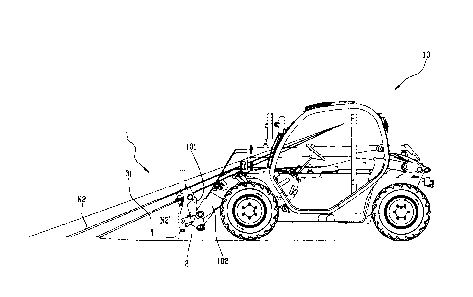
Figure 8 is a side view of the proposed apparatus mounted on the
operating arm of a telehandler.
With reference to the accompanying drawings, the numeral 1 denotes in
its entirety an accessory for self-propelled operating machines 10 which
comprises an apparatus 2 according to the invention and a tool 3 carried
by the apparatus.
More specifically, in the example shown, the apparatus 2 is an improved
fork holder designed for use with a telehandler 10 and the tool is a fork for
lifting loads, however, the inventive concept of the invention may also be
incorporated in different apparatuses.
The apparatus 2 proposed comprises a supporting frame 21, 22, 23
preferably quadrangular in the shape of a frame, designed to be attached
at the rear to a device 101 for connecting the operating arm 102 of the
machine 10, for example by means of the rear tubular element labelled 24
in the drawings.
Moreover, the apparatus 2 is designed to be coupled at the front and to
support the tool 3.
It should be noted that the expression "at the front" referred to the
apparatus 2 refers to its side (or face) opposite the machine 10 and the
arm 102, whilst the expression "at the rear" refers to the opposite side.
According to an important aspect of the invention, the frame of the
apparatus 2 includes two side uprights 21, 22, for example two plates,
joined at the top by a transversal plate 23, instead of the tubular element
of the prior art.
CA 3066797 2020-01-07

4
More specifically, the transversal plate 23 is inclined downwards in the
front direction, preferably to form with the longitudinal axis of extension of
the uprights 21, 22 a lower acute angle.
More in detail, if the tool 3 is a fork, the plate 23 which acts as an upper
crosspiece lies in a plane which can define with the plane on which the
prongs 31, 32 lie an angle of between 20 and 30 degrees and preferably
between 22 and 24 degrees; still more preferably, the angle is
substantially equal to 23 degrees.
As mentioned above and as shown in Figures 4 and 5, the uprights 21, 22
may be two plates which are parallel to each other and are provided with a
respective slot 211, 221 for simultaneously receiving an elongate
supporting element 33 of the tool 3.
If the tool 3 is a fork, the supporting element 33 may be the tubular
element, preferably circular, on which the prongs 31, 32 are mounted
which, as explained in the description of the prior art, may be slidably
associated with it.
Moreover, there may be a central plate 25 connected to the transversal
plate 23 and perpendicular to it, which is also equipped with a slot 251 for
receiving the supporting element of the tool 3.
Preferably, the invention includes two jaws 41, 42, which can be
removably coupled to the supporting element, for example by using
butterfly screws, for locking the tool 3 to the uprights 21, 22 of the
apparatus 2.
In practice, the cylindrical ends of the prongs 31, 32, which are inserted on
the supporting pin 33, are closed in a sandwich-like fashion between the
jaws 41, 42 and the uprights 21, 22, which constitute two side walls;
alternatively, the above-mentioned cylindrical ends may be closed
between two jaws in any position along the pin 33.
The operation of the invention is explained below with reference to the
accompanying drawings, by which a comparison may be made between
the prior art and the invention.
CA 3066797 2020-01-07

5
The numerals NI and N2' in Figure 8 denote two non-visible intervals for
the cabin operator in the case of use of the apparatus 2 according to the
invention.
From a comparison between Figures 3 and 8 it is immediately clear that
the non-visible intervals Ni', N2' of the apparatus 2 proposed, especially
at or close to the tips of the prongs 31, 32 of the fork, are significantly
reduced compared to those of the prior art equipment, with obvious
advantages in terms of safety and ease of use.
In effect, thanks to the adoption of the upper crosspiece defined by the
transversal plate 23, the view point of the operator who observes the load
to be forked when it has carried the accessory in close proximity to it is far
less obstructed than that of the traditional apparatuses.
In this way, it is possible to avoid the operator having to make those
inconvenient and inefficient operations prior to the gripping of the load
which were mentioned during the discussion of the prior art.
Further, having eliminated the tubular crosspiece and having implemented
the configuration according to the invention, it is also possible to have a
greater degree of tilting of the tool 3 on the apparatus 2, thereby obtaining
a smaller overall size of the accessory 1 during road transport.
In effect, as can be seen by comparing Figures 6 and 7 it is clear that the
invention allows the forks 3 to be tipped with a front angle between these
and the apparatus 2 which is significantly greater than the tipping angle of
the prior art.
It should also be noted that the fixing operation is safer because the
barycentre of the forks 3 according to the invention is located in a position
in which it tends to keep them in the tilted configuration.
In order to keep the prongs 31, 32 in the tilted position, suitable brackets
are provided, which replace the prior art chains; the brackets, when not
used, can simply be anchored to the rear of the apparatus 2, with obvious
advantages in terms of convenience for the operator.
CA 3066797 2020-01-07

6
It should also be noted that having adopted the locking in position of the
prongs 31, 32 to the tubular element for supporting the forks using jaws
41, 42 which can also be removed manually, especially if they are
clamped using butterfly screws, it is much easier to fit and dismantle, but
above all it allows the apparatus 2 to be fitted with tools even of different
sizes and to better adjust the relative position in which they are to be
applied to the apparatus 2.
Lastly, according to an advantageous preferred feature of the invention,
the apparatus 2 is equipped with a load-supporting grid 5 which is
removable, for example by means of bolts which join it to the transversal
plate 23, unlike the prior art which uses a grid welded to the upper tubular
crosspiece.
In this way, not only is it possible to choose when to use it and when not
to, giving priority either to a firm resting of heavy loads on the grid or to
visibility, but the grid 5 is also easily replaced in the case of damage.
CA 3066797 2020-01-07

Dessin représentatif
Une figure unique qui représente un dessin illustrant l'invention.
États administratifs

2024-08-01 : Dans le cadre de la transition vers les Brevets de nouvelle génération (BNG), la base de données sur les brevets canadiens (BDBC) contient désormais un Historique d'événement plus détaillé, qui reproduit le Journal des événements de notre nouvelle solution interne.

Veuillez noter que les événements débutant par « Inactive : » se réfèrent à des événements qui ne sont plus utilisés dans notre nouvelle solution interne.

Pour une meilleure compréhension de l'état de la demande ou brevet qui figure sur cette page, la rubrique Mise en garde , et les descriptions de Brevet , Historique d'événement , Taxes périodiques et Historique des paiements devraient être consultées.

Historique d'événement

Description Date
Modification reçue - modification volontaire 2024-04-04
Modification reçue - réponse à une demande de l'examinateur 2024-04-04
Rapport d'examen 2023-12-06
Inactive : Rapport - Aucun CQ 2023-12-05
Lettre envoyée 2022-11-01
Exigences pour une requête d'examen - jugée conforme 2022-09-15
Toutes les exigences pour l'examen - jugée conforme 2022-09-15
Requête d'examen reçue 2022-09-15
Représentant commun nommé 2020-11-07
Demande publiée (accessible au public) 2020-07-15
Inactive : Page couverture publiée 2020-07-14
Requête pour le changement d'adresse ou de mode de correspondance reçue 2020-05-08
Lettre envoyée 2020-03-02
Inactive : Conformité - Formalités: Réponse reçue 2020-02-21
Réponse concernant un document de priorité/document en suspens reçu 2020-02-21
Inactive : Transfert individuel 2020-02-21
Inactive : CIB attribuée 2020-02-14
Inactive : CIB en 1re position 2020-02-14
Lettre envoyée 2020-02-03
Exigences de dépôt - jugé conforme 2020-02-03
Exigences applicables à la revendication de priorité - jugée conforme 2020-01-30
Lettre envoyée 2020-01-30
Demande de priorité reçue 2020-01-30
Représentant commun nommé 2020-01-07
Inactive : Pré-classement 2020-01-07
Demande reçue - nationale ordinaire 2020-01-07
Inactive : CQ images - Numérisation 2020-01-07

Historique d'abandonnement

Il n'y a pas d'historique d'abandonnement

Taxes périodiques

Le dernier paiement a été reçu le 2023-12-22

Avis : Si le paiement en totalité n'a pas été reçu au plus tard à la date indiquée, une taxe supplémentaire peut être imposée, soit une des taxes suivantes :

  • taxe de rétablissement ;
  • taxe pour paiement en souffrance ; ou
  • taxe additionnelle pour le renversement d'une péremption réputée.

Les taxes sur les brevets sont ajustées au 1er janvier de chaque année. Les montants ci-dessus sont les montants actuels s'ils sont reçus au plus tard le 31 décembre de l'année en cours.
Veuillez vous référer à la page web des taxes sur les brevets de l'OPIC pour voir tous les montants actuels des taxes.

Historique des taxes

Type de taxes Anniversaire Échéance Date payée
Taxe pour le dépôt - générale 2020-01-07 2020-01-07
Enregistrement d'un document 2020-02-21
TM (demande, 2e anniv.) - générale 02 2022-01-07 2021-12-23
Requête d'examen - générale 2024-01-08 2022-09-15
TM (demande, 3e anniv.) - générale 03 2023-01-09 2022-12-19
TM (demande, 4e anniv.) - générale 04 2024-01-08 2023-12-22
Titulaires au dossier

Les titulaires actuels et antérieures au dossier sont affichés en ordre alphabétique.

Titulaires actuels au dossier
MANITOU ITALIA S.R.L.
Titulaires antérieures au dossier
MARCO IOTTI
Les propriétaires antérieurs qui ne figurent pas dans la liste des « Propriétaires au dossier » apparaîtront dans d'autres documents au dossier.
Documents

Pour visionner les fichiers sélectionnés, entrer le code reCAPTCHA :


Pour visualiser une image, cliquer sur un lien dans la colonne description du document. Pour télécharger l'image (les images), cliquer l'une ou plusieurs cases à cocher dans la première colonne et ensuite cliquer sur le bouton "Télécharger sélection en format PDF (archive Zip)" ou le bouton "Télécharger sélection (en un fichier PDF fusionné)".

Liste des documents de brevet publiés et non publiés sur la BDBC .

Si vous avez des difficultés à accéder au contenu, veuillez communiquer avec le Centre de services à la clientèle au 1-866-997-1936, ou envoyer un courriel au Centre de service à la clientèle de l'OPIC.


Description du
Document 
Date
(aaaa-mm-jj) 
Nombre de pages   Taille de l'image (Ko) 
Description 2024-04-03 6 340
Revendications 2024-04-03 1 65
Dessins 2024-04-03 6 231
Revendications 2020-01-06 2 46
Dessins 2020-01-06 6 117
Description 2020-01-06 6 220
Abrégé 2020-01-06 1 9
Dessin représentatif 2020-06-21 1 14
Modification / réponse à un rapport 2024-04-03 22 885
Courtoisie - Certificat de dépôt 2020-02-02 1 576
Courtoisie - Certificat d'enregistrement (document(s) connexe(s)) 2020-03-01 1 334
Courtoisie - Réception de la requête d'examen 2022-10-31 1 422
Demande de l'examinateur 2023-12-05 5 297
Nouvelle demande 2020-01-06 6 123
Avis du commissaire - Demande non conforme 2020-01-29 2 193
Document de priorité 2020-02-23 1 36
Requête d'examen 2022-09-14 5 123