Note : Les descriptions sont présentées dans la langue officielle dans laquelle elles ont été soumises.
-1-
MACHINE DEBRIS CLEAN OUT SYSTEM
BACKGROUND OF THE INVENTION
1. Field of Invention
The present invention relates generally to machining and in particular to a
method and apparatus for removing debris from a machining location.
2. Description of Related Art
Mills and lathes are common machining equipment that is utilized in modern
machine shops to form and build a variety of parts. Such machines may be
utilized to cut or remove material from a block of raw material to form the
finished or intermediate piece. The material thus removed from the raw
material is often referred to a cuttings, shavings or chips. Such chips are
known to accumulate under the machining location which require frequent
removal by an operator.
Conventional methods of removing cuttings from beneath a machining
location have not been satisfactory. In particular, traditionally an operator
would stop the operation of the tool to remove the chips from thereunder. It
will be appreciated that such work stoppage is time consuming to perform
resulting in lost productivity. This lost productivity has been exacerbated in
recent years with the increasing use of computer numerically controlled (CNC)
machines which may operate without significant ongoing operator supervision.
In particular, as such CNC machines may be expected to operate for 24 hours
a day, the accumulation of chips therein is greatly increased.
One common solution to the build-up of chips has been to provide spray
nozzles directing a flow of cutting fluid or the like at the surface under the
tool
so as to direct or otherwise move the chips to a collection point.
Disadvantageously, such nozzles may have difficulty covering the entire area
below a machining location and may therefore be prone to leaving piles of
chips in the corner of the machine bed or at other locations.
Date Recue/Date Received 2020-07-10
-2-
SUMMARY OF THE INVENTION
According to a first embodiment of the present invention there is disclosed an
apparatus for removing debris from under a machining location comprising a
collection surface located below the machining location having a curved
portion laterally offset from the machining location and a fluid discharge
positioned above the transition portion adapted to periodically discharge a
fluid therefrom so as to be guided by the transition portion across the
collection surface to sweep the debris towards a collection point.
The fluid discharge may comprise a reservoir having an interior adapted to
contain a quantity of a fluid, a fluid source operable to introduce a quantity
of
fluid into the reservoir and an actuator operable to transition the reservoir
from
a first configuration retaining the fluid therein and a second configuration
releasing the fluid therefrom.
The reservoir may include an open top. The reservoir may include a pivot
support so as to permit the reservoir to be rotated between the first
configuration wherein the open top is oriented substantially upward to the
second configuration wherein the reservoir is rotated to permit fluid to be
discharged through the open top. The actuator may be operable to rotate the
reservoir between the first and second positions. The open top of the
reservoir may be oriented towards the transition portion in the second
configuration.
The fluid discharge may comprise a reservoir having an interior adapted to
contain a quantity of a fluid, a fluid source operable to introduce a quantity
of
fluid into the reservoir and a port extending through the reservoir wherein
the
port is closed in the first configuration and open in the second
configuration.
The port may include a valve.
The transition portion may comprise a curved surface. The collection surface
may include a rear wall extending substantially upward from the transition
Date Recue/Date Received 2020-07-10
-3-
portion. The collection surface may include a bottom portion extending from
the transition portion under the machining location. The bottom portion may
extend from the transition surface to a collection location. The collection
location includes a conveyor therein adapted to remove the debris from the
machine enclosure.
According to a further embodiment of the present invention there is disclosed
a
method for removing debris from a machining location comprising introducing
a fluid from a fluid source into an interior of a reservoir and periodically
discharging the fluid from the interior of the reservoir onto a transition
surface
positioned offset from the machining location
Other aspects and features of the present invention will become apparent to
those ordinarily skilled in the art upon review of the following description
of
specific embodiments of the invention in conjunction with the accompanying
figures.
BRIEF DESCRIPTION OF THE DRAWINGS
In drawings which illustrate embodiments of the invention wherein similar
characters of reference denote corresponding parts in each view,
Figure 1 is a perspective view of a system for removing debris from
under a
machining location according to a first embodiment of the present
invention.
Figure 2 is a side view of the system of Figure 1 at a first or
filling position.
Figure 3 is a side view of the system of Figure 1 at a discharge position.
Figure 4 is a side view of the system of Figure 1 showing the fluid
source
and filling system.
Figure 5 is a side view of the system of Figure 1 according to a
further
embodiment of the present invention at a first or filling position.
Figure 6 is a side view of the system of Figure 1 according to a further
embodiment of the present invention at a second or discharge
position.
Date Recue/Date Received 2020-07-10
-4-
DETAILED DESCRIPTION
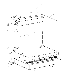
Referring to Figure 1, an apparatus for removing machining chips according to
a first embodiment of the invention is shown generally at 10. The apparatus
may be located within or below a machine having a machining location 8.
5 The machining location includes at least one tool (not shown) adapted to
perform a machining operation. As utilized herein, machining location refers
to any position in which a machining operation is conducted. Such machining
operations may be conducted by any known machining tool including but are
not limited to mills, lathes, drills and saws. As utilized herein, machining
chips
10 shall refer to any portion of material removed from the base material by
such
machining operations as may be commonly referred to as chips, swarf,
turnings, filings or shavings.
The apparatus comprises a receiving surface 12 below the machining location
and fluid discharge adapted to receive a fluid from a fluid supply such as a
pipe 36 thereabove. As illustrated herein the fluid discharge may comprise a
reservoir 40 or 60 adapted to release a quantity of fluid as described below.
It
will be appreciated that other intermittent fluid release systems may also be
useful as well. The receiving surface 12 comprises a planar material
preferably having a bottom portion 14 extending to a free distal edge 15 below
the machining location 8. As illustrated in Figures 1 through 4, the machine
may include a rear wall 16 and/or side walls 18 (only one of which is shown in
Figure 1 for clarity). The receiving surface 12 may include a transition
portion
20 adjacent to the rear wall 18 so as to be between the rear wall and the
bottom portion 14. As illustrated, the transition portion may be curved or
arcuate although it may also be angular or a corner intersection of the rear
wall 16 and bottom portion 14. The bottom portion 14 may have an angle 22,
as illustrated in Figure 4 and the transition portion 20 may have a radius,
generally indicated at 24 so as to optimize the transition from vertical to
horizontal movement of the fluid discharged from the reservoir 40. The angle
may be selected to be any angle which assists such flow of fluid and
similarly,
the radius 24 may be selected to be any radius which enhances flow of the
fluid between the rear wall and the bottom portion.
Date Recue/Date Received 2020-07-10
-5-
As illustrated in Figures 1 and 4, the apparatus may optionally include a
conveyor belt 30 located below the distal edge 15 of the bottom portion. The
conveyor belt is adapted to catch and transport material washed off the distal
edge 15 away to a collection point as are commonly known. The apparatus
may also optionally include a collection pan 32 or screw style auger.
The reservoir 40 comprises an elongate container extending along a direction
substantially parallel to the rear wall 16. As illustrated in Figures 1-3, the
reservoir 40 includes an interior volume 42 adapted to receive and retain a
quantity of fluid through an open top 44 in a direction generally indicated at
46
in Figure 2. The reservoir 40 includes a pivot support 48 at both sides
thereof. As illustrated in Figure 2, the reservoir 40, when empty will be
retained in an upright position or configuration. Once a sufficient quantity
of a
fluid has been introduced into the interior 42 thereof or when a predetermined
time period has elapsed, the reservoir will be tipped or dumped towards the
rear wall 16 in a direction generally indicated at 52 to a second position or
configuration discharging the fluid in a direction generally indicated at 54.
The
reservoir may be dumped by any commonly known means such as, by way of
non-limiting example, actuators 49 including mechanical solenoids or motors,
levers, pulleys, or positioning the center of gravity of the full bucket above
the
pivot point so as to self-discharge at a predetermined fill level. The
reservoir
40 may be spaced apart from the rear wall 16 by a gap distance 56 as
illustrated in Figure 3 such that the fluid discharged therefrom is directed
into
contact with the rear wall 16 so as to run down the rear wall 16 and onto the
transition portion 20. In practice it has been found that a gap distance 56 of
an amount sufficient to permit rotation of the reservoir 40 has been useful
for
this purpose.
As illustrated in Figure 4, the system 10 may be provided with a pump 34 and
piping 36 adapted to convey fluid collected by in the pan 32 to be discharged
into the reservoir. In operation, the pump 34 may operate continuously or
intermittently according to the desired interval of cleaning the receiving
Date Recue/Date Received 2020-07-10
-6-
surface 12. As illustrated in Figure 4, the discharge from the reservoir is
directed along or proximate to the rear wall 16 such that the transition
portion
20 will direct the flow onto and over the bottom portion 14. This rush or flow
of fluid will therefor wash the entire contents of chips or other material
collected on the receiving surface 12 over the distal edge and onto the
conveyor belt 30 for removal. The fluid may be selected to be any known fluid
such as, by way of non-limiting example, water, cutting fluids or lubricants
as
are commonly known and utilized in such machining operations.
Turning now to Figures 5 and 6, an optional design of the reservoir 60 is
illustrated. The reservoir 60 as illustrated in Figures 5 and 6 comprises an
elongate container extending along a direction substantially parallel to the
rear
wall 16. The reservoir 60 includes an interior volume 62 adapted to receive
and retain a quantity of fluid through an open top 64 in a direction generally
indicated at 70 in Figure 2. It will be appreciated that the fluid may also be
introduced into the reservoir 60 through a port or orifice in the embodiment
illustrated in Figures 5 and 6. The reservoir 60 includes a valve or flap 66
proximate to or at the bottom of the reservoir which is closed at a first
configuration to retain the fluid within the reservoir 60. The valve 66 may be
opened to a second configuration as illustrated in Figure 6 to discharge the
fluid in a direction towards or proximate to the rear wall 16. The valve 66
may
be sized to discharge the fluid in a direction generally indicated at 72
towards
the rear wall 16 and onto the transition portion 20 and at a rate sufficient
to
wash or otherwise push any accumulated chips on the receiving surface 12
over the distal edge 15 as set out above.
While specific embodiments have been described and illustrated, such
embodiments should be considered illustrative only and not as limiting the
disclosure as construed in accordance with the accompanying claims.
Date Recue/Date Received 2020-07-10