Note : Les descriptions sont présentées dans la langue officielle dans laquelle elles ont été soumises.
WO 2020/087007 PCT/US2019/058149
FILTERING SYSTEM, APPARATUS, AND METHOD
BACKGROUND OF THE INVENTION
FIELD OF THE INVENTION
[0001] The present disclosure relates generally to evacuation and more
specifically to increased
smoke evacuation capabilities during medical procedures.
DESCRIPTION OF RELATED ART
[0002] Toxic or otherwise haiinful surgical smoke and aerosol, or plume, may
be produced during
surgery. For example, when surgical energy is delivered to a cell, heat may be
created causing
vaporization of intracellular fluid. Vaporizing intracellular fluid increases
the pressure inside the
effected cell, eventually causing the cell membrane to rupture. A plume of
smoke containing water
vapor is released into the atmosphere of the operating room or doctor's
office. At the same time,
the heat created by the surgical energy may char the protein and other organic
matter within the
cell and may cause thermal necrosis in adjacent cells. The charring of cells
may also release
harmful contaminants, such as carbonized cell fragments and gaseous
hydrocarbons.
BRIEF SUMMARY OF THE INVENTION
[0003] In view of the foregoing, it is an object of the present disclosure to
provide a method and
apparatus for evacuation.
[0004] The present disclosure provides for a fluid evacuation apparatus. In a
first exemplary
embodiment, a fluid evacuation system includes a surgical apparatus having a
fluid conduit
therethrough The apparatus further includes a vacuum tube fluidly coupled with
the fluid conduit, and
an electrostatic precipitator fluidly coupled with the fluid conduit, the
electrostatic precipitator including
at least one collection surface operable to attract ionized particulate.
Additionally, the system includes
a vacuum source fluidly coupled with the vacuum tube, wherein the vacuum
source is operable to create
a flow of fluid through the fluid conduit, the vacuum tube and the
electrostatic precipitator, wherein the
electrostatic precipitator includes a collection cell that is electrically
charged to at least partially capture
oppositely charged particulates in the flow of fluid.
1
Date Recue/Date Received 2022-03-30
WO 2020/087007 PCT/US2019/058149
[0005] In a second exemplary embodiment, a method includes providing a
surgical apparatus
having a fluid conduit therethrough, providing a vacuum tube fluidly coupled
with the fluid conduit,
and providing a vacuum source fluidly coupled with the vacuum tube, wherein
the vacuum source is
operable to create a flow of fluid. The method further includes providing an
electrostatic precipitator
disposed in the flow of fluid, wherein the electrostatic precipitator is
operable to filter a plurality of
particulates from a plume without creating resistance to the flow of the plume
[0006] In a third exemplary embodiment, a fluid evacuation system includes a
surgical apparatus
having a fluid conduit therethrough and a vacuum tube fluidly coupled with the
surgical apparatus. A
vacuum source is fluidly coupled with the vacuum tube, wherein the vacuum
source is operable to create
a flow of fluid The system further includes a valve operable to interrupt the
flow of fluid through the
surgical apparatus without affecting a pressure created by the vacuum source
[0007] In a fourth exemplary embodiment, an electrostatic precipitator
includes a housing having an
inlet port and an outlet port in fluid communication. An electrode is located
within the housing and
electrically coupled with a power source, the electrode operable to ionize a
plurality of particulates in a
plume. The electrostatic precipitator further includes a collection surface
located downstream of the
electrode and electrically coupled with the power source, the power source
operable to provide an
electric charge to the collection surface. Additionally, a collection tray is
located under the collection
surface and a cleaning element is located within the housing operable to at
least partially remove
precipitate from the collection surface to the collection tray.
[0008] The following will describe embodiments of the present disclosure, but
it should be appreciated
that the present disclosure is not limited to the described embodiments and
various modifications of the
disclosure are possible without departing from the basic principle. The scope
of the present disclosure
is therefore to be determined solely by the appended claims.
BRIEF DESCRIPTION OF THE SEVERAL VIEWS OF THE DRAWINGS
[0009] The accompanying drawings are incorporated herein as part of the
specification The
drawings described herein illustrate embodiments of the presently disclosed
subject matter and are
illustrative of selected principles and teachings of the present disclosure.
However, the drawings
2
Date Recue/Date Received 2022-03-30
WO 2020/087007 PCT/US2019/058149
do not illustrate all possible implementations of the presently disclosed
subject matter and are not
intended to limit the scope of the present disclosure in any way.
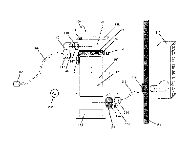
[0010] FIG. 1 illustrates a schematic of an exemplary evacuation system
according to an
embodiment of the present disclosure;
[0011] FIG. 2 illustrates an exemplary surgical apparatus according to an
embodiment of the
present disclosure;
[0012] FIG. 3 illustrates a cross sectional view of a portion of an exemplary
surgical apparatus;
[0013] FIG. 4 illustrates a schematic of an exemplary electrostatic
precipitator according to an
embodiment of the present disclosure;
[0014] FIG. 5 illustrates another schematic of an exemplary electrostatic
precipitator according to
an embodiment of the present disclosure;
[0015] FIG. 6 illustrates another schematic of an exemplary electrostatic
precipitator according to
an embodiment of the present disclosure;
[0016] FIG. 7 illustrates a schematic of an exemplary evacuation system
according to another
embodiment of the present disclosure;
[0017] FIG. 8 illustrates a schematic of an exemplary evacuation system
according to yet another
embodiment of the present disclosure;
[0018] FIG. 9 illustrates another schematic of an exemplary electrostatic
precipitator according to
an embodiment present disclosure;
[0019] FIG. 10 illustrates a flow diagram in accordance with a method and
apparatus for
performing exemplary embodiments of the present disclosure;
[0020] FIG. 11 illustrates another exemplary surgical apparatus according to
an embodiment of
the present disclosure; and
3
Date Recue/Date Received 2022-03-30
WO 2020/087007 PCT/US2019/058149
[0021] FIG. 12 illustrates another exemplary surgical apparatus according to
an embodiment of
the present disclosure.
[0022] FIG. 13 illustrates a top view of the collection cell 200 shown in FIG.
4
DETAILED DESCRIPTION OF THE INVENTION
[0023] It is to be understood that the invention may assume various
alternative orientations and
step sequences, except where expressly specified to the contrary. It is also
to be understood that
the specific assemblies and systems illustrated in the attached drawings and
described in the
following specification are simply exemplary embodiments of the inventive
concepts defined
herein Hence, specific dimensions, directions, or other physical
characteristics relating to the
embodiments disclosed are not to be considered as limiting, unless expressly
stated otherwise.
Also, although they may not be, like elements in various embodiments described
herein may be
commonly referred to with like reference numerals within this section of the
application. As used
in the following specification, terms of orientation such as "horizontal,"
"vertical," "left," "right,"
"up," and "down," as well as adjectival and adverbial derivatives thereof,
(e.g., "horizontally,"
"rightwardly," "upwardly," etc.), simply refer to the orientation of the
illustrated structure as the
particular drawing figure faces the reader. Similarly, the terms "inwardly"
and "outwardly"
generally refer to the orientation of a surface relative to its axis of
elongation, or of rotation, as
appropriate.
[0024] In view of the above, there remains a need for a fluid evacuation
system capable of
efficiently and effectively removing at least a portion of the surgical plume
created during surgery.
[0025] As illustrated in FIG. 1, in an embodiment, an evacuation system 100
(also referred to as a
fluid evacuation system) may comprise a surgical apparatus 102 in fluid
communication with an
electrostatic precipitator assembly 106 via a tube 104. A first end tube 104
may be in sealed
connection with a fitting 108 (shown in FIG 2) disposed at a proximal end of
the surgical apparatus
102 and a second end of the tube 104 may be in sealed connection with a fluid
inlet 110 of the
electrostatic precipitator assembly 106. It should be appreciated that
embodiments of tube 104
may be either removeably or fixedly attached forming a sealed connection with
fitting 108 and
fluid inlet 110. A second tube 112 may comprise a first end in sealed
connection with a fluid outlet
4
Date Recue/Date Received 2022-03-30
WO 2020/087007 PCT/US2019/058149
114 of the electrostatic precipitator assembly 106 and a second end in sealed
connection with a
fluid inlet 118 of a vacuum power source 116. Embodiments of second tube 112
include second
tube 112 being removeably or fixedly attached forming a sealed connection with
fluid inlet 118
and fluid outlet 114. In an embodiment, the vacuum power source 116 may be a
central vacuum
unit installed in a wall of medical facility or it may be a separate
standalone vacuum unit located
adjacent to or spaced from the electrostatic precipitator assembly 106. The
vacuum power source
116 is operable to create or urge a fluid flow through the surgical apparatus
102, the tube 104, the
electrostatic precipitator assembly 106, and the second tube 112.
[0026] As illustrated in FIGS. 2 and 3, in an embodiment, the surgical
apparatus 102 may include
an electrosurgical pencil having a cutting element 120 and a longitudinal axis
122. The surgical
apparatus 102 may also comprise a hollow body 124 enclosing a fluid conduit
126 (see FIG 3)
In an embodiment, the fluid conduit 126 may extend coaxially through the
longitudinal axis 122
of the electrosurgical pencil hollow body 124 from a distal end 128 to a
proximal end 130 thereof.
As illustrated in FIG. 2, the cutting element 120 may be disposed at the
distal end 128 of the
electrosurgical pencil hollow body 124.
[0027] Referring now to FIG. 2, in an embodiment, the cutting element 120 may
comprise at least
one electrode. The at least one electrode 120 may be employed to apply an
electrical current to a
patient's tissue for cutting and/or coagulation. In other embodiments, the
cutting element 120 may
comprise, but is not limited to, an ultrasonic scalpel or a laser scalpel.
[0028] As illustrated in FIG. 3, a port 132 may be disposed in the proximal
end 130 of the
electrosurgical pencil hollow body 124 in fluid communication with the fluid
conduit 126. In an
embodiment, the fitting 108 may comprise a barbed fitting having a fluid
conduit 134 disposed
therethrough. The fitting 108 is coupled with the electrosurgical pencil
proximal end 130 and is
in fluid communication with port 132. In other embodiments, the fitting 108
may comprise a
connector of other designs. For example, a female connector may be utilized in
place of the barbed
fitting 108. A female connector may be utilized to keep the inner diameter of
the fitting, and hence
the fluid conduit 134, as large as possible.
[0029] As illustrated in FIG 2, the electrosurgical pencil distal end 128 may
be provided with an
inlet 136 in fluid communication with the hollow body fluid conduit 126.
During operation of the
Date Recue/Date Received 2022-03-30
WO 2020/087007 PCT/US2019/058149
surgical apparatus 102, surgical smoke generated thereby enters the hollow
body inlet 136 and
passes through the hollow body fluid conduit 126 to the port 132. From the
port 132, surgical
smoke is communicated through the fitting 108 to the tube 104. Accordingly,
surgical smoke and
debris from a procedure may be conveyed through the surgical apparatus 102 to
the tube 104.
From the tube 104, the surgical smoke and debris are conveyed to the
electrostatic precipitator
assembly 106. The term surgical smoke may be referred to herein
interchangeably with the term
plume. It should be appreciated that while embodiments of the present
disclosure may be described
as being operable to evacuate fluid, smoke and/or plume, embodiments are also
operable to
evacuate gas, fluid, and/or particulates.
[0030] As illustrated in FIG. 2, in an embodiment, the surgical apparatus 102
may be provided with
a cut button 138 and a coagulate button 140 that provide different levels of
current to the cutting
element electrode 120. In one embodiment, the cut button 138 is operable to
activate the cutting
element electrode 120 at a first power level and the coagulate button 140 is
operable to activate the
cutting element electrode 120 at a second power level. In an embodiment, the
first power level may
be higher than the second power level. The cut button 138 and the coagulate
button 140 may also
be operable to activate the electrostatic precipitator assembly 106. In an
embodiment, activating
the surgical apparatus 102 also activates the electrostatic precipitator
assembly 106 at or about the
same time. Deactivating the surgical apparatus 102 may also deactivate the
electrostatic precipitator
assembly 106 at or about the same time. In an embodiment, the electrostatic
precipitator assembly
106 may maintain an activated state for a set period of time after the
surgical apparatus 102 is
deactivated and before the electrostatic precipitator assembly 106 itself
deactivates. It should be
appreciated that while FIGs. 2 and 3 illustrate a surgical apparatus 102 as an
electrosurgical device,
embodiments include surgical apparatus 102 being any type of medical device
used in a surgical
environment or medical environment in which fluid evacuation is required. For
instance,
embodiments of surgical apparatus 102 include a trocar, suction devices, and
the like.
[0031] As illustrated in FIG 11, in another embodiment of the fluid evacuation
system 100, the
surgical apparatus 102 may comprise a wand 102A. The wand 102A may comprise a
hollow
generally cylindrical body 124A defining a fluid conduit 126A therethrough. A
distal end 128A of
the wand 102A may be provided with an inlet 136A and a proximal end 130A of
the wand 102A
may be provided with an outlet 132A. The wand inlet 136A may be in fluid
communication with
6
Date Recue/Date Received 2022-03-30
WO 2020/087007 PCT/US2019/058149
the wand outlet 132A via the fluid conduit 126A therethrough. The proximal end
130A may be
connected with the tube 104 such that the wand outlet 132A is in fluid
communication with the
tube 104. The wand conduit 126A may include a constant or a variable diameter.
[0032] As illustrated in FIG. 12, in another embodiment of the fluid
evacuation system 100, the
surgical apparatus 102 may be a flexible tube 102B. The flexible tube 102B may
comprise a hollow
generally cylindrical body 124B defining a fluid conduit therethrough. A
distal end 128B of the
flexible tube 102B may be provided with an inlet 136B and a proximal end 130B
of the flexible
tube 102B may be provided with an outlet 132B. The flexible tube inlet 136B
may be in fluid
communication with the flexible tube outlet 132B via the fluid conduit
therethrough. The proximal
end 130B may be connected with the tube 104 such that the flexible tube outlet
132B is in fluid
communication with the tube 104. In another embodiment, the flexible tube
proximal end 130B
may be coupled directly with a manifold 142 or the electrostatic precipitator
assembly inlet 110.
The conduit through the flexible tube 102B may include a generally constant or
variable diameter.
[0033] In another embodiment, the surgical apparatus 102 may comprise a nozzle
defining a
variable cross-sectional area A removable sponge guard 103 (see FIG. 11) may
be located about
the distal end of the surgical apparatus 102 to prevent inadvertent suctioning
of dressings.
Embodiments of sponge guard 103 provide a porous flexible netting or covering
that is operable
to cover the inlet 136A such that larger objects (e.g., sponges, gauze, pads,
etc.) cannot enter the
fluid conduit 126A. Embodiments of sponge guard 103 are operable to allow
smoke, debris, and/or
particulates to pass through the plurality of holes 137A of sponge guard 103
so that the smoke,
debris, and/or particulates can enter fluid conduit 126A.
[0034] As illustrated in FIG. 1, in an embodiment, the manifold 142 may be
disposed in the fluid
path of the fluid evacuation system 100 between the tube 104 and the
electrostatic precipitator
assembly 106. The manifold 142 may be mounted to the fluid inlet 110 of the
electrostatic
precipitator assembly 106 such that the manifold 142 is in fluid communication
with the inlet 110.
The second end of the tube 104 may be coupled with an inlet of the manifold
142. In another
embodiment, the manifold 142 may be mounted internally to the electrostatic
precipitator assembly
106, such that the tube 104 is coupled directly with the fluid inlet 110 and
fluid outlet 110 is fluidly
coupled to manifold 142. The manifold 142 may include a fluid trap 143 for
capturing a portion
7
Date Recue/Date Received 2022-03-30
WO 2020/087007 PCT/US2019/058149
of the surgical smoke. The fluid trap 143 is operable to remove liquid such
as, but not limited to,
water from the surgical smoke. The manifold 142 may include a window for
viewing the level of
the liquid captured by the fluid trap 143. In an embodiment, the fluid trap
143 may comprise a
cold trap or a condenser.
[0035] In an embodiment, the manifold 142 may include a radio-frequency
identification tag 144
(RFID) operable to maintain and transmit identifying information of manifold
142 including make,
model, and/or status of manifold 142. The status of manifold 142 may include
the year manifold
142 was built, a length of time manifold 142 has been in use, and/or whether
the fluid trap 143
should be replaced because it is not functioning correctly or is not properly
filtering the fluid and
particulates that pass-through manifold 142. The electrostatic precipitator
assembly 106 may
include a RFID reader 146 capable of recognizing the RFID 144 of the manifold
142. The RFID
144 of the manifold 142 may be utilized to ensure component recognition such
that fluid
evacuation system 100 or electrostatic precipitator 106 only operates when the
electrostatic
precipitator RFID reader 146 recognizes the manifold 142 having the requisite
specifications,
make, model, status, and/or whether the fluid trap 143 should be replaced.
[0036] The electrostatic precipitator assembly 106 may further comprise a
housing 148, a hollow
conduit 161 and a valve 147 disposed within the housing 148 at the fluid inlet
110. The fluid inlet
110 and fluid outlet 114 are in fluid communication via the hollow conduit
161. The housing 148
may include the fluid inlet 110 and the fluid outlet 114. In an embodiment,
the valve 147 is in fluid
communication with fluid inlet 110 and may be operable to interrupt the flow
of surgical smoke, fluid,
and/or particulates through the electrostatic precipitator assembly 106 at or
adjacent to fluid inlet 110
during operation of the vacuum power source 116. As illustrated in FIG. 1, the
valve 147 may be located
within the electrostatic precipitator fluid inlet 110. In an embodiment, the
surgical apparatus 102 will
be able to operate valve 117. For instance, the cut button 138 and the
coagulate button 140 may be
operable to open and close the valve 147, such that when the surgical
apparatus 102 is activated the
valve 147 is open, and when the surgical apparatus 102 is deactivated the
valve 147 is closed In
other embodiments, the open and/or closed state of the valve 147 may be
operable by a keypad or
a button 149 disposed on or in the housing 148 such that the button 149 is
operable by medical staff
or a user. It should be appreciated that embodiments of valve 147 include
valve 147 being located
8
Date Recue/Date Received 2022-03-30
WO 2020/087007 PCT/US2019/058149
adjacent to or within outlet 114 such that valve 147 is operable to obstruct
or interrupt the flow of
surgical smoke, fluid, and/or particulates from entering tube 112.
[0037] The electrostatic precipitator assembly 106 may further comprise a
particulate filter 150
disposed within the housing 148 in hollow conduit 161. Filter 150 is located
downstream and is
fluidly connected to fluid inlet 110. The particulate filter 150 may capture
any coarse particulates
in the surgical smoke or flow of fluid through electrostatic precipitator
assembly 106 after entering
the electrostatic precipitator assembly 106. The particulate filter 150 is
replaceable and
removeable from electrostatic precipitator assembly 106 to ensure that
particulates accumulated in
the particulate filter 150 do not reduce the rate of fluid flow through the
electrostatic precipitator
assembly 106 below a predetermined threshold Embodiments include particulate
filter 150 having
an RFID tag 151 operable to maintain and transmit information such as the
make, model, status,
and/or filter rates of particulate filter 150 Embodiments further include
electrostatic precipitator
assembly 106 including an RFID reader 153 operable to communicate with RFID
tag 151 to read
the information maintained by RFID tag 151. RFID tag 151 and RFID reader 153
may be utilized
to ensure component recognition such that electrostatic precipitator 106
continues to operate and
filter within predetermined specifications.
[0038] With reference to FIG. 1, an electrostatic collection cell 200 may be
disposed within the
electrostatic precipitator assembly housing 148 in hollow conduit 161
downstream of the
particulate filter 150. The collection cell 200 comprises a collection surface
201. Embodiments
of the collection surface 201 include a planar or a plurality of planar
surfaces operable to be
electrically charged such that the collection surfaces 201 are oppositely from
an electrode 212
(shown in FIG. 4). An electrical power source 202 is electrically connected
with the collection
cell 200 to selectively supply electrical current to the collection cell 200.
In an embodiment, the
electrical power source 202 may be the alternating current (AC) power supply
of a building. In
another embodiment, the electrical power source 202 may be, but is not limited
to, a rechargeable
battery or a replaceable battery. In operation, the collection cell 200
induces an electrostatic charge
in at least a portion of the particulate suspended in the flow of fluid,
surgical smoke, and/or
particulates that pass-through electrostatic precipitator assembly 106. At
least a portion of the
charged particulate is then captured by the collection cell 200 such that the
particulates are
removed from the flow of fluid, surgical smoke, and/or particulates. The
electrostatic collection
9
Date Recue/Date Received 2022-03-30
WO 2020/087007 PCT/US2019/058149
cell 200 may comprise a one-stage design wherein the electrostatic charge is
induced relative to
the particulate collection site, or a two-stage design wherein the
electrostatic charge is induced in
the particulate upstream of the particulate collection site.
[0039] In an embodiment, the electrostatic precipitator assembly 106 may also
include a collection
tray 152 disposed underneath or adjacent to the collection cell 200 such that
collection tray 152
may collect, capture, and maintain particulates and other materials from
collection cell 200. The
collection tray 152 may accumulate particulate removed from the surgical
smoke, fluid, and/or
particulates by the collection cell 200 that is not maintained on or within
the collection cell 200 by
the electrostatic force therein. In other words, collection tray 152 is
operable to receive and
maintain accumulated particulate that does not stay on or within the
collection cell 200 because
the forces of gravity acting on the accumulated particulate are greater than
the electrostatic forces
of the collection cell 200, thus causing accumulated particulate to fall or be
removed from
collection cell 200. The collection tray 152 may be a removeable component,
such that when a
predeteimined amount of particulate accumulates within the collection tray
152, the collection tray
152 may be replaced. In another embodiment, the collection tray 152 may be
removeable such
that the collection tray 152 may be cleaned of particulate and reinstalled
within the electrostatic
precipitator assembly housing 148.
[0040] A second particulate filter 154 may be disposed within the housing 148
adjacent to the fluid
outlet 114. The second particulate filter 154 may capture any coarse
particulates in the surgical
smoke not removed by the collection cell 200 before they enter the tube 112.
The second
particulate filter 154 is replaceable to ensure that particulates accumulated
therein do not reduce
the rate of fluid flow through the electrostatic precipitator assembly 106
below a predetermined
threshold. In one embodiment the second particulate filter 154 is a High
Efficiency Particulate Air
filter. Embodiments include particulate filter 154 having an REID tag 155
operable to maintain
and transmit information such as the make, model, status, and/or filter rates
of particulate filter
154 Embodiments further include electrostatic precipitator assembly 106
including an REID
reader 157 operable to communicate with REID tag 154 to read the information
maintained by
RFID tag 155 REID tag 155 and RFID reader 157 may be utilized to ensure
component
recognition such that electrostatic precipitator 106 continues to operate and
filter within
predeteimined specifications.
Date Recue/Date Received 2022-03-30
WO 2020/087007 PCT/US2019/058149
[0041] In an embodiment, as illustrated in FIG. 4, the electrostatic
collection cell 200 may
comprise a plurality of hollow-cylindrical collection tubes 210. The
collection tubes 210 may be
disposed in two or more offset rows such that each row may be nested into an
adjacent row in a
generally honeycomb geometry. In an embodiment, not depicted, the collection
tubes 210 may
comprise a hollow hexagonal prismatic geometry. The longitudinal axes of the
collection tubes
210 may be generally vertically oriented. The electrostatic collection cell
200 may also include a
plurality of discharge electrodes 212. The discharge electrodes 212 may be
disposed generally
coaxially through the collection tubes 210. The discharge electrodes 212 are
in electrical
communication with the electrical power source 202 for electrically charging
particulate within
the surgical smoke.
[0042] In operation, surgical smoke, fluid, and/or particulates are
communicated through the
electrostatic precipitator assembly inlet 110 to hollow conduit 161, through
the particulate filter
150, then through the collection tubes 210 where the discharge electrodes 212
electrically charge,
or ionize, at least a portion of the remaining particulate in the surgical
smoke, fluid, and/or
particulates. Collection tubes 210 are oppositely charged from the discharge
electrodes 212 such
that the collection tubes 210 are operable to attract the particulate that is
electrically charged by
discharge electrodes 212. The ionized particulate is then accumulated on a
radially inner collection
surface of the collection tubes 210. Ionized particulate not accumulated on
the collection tubes 210
may be captured by the collection tray 152. After passing through the
collection cell 200, the
surgical smoke then passes through the second particulate filter 154 and out
the outlet 114.
[0043] The collection surface of the collection tubes 210 and the electrodes
212 can be oppositely
charged. In an embodiment, the power source 202 may be utilized to induce (i)
a negative voltage
in the discharge electrodes 212, and (ii) to induce a positive voltage in the
collection surface of the
collection tubes 210. In another embodiment, the power source 202 may be
utilized to induce a
negative voltage in the discharge electrodes 212. In this embodiment the
collection surface of the
collection tubes 210 may be connected to ground In still another embodiment,
the power source
202 may be utilized to induce a positive voltage in the discharge electrodes
212. In this
embodiment the collection surface of the collection tubes 210 may be connected
to ground or it
may have a negative voltage induced therein via the power source 202. In one
embodiment, the
electric potential difference between the discharge electrodes 212 and the
collection surface of the
11
Date Recue/Date Received 2022-03-30
WO 2020/087007 PCT/US2019/058149
collection tubes 210 is seven kilovolts ("7 kV"). The electric potential
difference between the
discharge electrodes 212 and the collection surface of the collection tubes
210 may be greater than
7 kV; however, undesirable electric arcing between the discharge electrodes
212 and the collection
surface may occur at a high enough electric potential difference.
[0044] In an embodiment, the collection tubes 210 may be temporarily removed
from the
electrostatic precipitator assembly housing 148 to be cleaned prior to
reinstallation. Alternatively,
or in conjunction with being cleanable, the collection tubes 210 may be
disposable and replaceable.
In embodiments where the collection surface of the collection tubes 210 are
not connected to
ground during operation, the opening of an access panel 213 in the housing 148
connects the
collection surface to ground. Connecting the collection surface to ground
prior to removal ensures
the prevention of harm to any person removing the collection tubes 210 from
the electrostatic
precipitator assembly 106 due to residual voltage in the collection surface.
[0045] In another embodiment, as illustrated in FIGs. 4 and 13, the
electrostatic precipitator
assembly 106 may include a cleaning element 300 to at least partially remove
the precipitate and
accumulated particulate from the collection surface of the collection cell
200. Referring to FIG.
13, shown is a top view of cleaning element 300 depicted in FIG. 4. The
cleaning element 300
may comprise a plurality of annular blades 302 located such that each blade
302 may move through
one of the collection tubes 210. In other words, each one of the collection of
tubes 210 will have
a corresponding annular blade 302 for removing accumulated particulate from
the radial interior
surface of the corresponding one of the collection of tubes 210. The radially
outer edge of the
blade 302 is disposed such that it will contact the collection surface 317 as
the blade 302 moves
through the collection tube 210. The collection surface 317 is located on the
radial interior surface
of collection tubes 210. Blades 302 are operable to move through the
longitudinal axis of
collection tubes 210 such that accumulated particulate is removed from
collection surface 317. In
an embodiment, the blade 302 may comprise an elastomeric material. One or more
apertures 304
may be disposed through the blade 302 to accommodate the discharge electrode
212 disposed
therethrough. Additionally, the blade 302 may be fixedly coupled with a first
shaft 306 capable
of linear actuation within the housing 148. An actuator assembly 310 may be
located within the
housing 148 to actuate the blade 302 through the collection tube 210. In an
embodiment, the
actuator assembly 310 may comprise a power source 312 such as a brushless
direct current (BLDC)
12
Date Recue/Date Received 2022-03-30
WO 2020/087007 PCT/US2019/058149
motor. The power source 312 may be coupled with a pinion gear 314 via a shaft
316. The pinion
gear 314 may be in meshed engagement with a plurality of teeth on the shaft
306. In other
embodiments, the actuator assembly 310 may comprise other linear actuators.
[0046] Actuation of the blade 302 through the collection tube 210 slides the
blade 302 along the
interior radial collection surface 317 of the collection tube 210 removing
particulate to the
collection tray 152. Blades 302 may be actuated through the other collection
tubes 210 via the
power source 312. In other embodiments, the additional blades 302 may be
actuated by additional
actuator assemblies 310. The actuator assembly 310 may be electrically
connected with a
controller 318. In an embodiment, the controller 318 may be in communication
with at least one
sensor 320 capable of detecting a change in the electrical charge of at least
one collection surface.
When the sensor 320 transmits a signal to the controller 318 indicating that
the electrical charge
of at least one collection surface has decreased below a predetermined voltage
(due to a build-up
of accumulated particulates on the collection surface shielding or reducing
the electrical charge),
the controller 318 operates the actuator assembly 310. In an embodiment, the
sensor 320 may
comprise a Hall-effect sensor. The sensor 320 may transmit signals to the
controller 318 via radio
wireless communication or a wired connection.
[0047] In another embodiment, as illustrated in FIG. 5, the electrostatic
collection cell 200 may
comprise a plurality of collection plates 220. The collection plates 220 may
be disposed generally
parallel to one another in a generally vertical plane. In this embodiment, the
electrostatic collection
cell 200 may also include a plurality of horizontally disposed discharge
electrodes 222 located
upstream of the collection plates 220. In operation, surgical smoke, fluid,
and/or particulates are
communicated through the electrostatic precipitator assembly inlet 110,
through the particulate
filter 150, then over and around the discharge electrodes 222 where at least a
portion of the
remaining particulate in the surgical smoke, fluid, and/or particulates are
electrically charged or
ionized. The surgical smoke, fluid, and/or particulates then pass between the
collection plates 220
where the ionized particulate is accumulated on a collection surface thereof.
Ionized particulate
not accumulated on the collection plates 220 may be captured by the collection
tray 152
Embodiments provide that collection tray 152 is located beneath collection
plates 220 such that
excess ionized particulate can fall through hollow conduit 161 on to
collection tray 152 after a
predeteimined amount of particulate accumulates on the surface of collection
plates 220. The
13
Date Recue/Date Received 2022-03-30
WO 2020/087007 PCT/US2019/058149
predetermined amount of accumulated particulate to cause additional ionized
particulate to fall
will occur when the amount of ionized particulate on the surface of collection
plates 220 is operable
to block additional ionized particulate from being attracted to collection
plates 220 such that the
forces of gravity are greater than the magnetic pull between ionized
particulate and the collection
plates 220. After passing through the collection cell 200, the surgical smoke
then passes through
the second particulate filter 154 and out the outlet 114.
[0048] The collection surface of the collection plates 220 and the discharge
electrodes 212 are
oppositely charged. In an embodiment, the power source 202 may be utilized to
induce a negative
voltage in the discharge electrodes 222 and to induce a positive voltage in
the collection surface
of the collection plates 220. In another embodiment, the power source 202 may
be utilized to
induce a negative voltage in the discharge electrodes 222, and the collection
surface of the
collection plates 220 may be connected to ground. In still another embodiment,
the power source
202 may be utilized to induce a positive voltage in the discharge electrodes
222, and the collection
surface of the collection plates 220 may be connected to ground or have a
negative voltage induced
therein via the power source 202. In one embodiment, the electric potential
difference between
the discharge electrodes 222 and the collection surface of the collection
plates 220 is seven
kilovolts ("7 kV"). The electric potential difference between the discharge
electrodes 222 and the
collection surface of the collection plates 220 may be greater than 7 kV;
however, undesirable
electric arcing between the discharge electrodes 222 and the collection
surface may occur at a high
enough electric potential difference.
[0049] In an embodiment, the collection plates 220 may be temporarily removed
from the
electrostatic precipitator assembly housing 148 to be cleaned prior to
reinstallation. Alternatively,
or in conjunction with being cleanable, the collection plates 220 may be
disposable and
replaceable. In embodiments where the collection surface of the collection
plates 220 is not
connected to ground during operation, the opening of an access panel 213 in
the housing 148
connects the collection surface to ground Connecting the collection surface to
ground prior to
removal ensures the prevention of harm to any person removing the collection
plates 220 from the
electrostatic precipitator assembly 106 due to residual voltage in the
collection surface.
14
Date Recue/Date Received 2022-03-30
WO 2020/087007 PCT/US2019/058149
[0050] Referring now to FIG. 6, in another embodiment, the electrostatic
precipitator assembly
106 may include a cleaning element 400 to at least partially remove the
precipitate and
accumulated particulate from the collection surface of the collection cell
200. The cleaning
element 400 may include a plurality of blades 402. Each of the blades 402 may
be disposed
between two of the plates 220 on an exterior planar surface of plates 220. The
blades 402 may be
made of an elastomeric material. The opposing edges of each blade 402 are in
contact with the
collection surfaces of the collection plates 220 during actuation of the
blades 402. The blades 402
may be coupled with a transversely disposed arm 404 operably coupled with an
actuation assembly
410.
[0051] The actuator assembly 410 may be electrically connected with a
controller 418. In an
embodiment, the controller 418 may be in communication with at least one
sensor 420 capable of
detecting a change in the electrical charge of at least one collection
surface. When the sensor 420
transmits a signal to the controller 418 indicating that the electrical charge
of at least one collection
surface has decreased below a predetermined voltage, the controller 418
operates the actuator
assembly 410 such that blades 402 are moved to remove accumulated particulate
from the surface
of plates 220. In an embodiment, the sensor 420 may comprise a Hall-effect
sensor. The sensor
420 may transmit signals to the controller 418 via radio wireless
communication or a wired
connection.
[0052] In an embodiment, the cleaning element 400 may include a nozzle 422
operable to spray fluid
onto the collection surface of the collection plates 220 to at least partially
remove precipitate therefrom
and into the collection tray 152. The nozzle 422 may be utilized independently
from the blades 402 or
in conjunction therewith. Nozzle 422 may be operably coupled to controller 418
such that controller
418 can activate or deactivate nozzle 422 to selectively spray fluid onto the
collection surface of the
collection plates 220.
[0053] As illustrated in FIG. 9, in another embodiment, the electrostatic
collection cell 200 may
comprise a plurality of coaxial hollow-cylindrical collection tubes 230. The
collection tubes 230
may comprise an outer collection tube with additional collection tubes
disposed coaxi ally and
radially within. The longitudinal axes of the collection tubes 230 may be
generally vertically
oriented. At least one of the discharge electrodes 212 may be disposed
generally coaxially through
Date Recue/Date Received 2022-03-30
WO 2020/087007 PCT/US2019/058149
the radially innermost collection tube 230, additional discharge electrodes
212 may be disposed
radially between the other collection tubes 230. The discharge electrodes 212
are in electrical
communication with the electrical power source 202 for electrically charging
particulate within
the surgical smoke.
[0054] The collection surface of the collection tubes 230 and the discharge
electrodes 212 are
oppositely charged. In an embodiment, the power source 202 may be utilized to
induce a negative
voltage in the discharge electrodes 212 and to induce a positive voltage in
the collection surface
of the collection tubes 230. In another embodiment, the power source 202 may
be utilized to
induce a negative voltage in the discharge electrodes 212, and the collection
surface of the
collection tubes 230 may be connected to ground. In still another embodiment,
the power source
202 may be utilized to induce a positive voltage in the discharge electrodes
212, and the collection
surface of the collection tubes 230 may be connected to ground or have a
negative voltage induced
therein via the power source 202. In one embodiment, the electric potential
difference between
the discharge electrodes 212 and the collection surface of the collection
tubes 230 is seven kilovolts
("7 kV"). The electric potential difference between the discharge electrodes
212 and the collection
surface of the collection tubes 230 may be greater than 7 kV, however,
undesirable electric arcing
between the discharge electrodes 212 and the collection surface may occur at a
high enough
electric potential difference.
[0055] In an embodiment, the collection tubes 230 may be temporarily removed
from the
electrostatic precipitator assembly housing 148 to be cleaned prior to
reinstallation. Alternatively,
or in conjunction with being cleanable, the collection tubes 230 may be
disposable and replaceable.
In embodiments where the collection surface of the collection tubes 230 is not
connected to ground
during operation, the opening of an access panel 213 in the housing 148
connects the collection
surface to ground. Connecting the collection surface to ground prior to
removal ensures the
prevention of harm to any person removing the collection tubes 230 from the
electrostatic
precipitator assembly 106 due to residual voltage in the collection surface
[0056] With continued reference to FIG 9, in another embodiment, the
electrostatic precipitator
assembly 106 may include a cleaning element 500 to at least partially remove
the precipitate and
accumulated particulate from the collection surface of the collection cell
200. The cleaning
16
Date Recue/Date Received 2022-03-30
WO 2020/087007 PCT/US2019/058149
element 500 may comprise an annular blade 502 located such that the blade 502
may move
between a radially outer collection surface and a radially inner collection
surface of the collection
tubes 230. The radially outer and radially inner edge of the blade 502 is
disposed such that it will
contact the collection surfaces as the blade descends through the collection
tubes 230. In an
embodiment, the blade 502 may comprise an elastomeric material. One or more
apertures 504
may be disposed through the blade 502 to accommodate discharge electrodes 212
disposed
therethrough. Additionally, the blade 502 may be fixedly coupled with a first
shaft 506 capable
of linear actuation within the housing 148. A second shaft 508 may be slidably
coupled with the
blade 502 to support the orientation of the blade 502 during actuation thereof
An actuator
assembly 510 may be located within the housing 148 to actuate the blade 502
through the collection
tubes 230. In an embodiment, the actuator assembly 510 may comprise a power
source 512 such
as a brushless direct current (BLDC) motor. The power source 512 may be
coupled with a pinion
gear 514 via a shaft 516. The pinion gear 514 may be in meshed engagement with
a plurality of
teeth on the shaft 506. In other embodiments, the actuator assembly 510 may
comprise other linear
actuators.
[0057] In another embodiment, the electrostatic collection cell 200 may
include a collection
surface comprising a mesh 402 (shown in FIG. 7). The mesh 402 may comprise a
screen, an open-,
cell metal foam, wire wool, or wire sponge. As described in the embodiments
above, the potential
difference between the discharge electrodes 212 and the collection surface
facilitates accumulation
of ionized particulate on the collection surface. The mesh 402 collection
surface attracts ionized
particulate from the surgical smoke while having minimal impact on the flow
rate through the fluid
evacuation system 100.
[0058] With reference now to FIG. 1, the electrostatic precipitator assembly
106 may be located
adjacent to the vacuum power source inlet 118. In this embodiment, the
electrostatic precipitator
assembly 106 may be moved around an operating area for the convenience of
medical staff or
users The electrostatic precipitator assembly 106 may comprise selectively
locking wheels 902
to increase the mobility of the electrostatic precipitator assembly 106. In
another embodiment, as
illustrated in FIG 7, the electrostatic precipitator assembly 106 may be
mounted on a wall 160 at
or adjacent to the vacuum power source inlet 118. In this embodiment, a second
tube 112 for fluid
communication between the electrostatic precipitator assembly fluid outlet 114
and the vacuum
17
Date Recue/Date Received 2022-03-30
WO 2020/087007 PCT/US2019/058149
power source 116 may be obviated. In yet another embodiment, as illustrated in
FIG. 8, at least a
portion of the electrostatic precipitator assembly 106 may be located within
the wall 160.
[0059] In an embodiment, the controller 318 may include a processor operating
under the control
of a set of programming instructions, which may also be referred to as
software. The controller
318 may also include a memory 319 in which programming instructions are stored
and a processor
321 (shown in FIG. 4). The memory 319 can also store identification codes and
collection surface
electrical charge records over a period of time. The controller 318 may output
signals to the
actuator assembly 310 to operate the cleaning element. The controller 318 may
also output signals
to a user interface 323 operable to interact with a user to indicate when the
collection surface
should be cleaned or replaced. The user interface 323 may be included as a
part of the electrostatic
precipitator assembly 106 or may be included in a freestanding device.
Embodiments provide that
a user is able to activate the electrostatic precipitator 106, surgical
apparatus 102, and/or vacuum
source 116 through user interface 323. Embodiments of user interface 323
include keypads, touch
screens, buttons, computer interfaces and the like.
[0060] In practice, embodiments of the present disclosure provide a vacuum
power source 116
operable to create or urge a flow of fluid from surgical apparatus 102 through
tube 104, fluid inlet
110, hollow conduit 161, filter 150, collection cell 200, collection tray 152,
fluid outlet 114, to
vacuum power source 116. Fluid and particulates that enter hollow conduit 161
flow to filter 150
such that larger particulates and smoke are filtered out of the flow of fluid
by filter 150. The flow
of fluid is then electrically charged by electrodes (e.g., 212, 222, etc.)
such that they are either
negatively or positively charged. The electrically charged flow of fluid then
passes through or
over collection cells (e.g., 200) wherein collection cells are oppositely
charged from that of the
electrodes. The passing flow of fluid is attracted towards and accumulates on
the collection cells.
Any remaining flow of fluid then passes over or adjacent to the collection
tray 152 and out of
electrostatic precipitator 106 to vacuum power source 116. In some
embodiments, collection cells
200 can be cleaned by cleaning elements 300 when the collection cells
accumulate enough charged
particulates such that they cannot attract anymore particulates. In other
embodiments, collection
cells 200 are removably affixed within electrostatic precipitator such that
they accumulated
particulates can be manually removed.
18
Date Recue/Date Received 2022-03-30
WO 2020/087007 PCT/US2019/058149
[0061] Reference is now made to FIG. 10, depicting a simplified logic flow
diagram in accordance
with an embodiment of a method of providing a fluid evacuation system. The
method begins at
block 1002 which states providing a surgical apparatus having a fluid conduit
therethrough;
providing a vacuum tube fluidly coupled with the surgical apparatus fluid
conduit; providing a
vacuum source fluidly coupled with the vacuum tube operable to create a fluid
flow; and providing
an electrostatic precipitator disposed in the fluid flow. Block 1004 then
indicates wherein the
electrostatic precipitator is operable to filter a plurality of particulates
from a plume without creating
resistance to the flow of the plume. Block 1006 states wherein a power source
is electrically coupled
with the electrostatic precipitator. Block 1008 relates wherein operating the
electrostatic precipitator
does not increase a noise level of the vacuum source, and block 1010 indicates
wherein operating the
electrostatic precipitator does not increase a power output of the vacuum
source.
[0062] The logic diagram of FIG. 10 may be considered to illustrate the
operation of a method, or a
result of execution of computer program instructions stored in a computer-
readable medium. The logic
diagram may also be considered a specific manner in which components of a
device are configured to
cause that device to operate.
[0063] It should be appreciated that while embodiments of electrostatic
precipitator assembly 106
described above have been described as having two particulate filters and an
electrostatic collector,
embodiments include electrostatic precipitator assembly 106 having one or zero
particulate filters.
[0064] One or more features of the embodiments described herein may be
combined to create
additional embodiments which are not depicted. While various embodiments have
been described
in detail above, it should be understood that they have been presented by way
of example, and not
limitation. It will be apparent to persons skilled in the relevant arts that
the disclosed subject matter
may be embodied in other specific forms, variations, and modifications without
departing from
the scope, spirit, or essential characteristics thereof The embodiments
described above are
therefore to be considered in all respects as illustrative, and not
restrictive. The scope of the
invention is indicated by the appended claims, and all changes that come
within the meaning and
range of equivalents thereof are intended to be embraced therein.
19
Date Recue/Date Received 2022-03-30