Note : Les descriptions sont présentées dans la langue officielle dans laquelle elles ont été soumises.
CA 03090902 2020-08-11
Des cription
AN ENVIRONMENTALLY FRIENDLY REMEDIATION METHOD AND
SYSTEM COMBINED WITH SOIL WASHING AND THERMAL DESORPTION FOR
TREATING HIGH-CONCENTRATION OIL SLUDGE
Technical Field
The present disclosure relates to the technical field of treating oil sludge,
and more
specifically to methods and systems for treating high-concentration oil sludge
from an
environmentally friendly remediation method and system combined with soil
washing and
thermal desorption.
B ackground Art
Oil is a chemical energy. During mining, transportation, storage and
processing for oil, a
large amount of waste residue, waste water and waste gas are inevitably
produced, which
poses a huge potential threat to the environment and human security. In
particular,
high-concentration oil sludge contains a large amount of odorous toxic
substances such as
benzene, hydrazine, phenols, and hydrazine. If the oil sludge is not treated
in time, it will
cause pollution in production area and surrounding environment. The
volatilization of volatile
compounds in oil sludge may cause the total hydrocarbon concentration to
exceed the
standard in the production area. The scattered and piled oil sludge will
influence the surface
water and even the groundwater, then COD, BOD, and total petroleum
hydrocarbons in the
water may exceed the standard. High concentration of crude oil in the oil
sludge can result in
exceeded total petroleum hydrocarbon in the soil, compacted soil, destroyed
vegetation,
degraded grassland, and influenced ecological environment. Because some
hydrocarbon
components in crude oil are carcinogenic, teratogenic, and mutagenic, oil
sludge in oil fields
has been classified as hazardous solid waste (HWO8) for management.
Generally, the oil sludge with oil content greater than 15% is called high-
concentration
oil sludge. At present, thermal chemical washing is normally used to treat
high-concentration
1
Date Recue/Date Received 2020-08-11
CA 03090902 2020-08-11
oil sludge for crude oil recovery. But if only applying the thermal chemical
washing method,
the residual high oil content in the treated oil sludge still does not meet
the criteria for direct
emissions or utili7ation. If direct-heating thermal desorption is used to
treat heavy oil sludge,
there are serious potential safety risks, and disadvantages such as high
energy consumption
and waste of petroleum resources.
Summary
To overcome shortcomings of the prior art, the present disclosure provides an
environmentally friendly remediation method and system combined with soil
washing and
thermal desorption to treat high-concentration sludge. Certain methods and
systems of this
invention disclose an innocuous approach for resource utili7ation of oil
sludge.
In order to achieve the above objectives, this disclosure includes the
following steps:
(1) Pretreatment for homogenization and impurity removal: conditioning and
dispersing
the oil sludge, and removing rubbish and sundries in the slurry.
(2) Thermal chemical washing treatment: the sludge after homogenization and
impurity
removal is sent to thermal chemical washing tank containing hot water and
washing agent,
then stirring separates the crude oil from the oil sludge, and the crude oil
in the top of the
thermal chemical washing tank is scraped out and stored in a recycle oil tank.
The solid phase
after thermal chemical washing is discharged from the bottom of the tank into
the
high-efficiency solid-liquid separator.
(3) Solid-liquid separation and oil-water separation: solid-liquid separation
is conducted
by high-efficiency solid-liquid separator. The oil content of the treated oil
sludge is reduced to
3%-6%, and the water content is to 60%-70%. Then the oil sludge is transported
to temporary
storage area, or directly sent to the sludge dryer. The sewage separated by
the high-efficiency
solid-liquid separator is sent to the oil-water separator, and the oil
separated by the oil-water
separator is sent to the oil recovery tank. The sewage separated by the oil-
water separator is
sent to the integrated treatment system for sewage treatment, then the treated
water is stored
2
Date Recue/Date Received 2020-08-11
CA 03090902 2020-08-11
in the water storage tank and recycled for thermal chemical washing tank.
(4) Oil sludge drying and condensing recovery treatment: the oil sludge sent
to the
sludge dryer is dried to a moisture content of less than 20%, and the steam
generated during
the drying process is sent to a condensate recovery system for condensation.
Condensed oil
and water in the condensate after condensation are sent to the oil-water
separator for oil-water
separation.
(5) Thermal desorption treatment and high-temperature combustion oxidation
treatment
for oil sludge: the oil sludge treated by the sludge dryer is sent to the
thermal desorption
system, and the temperature of the thermal desorption chamber which must have
a
micro-negative pressure is controlled at 300 C -750 C. Meanwhile, the
direction of oil sludge
transportation need to opposite to the direction of flue gas flow, and make
sure that the sludge
is desorbed and decomposed under oxygen-deficient condition.
(6) Heat exchange treatment: the flue gas generated in the thermal desorption
system in
the step (5) and the non-condensable light component produced in the
condensate recovery
system in the step (4) are sent to the high-temperature combustion oxidation
system for
complete combustion oxidation. The high-temperature exhaust gas from the high-
temperature
combustion oxidation system is sent to the waste heat boiler for waste heat
recycle, and the
generated superheated steam is used as a heat source for the thermal chemical
washing tank
and the sludge dryer.
(7) Cooling and dust removal treatment for exhaust gas: the medium-temperature
tail gas
from the waste heat boiler is sent to the quench tower. The temperature of
tail gas is reduced
to below 200 C through the quench tower, then the acid gas is removed by
cooling, dusting,
and spraying the alkali liquid. The treated tail gas met the standard is
discharged into the
atmosphere through the chimney.
In the step (6), the high-temperature combustion oxidation system is fired by
an open
flame of natural gas. The working temperature is in the range of 850 C-1100 C,
and the
3
Date Recue/Date Received 2020-08-11
CA 03090902 2020-08-11
residence time is 1.5 s- 2.0 s to ensure complete elimination of the organic
components to
prevent dioxin production.
In the step (6), the high-temperature exhaust gas produced from the high-
temperature
combustion oxidation system is about 1000 C, which is then lowered to a
medium-temperature exhaust gas of 500 C after being sent to a waste heat
boiler for waste
heat recycle.
The invention relates to an environmentally friendly method and system
combined with
soil washing and thermal desorption for high-concentration oil sludge, which
is mainly
composed of a thermal chemical washing system and a thermal desorption system.
The
thermal chemical washing system is composed of oil sludge homogenizing tank 1,
thermal
chemical washing tank 2, high-efficiency solid-liquid separator 3, oil-water
separator 4,
integrated treatment system for sewage treatment 6, and water storage tank 23
sequentially
connected by pipelines. The top oil outlet of the thermal chemical washing
tank 2 and the oil
outlet of the oil-water separator 4 are respectively connected to the oil
recovery tank 5. The
bottom of the thermal chemical washing tank 2 is connected to the high-
efficiency solid-liquid
separator 3, and the liquid outlet of the high-efficiency solid-liquid
separator 3 is connect with
oil-water separator 4. The thermal desorption system comprises an sludge dryer
10, a
condensate recovery system 11, thermal desorption feeding system 7, a thermal
desorption
system 8, a high-temperature combustion oxidation system 9, a waste heat
boiler 13, cooling
and dust removal treatment system for exhaust gas, and a discharge system. The
solid
discharge port of the high efficiency solid-liquid separator 3 is connected
with the feed port of
the sludge dryer 10, and the steam outlet of sludge dryer 10 is connected with
condensate
recovery system 11. The non-condensable gas outlet of the condensate recovery
system 11 is
connected to the high-temperature combustion oxidation system 9. The
condensate outlet of
the condensate recovery system 11 is connected to the oil-water separator 4.
The solid
discharge port of the sludge dryer 10 is connected with the thermal desorption
feeding system
4
Date Recue/Date Received 2020-08-11
CA 03090902 2020-08-11
7, and the thermal desorption feed system 7 is connected to the thermal
desorption system 8.
The thermal desorption flue gas outlet 83 of the thermal desorption system 8
is connected to
the flue gas inlet 91 of the high-temperature combustion oxidation system 9.
The discharge
port of the thermal desorption system 8 is connected to the discharge system,
and the exhaust
gas outlet 93 of the high-temperature combustion oxidation system 9 is
connected to the waste
heat boiler 13. The steam outlet of the waste heat boiler 13 is connected to
the thermal
chemical washing tank 2 and the sludge dryer 10. The tail gas outlet of the
waste heat boiler is
connected with the cooling and dust removal system for exhaust gas. The tail
gas is
discharged to the atmosphere after being treated by the cooling and dust
removal treatment
system.
The oil-water separator 4 of this disclosure is composed of a buffer tank 41,
a reaction
tank 42, an oil storage tank 44, and a water discharge tank 43. The buffer
tank 41, the reaction
tank 42, and the water discharge tank 43 are arranged in order. The oil
storage tank 44 is
located on the top of the reaction tank 42. The oil storage tank 44 is
connected to the oil
recovery tank 5, and the buffer tank 41 is connected to the liquid outlet of
the high-efficiency
solid-liquid separator 3.
The thermal desorption feeding system 7 of this disclosure is composed of a
feed silo 71,
a belt conveyor 72 and a metering feed hopper 73. The feed silo 71 is at the
inlet of the belt
conveyor 72, and the metering feed hopper 73 is at the outlet of the belt
conveyor 72. The
outlet of the metering feed hopper 73 is connected with the inlet of the
thermal desorption
system 8.
The thermal desorption system 8 of this disclosure comprises a refractory-
coated thermal
desorption chamber, a series of thermal desorption burners 82 mounted on top
of the thermal
desorption chamber, and a stainless steel crawler conveyor belt 81 below the
thermal
desorption burner 82. The thermal desorption chamber has a feeding inlet at
one end, a
discharge propeller 84 at the other end, and a thermal desorption flue gas
outlet 83 at the top.
Date Recue/Date Received 2020-08-11
CA 03090902 2020-08-11
The high-temperature combustion oxidation system 9 of this invention comprises
a
high-temperature combustion chamber. One end of the high-temperature
combustion chamber
is set with a flue gas inlet 91 and a high-temperature burner 92, and the
other end is provided
with a exhaust gas outlet 93 which is connected to the waste heat boiler 13.
The cooling and dust removal treatment system for exhaust gas of this
invention
comprises a quench tower 14, a spray tower 15, a settling tower 16, an induced
draft fan 17,
and a chimney 18. The spray tower 15 is connected with the settling tower 16,
and the quench
tower 14 is connected to the spray tower15. The outlet of the settling tower
16 is connected to
the chimney 18 with a pipe with the induced draft fan 17 mounted on.
The discharge system of this disclosure is composed of a discharge hopper 19,
a double
helix discharge machine 20, and a discharge silo 21. The discharge hopper 19
is located at the
inlet of the double helix discharge machine 20, and the discharge silo 21 is
located at the
outlet of the double helix discharge machine 20. The outer layer of the double
helix discharge
machine 20 is wrapped with a layer of cooling water. The top of the discharge
silo 21 set a
spraying device to reduce the temperature and dust of the dregs in the silo.
Compared with the prior art, this invention has the following advantages:
(1) The washing agent used in the invention is environmentally friendly, and
the washing
effect is remarkable. After being washed, the oil-water-solid three phase
stratified efficiency is
fast, and the oil recovery rate is high.
(2) The thermal desorption system of the invention adopts heat-resistant and
anti-corrosion stainless steel crawler conveyor belt for transmission, and
direct heat for
heating oil sludge. The thermal desorption system with high operating
temperature and
residence time, has high desorption efficiency and large processing capacity.
(3) The whole system of the invention is kept under the condition of micro-
negative
pressure. Normally, it can ensure that pollutants and dust do not overflow and
prevent
secondary pollution.
6
Date Recue/Date Received 2020-08-11
CA 03090902 2020-08-11
(4) The high-temperature combustion chamber has enough length, sufficient
residence
time, excess air added, and highly enough combustion temperature, to achieve
3T incineration
and ensure complete combustion of the organic gas to effectively prevent the
generation of
dioxins.
(5) Recycling the waste heat of the entire system saves energy and reduces
energy
consumption costs.
(6) The combination of thermal chemical washing technology and thermal
desorption
technology can achieve multiple functions of recycling petroleum resources and
heat, and oil
minimization and innocent treatment, simultaneously.
Brie fDes cription ofDrawings
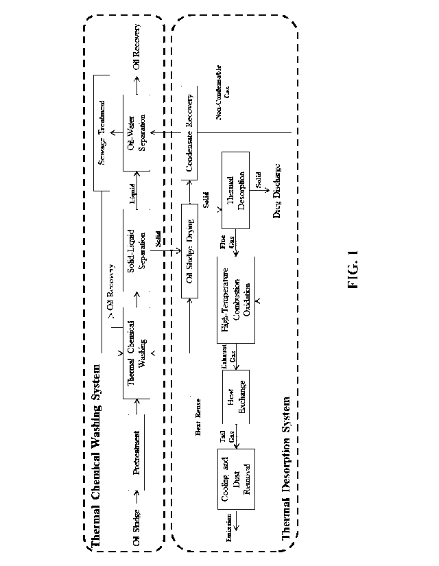
FIG 1 is a logic diagram of an environmentally friendly remediation system
combined
with soil washing and thermal desorption for treating high-concentration oil
sludge.
FIG 2 is a schematic process flow diagram of an environmentally friendly
remediation
system combined with soil washing and thermal desorption for treating high-
concentration oil
sludge.
In the appended drawings of FIGS: oil sludge homogenizing tank 1, thermal
chemical
washing tank 2, high efficiency solid-liquid separator 3, oil-water separator
4, sewage buffer
tank 41, reaction tank 42, oil storage tank 44, water discharge tank 43, oil
recovery tank 5,
integrated treatment system for sewage treatment 6, thermal desorption feeding
system 7, feed
silo 71, belt conveyor 72, metering feed hopper 73, thermal desorption system
8, stainless
steel crawler conveyor belt 81, thermal desorption burner 82, thermal
desorption flue gas
outlet 83, discharge propeller 84, high-temperature combustion oxidation
system 9, flue gas
inlet 91, high-temperature burner 92, exhaust gas outlet 93, sludge dryer 10,
condensate
recovery system 11, condensate pump 12, waste heat boiler 13, quench tower 14,
spray tower
15, settling tower 16, induced draft fan 17, chimney 18, discharge hopper 19,
double helix
discharge machine 20, discharge silo 21, dosing system 22, water storage tank
23 The first
7
Date Recue/Date Received 2020-08-11
CA 03090902 2020-08-11
sludge pump 24, the second sludge pump 25, the sewage pump 26, and the bar
screen 27.
Detailed Description
In the following description, numerous details are provided for an
understanding of this
invention with attached drawings.
As shown in the FIG 1, an environmentally friendly remediation system combined
with
soil washing and thermal desorption to treat high-concentration soil sludge of
this invention
comprises the following processing steps:
(1) Pretreatment for homogenization and impurity removal: the sludge is
tempered and
dispersed during the pretreatment. In the process of conditioning, dispersant
can be added to
adjust the dispersibility of the oil sludge. The rubbish and sundries
(fragments of color-strip
woven bag, labour protection appliance, weeds, bricks, wires) which are larger
than 10 mm
are intercepted by the grille, and the debris intercepted by the grille is
regularly cleaned.
(2) Thermal chemical washing treatment: the sludge after homogenization and
impurity
removal is sent into a thermal chemical washing tank containing hot water (60
C -80 C) and
washing agent (such as lye, surfactant). The thermal chemical washing tank is
equipped with
a dosing system for adding washing agent. The green washing agent, hot water,
and the oil
sludge are forcibly stirred by the stirring paddle in the tank, so that the
crude oil is separated
from the sludge. The separated oil in the top of the thermal chemical washing
tank is scraped
out and stored in an oil recovery tank. The solid phase after the thermal
chemical washing is
discharged from the bottom of the thermal chemical washing tank to the high-
efficiency
solid-liquid separator.
(3) Solid-liquid separation and oil-water separation: solid-liquid separation
is conducted
by high-efficiency solid-liquid separator. The oil content of the separated
sludge is reduced to
3%-6%, and the water content is 60%-70%. A small dump truck transfers
separated sludge to
the temporary storage area or directly to the sludge dryer for oil sludge. The
sewage separated
by the high-efficiency solid-liquid separator is sent to the oil-water
separator, and the oil
8
Date Recue/Date Received 2020-08-11
CA 03090902 2020-08-11
separated by the oil-water separator is sent into the oil recovery tank. Then
the sewage
separated by the oil-water separator is sent to the integrated treatment
system for sewage
treatment (the structure of this equipment can use the equipment named
"complete processing
equipment for heavy metal wastewater" disclosed by Chinese Patent No.
ZL201220225085. X,
and other appropriate sewage treatment equipment). The treated water is stored
in a water
storage tank and recycled for thermal chemical washing tank.
(4) Oil sludge drying and condensing recovery treatment: The moisture content
for
sludge after dewatering is about 60%, and this kind of sludge cannot directly
enter the thermal
desorption system. Therefore, the moisture content for sludge should be
reduced to below
20% in the sludge dryer. The heat source of the sludge dryer mainly comes from
the heat
recovered by the electric and waste heat boilers. The steam generated during
the drying
process is sent to the condensate recovery system for condensation. After the
oil and water are
condensed, the condensate is sent to the oil-water separator for oil-water
separation. The
recovered oil is collected and transported to the treatment station for
further treatment. The
separated water enters the integrated treatment system for sewage treatment,
then is reused for
the thermal chemical washing tank for the oil sludge. The non-condensable
light component
(non-condensable gas) is transported to the high-temperature combustion
oxidation system for
complete combustion oxidation to ensure that the flue gas is fully purified.
(5) Thermal desorption treatment and high-temperature combustion oxidation
treatment
for oil sludge: the oil sludge treated by the sludge dryer is sent to the
thermal desorption
system through the feeding system, and the continuous feeding of the sludge
makes the feed
port form a "soil stopper". This stopper can reduce the amount of air entering
the thermal
desorption system, effectively block the thermal desorption system from the
atmosphere, and
ensure that the thermal desorption chamber is kept at a state of micro-
negative pressure. The
sludge is transported through the stainless steel track in the thermal
desorption chamber. The
flow of oil sludge transportation is opposite to the direction of the flue gas
flow. During the
9
Date Recue/Date Received 2020-08-11
CA 03090902 2020-08-11
transportation, the sludge is heated by a series of thermal desorption burners
at the top of the
thermal desorption system, the amount of air entering is strictly controlled
to ensure that the
oil sludge is desorbed and decomposed in the absence of oxygen. Depending on
the type of oil
sludge and the moisture content of oil sludge, the temperature of the thermal
desorption
chamber can be set between 300 C and 750 C to ensure complete desorption of
the various
hydrocarbon fractions in the oil sludge. The flue gas generated from the
thermal desorption
system enters the high-temperature combustion oxidation system. The high-
temperature
combustion oxidation system uses natural gas as open flame for combustion. The
working
temperature is set in the range of 850 C-1100 C, and the set residence time is
ranging
1.5s-2.0s to ensure that organic components such as petroleum hydrocarbons in
the
non-condensable gas are completely and harmlessly eliminated, and prevent the
production of
dioxins.
(6) Heat exchange treatment: the flue gas generated in the thermal desorption
system in
the step (5) and the non-condensable light component produced in the
condensate recovery
system in the step (4) are sent to the high-temperature combustion oxidation
system for
complete combustion oxidation. Then, the high-temperature exhaust gas from the
high-temperature combustion oxidation system is sent to the waste heat boiler
for waste heat
recovery, then becomes a medium-temperature exhaust gas at 500 C. Meanwhile,
the
generated superheated steam is used as a heat source for the thermal chemical
washing tank
and the sludge dryer.
(7) Cooling and dust removal treatment for exhaust gas: the medium-temperature
tail
gasfrom the waste heat boiler is sent to the quench tower in which the
temperature of the tail
gas is reduced from 500 C to below 200 C in is, to avoid the regeneration of
dioxins. Then
the dust is removed, and the lye is sprayed to remove the acid gas. The
treated tail gas met the
standard is discharged to the atmosphere through the chimney.
Date Recue/Date Received 2020-08-11
CA 03090902 2020-08-11
The structure of the processing system used to implement the above methods is
shown in
FIG 2:
The whole system of the invention comprises two parts: a thermal chemical
washing
system for oil sludge and a thermal desorption system for oil sludge.
The thermal chemical washing system is composed of an oil sludge
homogenization tank
1, a thermal chemical washing tank 2, a high-efficiency solid-liquid separator
3, an oil-water
separator 4, an integrated treatment system for sewage treatment 6, and a
water storage tank
23 sequentially connected by pipelines. The oil sludge homogenization tank 1
has a bar screen
27, and the discharge port of the oil sludge homogenization tank 1 is
connected to the inlet of
the thermal chemical washing tank 2 through the first sludge pump 24. The
thermal chemical
washing tank 2 has an impeller and a dosing system 22 for washing agent. The
top oil outlet
of the thermal chemical washing tank 2 is connected to the oil recovery tank
5, and the bottom
discharge port of the thermal chemical washing tank 2 is connected to the
inlet of the
high-efficiency solid-liquid separator 3 through the second sludge pump 25.
The solid
discharge port of the high-efficiency solid-liquid separator 3 is connected to
the feed port of
the sludge dryer 10, and the liquid outlet of the high-efficiency solid-liquid
separator 3 is
connected with the inlet of the oil-water separator 4 through the sewage pump
26. The water
outlet of the oil-water separator 4 is connected to the water inlet of the
integrated treatment
system for sewage treatment 6, and the water outlet of the integrated
treatment system for
sewage treatment 6 is connected with the inlet of the water storage tank 23.
The water in the
water storage tank 23 is eventually returned to the thermal chemical washing
tank 2 for reuse.
The thermal desorption system for oil sludge comprises a sludge dryer 10, a
condensate
recovery system 11, a thermal desorption feeding system 7, a thermal
desorption system 8, a
high-temperature combustion oxidation system 9, a waste heat boiler 13, a
cooling and dust
removal treatment system for exhaust gas, and a discharge system. The steam
outlet of the
sludge dryer 10 is connected to the condensate recovery system 11, and the non-
condensable
11
Date Recue/Date Received 2020-08-11
CA 03090902 2020-08-11
gas outlet of the condensate recovery system 11 is connected to the high-
temperature
combustion oxidation system 9 for recycling. The condensate outlet of the
condensate
recovery system 11 is connected to the oil-water separator 4 via a pipeline
equipped with a
condensate pump 12. The solid discharge port of the sludge dryer 10 is
connected to the
thermal desorption feeding system 7. The thermal desorption feeding system 7
includes a feed
silo 71, a belt conveyor 72, and a metering feed hopper 73. The feed silo 71
is located at the
inlet end of the belt conveyor 72, and the metering feed hopper 73 is located
at the outlet end
of the belt conveyor 72. The feed silo 71 is connected to the solid discharge
port of the sludge
dryer 10, and the metering feed hopper 73 of the thermal desorption feed
system 7 is installed
at the inlet of the thermal desorption system 8. The thermal desorption system
8 includes a
refractory-coated thermal desorption chamber, a series of thermal desorption
burners 82
arranged on both sides of the center line of the top of thermal desorption,
and a stainless steel
crawler conveyor belt 81 under the thermal desorption burners 82. The thermal
desorption
chamber has feeding port at one end, a discharge propeller 84 at the other
end. A thermal
desorption flue gas outlet 83 is set at the top of the thermal desorption
chamber. A discharge
propeller 84 is connected to the discharge system. The mentioned discharge
system is
composed of a discharge hopper 19, a double helix discharge machine 20, and a
discharge silo
21. The discharge hopper 19 is located at inlet of the double helix discharge
machine 20. The
discharge silo 21 is located at the outlet of the double helix discharge
machine 20. The outer
layer of the double helix discharge machine 20 is covered with a layer of
cooling water, and a
spray device is arranged on the top of the discharge silo 21 to reduce the
temperature and dust
of the dregs in the silo. The thermal desorption flue gas outlet 83 is
connected with the
exhaust gas inlet 91 of the high-temperature combustion oxidation system 9.
The
high-temperature combustion oxidation system 9 comprises a high-temperature
combustion
chamber. The high-temperature combustion chamber is horizontally installed and
coated with
refractory material inside. One end of the high temperature combustion chamber
is and set
12
Date Recue/Date Received 2020-08-11
CA 03090902 2020-08-11
with a flue gas inlet 91 and a high-temperature burner 92, and the other end
has an exhaust
gas outlet 93 connected to the waste heat boiler 13. The heat source outlet of
the waste heat
boiler 13 is connected to the thermal chemical washing tank 2 and the sludge
dryer 10. The
tail gas outlet of the waste heat boiler is connected with the cooling and
dust removal
treatment system for exhaust gas. The tail gas is discharged to the atmosphere
after being
treated by the cooling and dust removal treatment system for exhaust gas.
The oil-water separator 4 of this invention is composed of a buffer tank 41, a
reaction
tank 42, an oil storage tank 44, and a water discharge tank 43. The buffer
tank 41, the reaction
tank 42, and the water discharge tank 43 are arranged in order. The oil
storage tank 44 is
located on the top of the reaction tank 42. The oil storage tank 44 is
connected to the oil
recovery tank 5, and the buffer tank 41 is connected to the liquid outlet of
the high-efficiency
solid-liquid separator 3.
The cooling and dust removal treatment system for exhaust gas of this
invention
comprises a quench tower 14, a spray tower 15, a settling tower 16, an induced
draft fan 17,
and a chimney 18. The spray tower 15 is connected with the settling tower 16,
and the quench
tower 14 is connected to the spray tower 15. The outlet of the settling tower
16 is connected to
the chimney 18 via a pipeline installed the induced draft fan 17. The treated
exhaust gas is
eventually discharged in the atmosphere through the chimney 18 with the help
of the induced
draft fan 17, after meeting the standard for emission.
The metering feed hopper 73 of the thermal desorption feeding system 7 of this
invention
adopts a double helix feeding mode, and forms a soil stopper through the
bottom reduction
design to reduce the entry of outside air into the thermal desorption system
8.
The working process of the processing system of this invention is as follows:
The oil sludge is sent to the oil sludge homogenizing tank 1, and the bar
screen 27 is
installed at the water outlet of the oil sludge homogenizing tank 1. During
the conditioning
process, the dispersant may be added to adjust the dispersibility of the oil
sludge. So rubbish
13
Date Recue/Date Received 2020-08-11
CA 03090902 2020-08-11
and sundries (fragments of color-strip woven bag, labour protection appliance,
weeds, bricks,
wires) which are larger than 10 mm are intercepted by the grille, and the
debris intercepted by
the grille is regularly cleaned.
The oil sludge after pretreatment is pumped into the thermal chemical washing
tank 2 by
the first sludge pump 24. The thermal chemical washing tank 2 is equipped with
a dosing
system 22. The stirring paddle in the tank is used to fully agitate the green
washing agent, hot
water, and the oil sludge, to separate the crude oil from the oil sludge. The
separated oil is
scraped from the top of the thermal chemical washing tank 2 and is stored in
the oil recovery
tank 5. The solid phase after thermal chemical washing enters the high-
efficiency solid-liquid
separator 3 from the bottom of thermal chemical washing tank 2 by the second
sludge pump
25.
The oil content of the oil sludge separated by the high-efficiency solid-
liquid separator 3
is reduced to 3%-6%, and the water content is 60%-70%. A small dump truck
transfers
separated sludge to the temporary storage area or directly to the sludge dryer
10. The sewage
separated by the high-efficiency solid-liquid separator 3 is sent to the oil-
water separator 4 by
the sewage pump 26. Then the sewage first enters the sewage buffer tank 41,
and flows into
the reaction tank 42 for aeration to separate the oil and water. The separated
oil flows into the
oil storage tank 44, and the separated water enters the integrated treatment
system for sewage
treatment 6 through the water discharge tank 43. The treated water is stored
in a water storage
tank 23 and recycled for thermal chemical washing tank 2.
The moisture content for sludge after dewatering is too high to directly enter
the thermal
desorption system, so it needs to be dried in the sludge dryer 10 to reduce
the moisture
content to less than 20%. The heat source of the sludge dryer 10 mainly comes
from the heat
recovered by the industrial electricity and the waste heat boiler 13. The
steam generated in the
drying process enters the condensate recovery system 11 for condensation, and
the oil and
water are condensed. Then the condensate enters the oil-water separator 4. The
recovered oil
14
Date Recue/Date Received 2020-08-11
CA 03090902 2020-08-11
enters the oil recovery tank 5 and is transported to the treatment station for
treatment. The
water separated by the oil-water separator 4 enters the integrated treatment
system for sewage
treatment 6 for reuse in the thermal chemical washing tank 2. The non-
condensable light
component (non-condensable gas) is delivered to the high-temperature burner 92
of the
high-temperature combustion oxidation system 9 for complete combustion
oxidation to ensure
that the flue gas is sufficiently purified.
The oil sludge which has been dried by the sludge dryer 10 is sent to the
metering feed
hopper 73 at the top of the thermal desorption system 8 through the thermal
desorption
feeding system 7. The oil sludge forms a "soil stopper" in the metering feed
hopper 73. This
stopper can reduce the amount of air entering the thermal desorption system 8
and effectively
block the thermal desorption system 8 from the atmosphere, and ensure that the
thermal
desorption chamber is kept at a state of micro-negative pressure. The sludge
is transported
through the stainless steel crawler conveyor belt 81 in the thermal desorption
chamber. The
flow of oil sludge transportation is opposite to the direction of the flue gas
flow. During the
transportation, the sludge is heated by a series of thermal desorption burners
82 at the top of
the thermal desorption system, and the amount of air entering is strictly
controlled to ensure
that the oil sludge is desorbed and decomposed in the absence of oxygen.
The 1000 C high-temperature exhaust gas from the high-temperature combustion
oxidation system 9 is sent to the waste heat boiler 13 for waste heat
recovery, and the
generated superheated steam is used as a heat source for the thermal chemical
washing tank 2
and the sludge dryer 10. The temperature of the exhaust gas recovered by the
waste heat
boiler 13 is reduced to 500 C or less. The heat is fully recovered, and the
dioxin regeneration
is avoided. The medium-temperature tail gas from the waste heat boiler is sent
to the quench
tower 14 in which the temperature of the tail gas is reduced from 500 C to
below 200 C in is,
to avoid the generation of dioxins. The cooled tail gas enters the spray tower
15 and the
settling tower 16 again. The dust is removed, and the lye is sprayed to remove
the acid gas.
Date Recue/Date Received 2020-08-11
CA 03090902 2020-08-11
The treated tail gas met the standard is discharged to the atmosphere through
the chimney.
The dreg treated by the thermal desorption system 8 is dropped onto the
discharge
hopper 19 by the discharge propeller 84, and then transported to the discharge
silo 21 for
storage by the double helix discharge machine 20. The outer layer of the
double helix
discharge machine 20 is covered with a layer of cooling water to prevent that
the high
discharge temperature affects the service life of the equipment. The discharge
silo 21 is sealed,
and the top of the discharge silo has a sprinkler to reduce the temperature
and dust for the
dregs in the silo.
Application examples of this invention:
Example 1:
Taking the tank-bottom oil sludge of an oilfield as the treatment object, the
moisture
content was 50%; the oil content was 18%; the average particle size was less
than 5mm. After
conditioning, oil sludge entered the thermal chemical washing tank, and the
recovery rate of
crude oil after washing was 66.7%. After the treatment by the high-efficiency
solid-liquid
separator, the moisture content for oil sludge was 65%, and the oil content
was reduced to 6%.
After drying, the moisture content for oil sludge was reduced to 20%, and the
dried oil sludge
was sent to the metering feeding hopper by the thermal desorption feeding
system. Then the
oil sludge dropped on the stainless steel crawler conveyor belt in the thermal
desorption
system. The temperature of the thermal desorption chamber was controlled
within the range
of 500 C ¨700 C, and the residence time was 20min. The temperature of the
high-temperature combustion oxidation chamber was controlled at 1100 C, and
the residence
time was 2s. The oil content of the dreg after thermal desorption was 220
mg/kg, and the
removal rate was 99.69%. The dioxin content of the high-concentration tail gas
after
purification by high-temperature oxidation combustion was less than
0.1TEQng/Nm3, and the
tail gas after treatment reached the emission standards.
16
Date Recue/Date Received 2020-08-11
CA 03090902 2020-08-11
Example 2:
Taking the oil sludge of an oilfield as the treatment object, the moisture
content was 40%;
the oil content was 15%; the average particle size was less than lOmm. After
conditioning, oil
sludge entered the thermal chemical washing tank, and the recovery rate of
crude oil after
washing was 80%. After the treatment by the high-efficiency solid-liquid
separator, the
moisture content for oil sludge was 60%-65%, and the oil content was reduced
to 3%. After
drying, the moisture content for oil sludge was reduced to 19%, and the dried
oil sludge was
sent to the metering feeding hopper by the thermal desorption feeding system.
Then the oil
sludge dropped on the stainless steel crawler conveyor belt in the thermal
desorption system.
The temperature of the thermal desorption chamber was controlled within the
range of 300 C
¨500 C, and the residence time was 18min. The temperature of the high-
temperature
combustion oxidation chamber was controlled at 850 C, and the residence time
was 1.5s. The
oil content of the dreg after thermal desorption was 200 mg/kg, and the
removal rate was
99.62%. The dioxin content of the high-concentration tail gas after
purification by
high-temperature oxidation combustion was less than 0.1TEQng/Nm3, and the tail
gas after
treatment reached the emission standards.
Example 3:
Taking the oil sand of an oilfield as the treatment object, the moisture
content was 55%;
the oil content was 25%; the average particle size was less than lOmm. After
conditioning, oil
sludge entered the thermal chemical washing tank, and the recovery rate of
crude oil after
washing was 80%. After the treatment by the high-efficiency solid-liquid
separator, the
moisture content for oil sludge was 60%-65%, and the oil content was reduced
to 5%. After
drying, the moisture content for oil sludge was reduced to 18%, and the dried
oil sludge was
sent to the metering feeding hopper by the thermal desorption feeding system.
Then the oil
sludge dropped on the stainless steel crawler conveyor belt in the thermal
desorption system.
The temperature of the thermal desorption chamber was controlled within the
range of 400 C
17
Date Recue/Date Received 2020-08-11
CA 03090902 2020-08-11
¨550 C, and the residence time was 20min. The temperature of the high-
temperature
combustion oxidation chamber was controlled at 950 C, and the residence time
was 1.8s. The
oil content of the dreg after thermal desorption was 180 mg/kg, and the
removal rate was
99.71%. The dioxin content of the high-concentration tail gas after
purification by
high-temperature oxidation combustion was less than 0.1TEQng/Nm3, and the tail
gas after
treatment reached the emission standards.
18
Date Recue/Date Received 2020-08-11