Sélection de la langue

Search

Sommaire du brevet 3098029 

Énoncé de désistement de responsabilité concernant l'information provenant de tiers

Une partie des informations de ce site Web a été fournie par des sources externes. Le gouvernement du Canada n'assume aucune responsabilité concernant la précision, l'actualité ou la fiabilité des informations fournies par les sources externes. Les utilisateurs qui désirent employer cette information devraient consulter directement la source des informations. Le contenu fourni par les sources externes n'est pas assujetti aux exigences sur les langues officielles, la protection des renseignements personnels et l'accessibilité.

Disponibilité de l'Abrégé et des Revendications

L'apparition de différences dans le texte et l'image des Revendications et de l'Abrégé dépend du moment auquel le document est publié. Les textes des Revendications et de l'Abrégé sont affichés :

  • lorsque la demande peut être examinée par le public;
  • lorsque le brevet est émis (délivrance).
(12) Demande de brevet: (11) CA 3098029
(54) Titre français: MECANISME DE DETENTE DE REGLAGE DE LA RESISTANCE
(54) Titre anglais: TRIGGER RESISTANCE SETTING MECHANISM
Statut: Examen
Données bibliographiques
(51) Classification internationale des brevets (CIB):
  • F41A 19/10 (2006.01)
  • F41A 19/16 (2006.01)
(72) Inventeurs :
  • MALINA, JAROSLAV (Tchéquie)
(73) Titulaires :
  • CESKA ZBROJOVKA A.S.
(71) Demandeurs :
  • CESKA ZBROJOVKA A.S. (Tchéquie)
(74) Agent: NORTON ROSE FULBRIGHT CANADA LLP/S.E.N.C.R.L., S.R.L.
(74) Co-agent:
(45) Délivré:
(22) Date de dépôt: 2020-11-03
(41) Mise à la disponibilité du public: 2021-06-06
Requête d'examen: 2022-10-24
Licence disponible: S.O.
Cédé au domaine public: S.O.
(25) Langue des documents déposés: Anglais

Traité de coopération en matière de brevets (PCT): Non

(30) Données de priorité de la demande:
Numéro de la demande Pays / territoire Date
PV2019-748 (Tchéquie) 2019-12-06

Abrégés

Abrégé anglais


8
ABSTACT
A trigger resistance mechanism, especially of rifles, comprising a trigger
device,
containing at least one class 1 lever (12) whose one arm is adapted to be
controlled by the trigger (2) while a trigger (2) resistance spring (4) bears
on the
other arm. The spring (4) is fitted, at the end averted from the trigger (2),
with a
bearing element (3) that bears on a cam (1) that is seated in the firearm
frame in
a rotary way.
Fig. 1
Date Recue/Date Received 2020-11-03

Revendications

Note : Les revendications sont présentées dans la langue officielle dans laquelle elles ont été soumises.


7
CLAIMS
1. A trigger resistance mechanism, especially of rifles, comprising a trigger
device, containing at least one class 1 lever (12) whose one arm is adapted to
be
controlled by the trigger (2) while a trigger (2) resistance spring (4) bears
on the
other arm, characterized in that the spring (4) is fitted, at the end averted
from
the trigger (2), with a bearing element (3) that bears on a cam (1) that is
seated
in the firearm frame in a rotary way.
2. The mechanism according to claim 1, characterized in that the cam (1) has
recesses (9) arranged along its perimeter that have different depths for
engagement of the bearing element (3).
3. The mechanism according to claim 2, characterized in that the cam (1) is
arranged on a shaft (10) wherein the shaft (10) is seated in a rotary way in a
bushing (5) that is mounted in the firearm frame.
4. The mechanism according to claim 3, characterized in that the bushing (5)
is
mounted in the firearm frame adjustably in the spring (4) axis direction.
5. The mechanism according to claim 4, characterized in that the bushing (5)
is
mounted in the firearm frame in a swiveling way on a transversal pin (6) so
that
the cam (1) is adjustable in the spring (4) axis direction.
6. The mechanism according to any of claims 3, 4 or 5, characterized in that
the shaft (10) is freely accessible in the firearm frame at the end that is
averted
from the cam (1) and is fitted with a shaped opening (11) for engagement of a
setting tool.
7. The mechanism according to any of claims 3, 4, 5 or 6, characterized in
that
a setscrew (7) bears on the bushing (5) to readjust the bushing (5) with the
cam
(1) in the spring (4) axis direction.
Date Recue/Date Received 2020-11-03

Description

Note : Les descriptions sont présentées dans la langue officielle dans laquelle elles ont été soumises.

1
TRIGGER RESISTANCE SETTING MECHANISM
Technical field
The invention relates to a trigger resistance setting mechanism, especially of
rifles, comprising a trigger device containing at least one class 1 lever
whose one
arm is adapted to be controlled by the trigger while the trigger resistance
spring
bears on its other arm.
Prior Art
Trigger resistance refers to the amount of force that needs to be exerted on
the
trigger to push it a consequently cause a shot.
is Conventional methods generally use a screw to set the trigger resistance
wherein the screw compresses or releases a spring acting directly on the
trigger.
In hunting weapons, these screws are mostly hidden inside the weapon, so to
set the trigger resistance, the stock must be removed. In sports weapons,
these
screws are generally situated around the trigger. A disadvantage of these
solutions is also the impossibility to control the actual trigger resistance
value. If
a screw gets excessively released, there is also a risk that it may fall out
and get
lost.
The document U52009113777 discloses a trigger assembly comprising a trigger
and a return spring plunger with a return spring wherein this assembly allows
the
user to reduce the pressure exerted on the trigger required for shooting from
a
firearm by allowing him to retract the return spring plunger to return it to
its initial
position, namely by inserting a lever that exerts force on the return spring
plunger
to move it away from the trigger. A disadvantage of such a solution is its
structural
complexity.
Date Recue/Date Received 2020-11-03

2
The object of the invention is to propose such a trigger resistance setting
mechanism that would not exhibit the above-mentioned drawbacks of the prior
art.
Disclosure of invention
The said object is achieved through a trigger resistance mechanism, especially
of rifles, comprising a trigger device, containing at least one class 1 lever
whose
one arm is adapted to be controlled by the trigger while a trigger resistance
io spring bears on the other arm, according to the invention the principle
of which is
that the spring is fitted, at the end averted from the trigger, with a bearing
element that bears on a cam that is seated in the firearm frame in a rotary
way.
An advantage of the mechanism according to the invention is quick and precise
is setting of the trigger resistance value. A change of the setting is
simple and does
not require any further handling of the weapon, e.g. removing the stock. The
design of the mechanism allows the user to easily check the set value any
time.
In a preferred embodiment, the cam has recesses with a variable depth arranged
20 along its perimeter for engagement of the bearing element.
In another preferred embodiment, the cam is arranged on a shaft wherein the
shaft is seated in a bushing in a rotary manner while the bushing is seated in
the
firearm frame.
To compensate production tolerances, the bushing is preferably seated in the
firearm frame adjustably in the spring axis direction, e.g. the bushing may be
seated in the firearm frame in a swiveling way on a transversal pin in such a
way
that the cam is adjustable in the spring axis direction, and a setscrew may
bear
on the bushing to move the bushing with the cam in the spring axis direction.
Date Recue/Date Received 2020-11-03

3
To enable easy changing or checking of the set trigger resistance value, the
shaft is preferably freely accessible in the firearm frame at its end averted
from
cam and is equipped with a shaped opening for engagement of a setting tool.
Brief description of drawings
The invention will be clarified in more detail with reference to particular
embodiments of the trigger resistance setting mechanism according to the
invention, illustrated in the attached drawings wherein individual figures
show:
Fig. 1 ¨ the first embodiment example of the trigger resistance setting
mechanism according to the invention in an axonometric view
Fig. 2 ¨ a cross-section of the mechanism of Fig. 1, incorporated in a
firearm, in a
lateral view
Fig. 3 ¨ a cross-section of the mechanism of Fig. 1, incorporated in a
firearm, in a
top view
Fig. 4 ¨ a view of the setting part of the mechanism according to the
invention
Fig. 5 ¨ the second embodiment example of the trigger resistance setting
mechanism according to the invention in an axonometric view
Description of preferred embodiments
Figs. 1 to 4 show the first embodiment example of the trigger resistance
setting
mechanism in a repeating rifle. In this embodiment, the trigger device
consists of
one class 1 lever 12 whose one arm is directly formed by the trigger 2 while
the
trigger 2 resistance spring 4 bears on the other arm.
At the end averted from the trigger 2, the spring 4 is equipped with a bearing
element 3, in the example shown with a ball that bears on a cam 1.
The cam 1 has four recesses 9 arranged along its perimeter with a variable
depth for engagement of the bearing element 3 (see Fig. 3). Each recess 9 has
a
different depth, which provides four different values of trigger resistance 2.
Date Recue/Date Received 2020-11-03

4
The cam 1 is arranged on a shaft 10 that is seated in a bushing 5 in a rotary
way.
The bushing 5 is mounted in the firearm frame in a swiveling way on a
transversal pin 6, which makes the cam 1 adjustable in the spring 4 axis
direction
by tilting (see Fig. 1 and 2).
At the side averted from the spring 4, a setscrew 7 bear on the bushing 5 to
readjust the bushing 5 with the cam 1 in the spring 4 axis direction. By
turning of
the setscrew 7, the bushing 5 with the cam 1 is tilted in the spring 4 axis
io direction. But this is only used to compensate production tolerances of
all parts
of the mechanism. This compensation is only implemented once, during the
assembly of the firearm, or during its repair.
At its end averted from the cam 1, the shaft 10 is freely accessible through
an
is opening in the firearm frame and at this end it is fitted with a shaped
opening 11
for engagement of a setting tool (see Fig. 4) that can be used to rotate the
shaft
10, a consequently the cam I. In the embodiment example shown, the setting
tool is a hex-wrench. Fig. 4 also shows pictograms indicating four positions
of the
cam 1 representing four different trigger resistance values that can be set in
this
20 embodiment.
The said first embodiment example of the trigger resistance setting mechanism
works in such a way that a hex-wrench is inserted into the shaped opening 11
for
engagement of the setting tool (see Fig. 4) and the hex-wrench can be used to
25 rotate the shaft 10, and consequently the cam 1, which is fixed to the
shaft 10.
The ball forming the bearing element 3 gradually engages four recesses 9 with
different depths (see Fig. 1 and 3) on the working surface of the cam 1.
Depending on the depth of the selected recess 9, the bearing element 3
compresses the spring 4 more or less, setting the required resistance of the
30 trigger 2.
The currently adjusted trigger 2 resistance value can be verified any time by
visually checking the end of the shaft 10 indicating through the opening in
the
Date Recue/Date Received 2020-11-03

5
firearm frame which of the pictograms representing a particular trigger 2
resistance value is selected (see Fig. 4).
The second embodiment example of the trigger resistance setting mechanism in
a repeating rifle is shown in Fig. 5. In this embodiment, the trigger device
consists of a pair of mutually cooperating class 1 levers 12, 13. The
cooperating
class 1 lever 13 terminated directly by the trigger 2 bears on one arm of the
class
1 lever 12 while the trigger 2 resistance spring 4 bears on the other arm of
the
class 1 lever 12.
In addition, the cooperating class 1 lever 13 is fitted with an auxiliary
spring 14
bearing on the firearm frame, which is not shown here. Thus, this embodiment
represents a double-resistance trigger.
is After pressing of the trigger 2 created on the cooperating class 1 lever
13, the
resistance of the auxiliary spring 14 is overcome first and the cooperating
class 1
lever 13 readjusts the class 1 lever 12. Then, the other functions of this
embodiment are the same as in the first embodiment example described above
where the trigger device does not have a cooperating class 1 lever 13 and the
trigger 2 directly forms one of the ends of the class 1 lever 12.
Skilled persons will find it obvious that the object of the invention can also
be
implemented with other embodiments than described and shown in the attached
drawings.
E.g. the cam 1 can have, instead of several recesses 9, a continuously
changing
working surface providing an infinite number of trigger resistance setting
positions, but such a setting will only be approximate.
The rotation axis of the cam 1 can be inclined in any way.
The correction of production tolerances, which is designed with the use of the
setscrew 7 that acts upon the bushing 5 seated in the firearm frame in a
Date Recue/Date Received 2020-11-03

6
swiveling way on the transversal pin 6 in the described embodiment, can be
e.g.
designed using sliding mounting of the bushing 5.
The entire trigger resistance setting mechanism, especially the trigger 2
resistance spring 4 and the cam 1, do not have to be situated in front of the
trigger 2 in the shooting direction, but e.g. behind the trigger 2 in the
shooting
direction.
A skilled person can suggest a number of particular embodiments that will fall
io within the scope of the invention.
Date Recue/Date Received 2020-11-03

Dessin représentatif
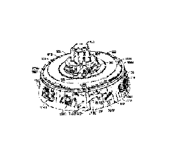
Une figure unique qui représente un dessin illustrant l'invention.
États administratifs

2024-08-01 : Dans le cadre de la transition vers les Brevets de nouvelle génération (BNG), la base de données sur les brevets canadiens (BDBC) contient désormais un Historique d'événement plus détaillé, qui reproduit le Journal des événements de notre nouvelle solution interne.

Veuillez noter que les événements débutant par « Inactive : » se réfèrent à des événements qui ne sont plus utilisés dans notre nouvelle solution interne.

Pour une meilleure compréhension de l'état de la demande ou brevet qui figure sur cette page, la rubrique Mise en garde , et les descriptions de Brevet , Historique d'événement , Taxes périodiques et Historique des paiements devraient être consultées.

Historique d'événement

Description Date
Rapport d'examen 2024-04-03
Inactive : Rapport - Aucun CQ 2024-03-29
Lettre envoyée 2022-12-28
Exigences pour une requête d'examen - jugée conforme 2022-10-24
Toutes les exigences pour l'examen - jugée conforme 2022-10-24
Requête d'examen reçue 2022-10-24
Représentant commun nommé 2021-11-13
Inactive : Page couverture publiée 2021-07-26
Demande publiée (accessible au public) 2021-06-06
Inactive : CIB en 1re position 2021-03-30
Inactive : CIB attribuée 2021-03-30
Lettre envoyée 2020-11-19
Exigences de dépôt - jugé conforme 2020-11-19
Demande de priorité reçue 2020-11-18
Exigences applicables à la revendication de priorité - jugée conforme 2020-11-18
Représentant commun nommé 2020-11-03
Inactive : Pré-classement 2020-11-03
Demande reçue - nationale ordinaire 2020-11-03
Inactive : CQ images - Numérisation 2020-11-03

Historique d'abandonnement

Il n'y a pas d'historique d'abandonnement

Taxes périodiques

Le dernier paiement a été reçu le 2023-09-05

Avis : Si le paiement en totalité n'a pas été reçu au plus tard à la date indiquée, une taxe supplémentaire peut être imposée, soit une des taxes suivantes :

  • taxe de rétablissement ;
  • taxe pour paiement en souffrance ; ou
  • taxe additionnelle pour le renversement d'une péremption réputée.

Les taxes sur les brevets sont ajustées au 1er janvier de chaque année. Les montants ci-dessus sont les montants actuels s'ils sont reçus au plus tard le 31 décembre de l'année en cours.
Veuillez vous référer à la page web des taxes sur les brevets de l'OPIC pour voir tous les montants actuels des taxes.

Historique des taxes

Type de taxes Anniversaire Échéance Date payée
Taxe pour le dépôt - générale 2020-11-03 2020-11-03
TM (demande, 2e anniv.) - générale 02 2022-11-03 2022-10-11
Requête d'examen - générale 2024-11-04 2022-10-24
TM (demande, 3e anniv.) - générale 03 2023-11-03 2023-09-05
Titulaires au dossier

Les titulaires actuels et antérieures au dossier sont affichés en ordre alphabétique.

Titulaires actuels au dossier
CESKA ZBROJOVKA A.S.
Titulaires antérieures au dossier
JAROSLAV MALINA
Les propriétaires antérieurs qui ne figurent pas dans la liste des « Propriétaires au dossier » apparaîtront dans d'autres documents au dossier.
Documents

Pour visionner les fichiers sélectionnés, entrer le code reCAPTCHA :


Pour visualiser une image, cliquer sur un lien dans la colonne description du document (Temporairement non-disponible). Pour télécharger l'image (les images), cliquer l'une ou plusieurs cases à cocher dans la première colonne et ensuite cliquer sur le bouton "Télécharger sélection en format PDF (archive Zip)" ou le bouton "Télécharger sélection (en un fichier PDF fusionné)".

Liste des documents de brevet publiés et non publiés sur la BDBC .

Si vous avez des difficultés à accéder au contenu, veuillez communiquer avec le Centre de services à la clientèle au 1-866-997-1936, ou envoyer un courriel au Centre de service à la clientèle de l'OPIC.

({010=Tous les documents, 020=Au moment du dépôt, 030=Au moment de la mise à la disponibilité du public, 040=À la délivrance, 050=Examen, 060=Correspondance reçue, 070=Divers, 080=Correspondance envoyée, 090=Paiement})


Description du
Document 
Date
(aaaa-mm-jj) 
Nombre de pages   Taille de l'image (Ko) 
Description 2020-11-04 6 210
Revendications 2020-11-04 1 38
Abrégé 2020-11-04 1 11
Dessins 2020-11-04 5 208
Dessin représentatif 2021-07-25 1 29
Demande de l'examinateur 2024-04-02 4 166
Courtoisie - Certificat de dépôt 2020-11-18 1 579
Courtoisie - Réception de la requête d'examen 2022-12-27 1 423
Nouvelle demande 2020-11-02 7 375
Requête d'examen 2022-10-23 4 153